CRC Carpet Knife Generation-XL User manual

New Gen-XL Features
** Micro size left pod plate
** “EZ set” molded center pivot
** 1-piece long XL clamping links
** New CRC Encore Bladder shock
** Extra room for center mounted speedo
** Features new small Kimbrough spur gear!
** New antenna/shock mount w/ locking set screw
** ABP - Adjustable battery position w/ molded position pieces
** Aerospace grade 100% pure carbon fiber chassis and structure parts
** Proven Pro-Strut front end with symmetrical components +optional roll centers
CRC Gen-XL
SWEEPS the 2009
IIC in Las Vegas!
Gen-XL wins all 3
1:12th classes!
CRC Encore Shock
Bladder shock
w/removable spring.
Super tough hardened
steel shock shaft.
Calandra Racing Concepts
6785 Martin Street ~ Rome, NY 13440 ~ Tel + Fax 315-338-086 ~ www.teamcrc.com
tires, servo and
servo saver
not included
Part #
3202
1:12th competition racer
designed for 1s 3.7v lipo
batteries + brushless motors
1:12th competition racer
designed for 1s 3.7v lipo
batteries + brushless motors
8100734 03202
™
Carpet Knife Generation XL
Assembly Manual
and Tuning Guide
Calandra Racing Concepts, Inc.
6785 Martin Street ~ Rome, NY U.S.A. 13440
Tel + Fax 315-338-0867
www.teamcrc.com ~ info@teamcrc.com

Center Pivot Base
2-56 Button Head
Alum Pivot ball
4-40 Thin Hex Nut
4-40 x ½” FH Steel Washer
Assemble the Molded Center Pivot assembly as shown. Tighten the 2-56
button head screws [4] enough to remove any up and down play, be sure the
flanged pivot ball [2] pivots freely.
*Note - Sometimes it is helpful to over-tighten the screws, then work
the ball around by hand, and then loosen the screws so the ball floats around
very free. Do not over-tighten the screws too much or you could warp the
pivot socket.
slightly
Red Locknut
1 - Place the 4-40 x ½” screws [5] through the graphite chassis [6] in
the holes shown. Tighten a 4-40 thin hex nut [7] down fairly tight.
2 - Then, after both thin hex nuts are tight on the 2 mounting screws,
drop the assembled center pivot over the screws. The assembly should
slide down over the hex nuts, not sit on top of them.
3 - Drop a washer [8] over each screw above the center pivot
assembly.
4 - Thread on the 4-40 red locknuts [9]. Do not tighten them yet as we
will adjust this in a later step.
Bag 1
Center Pivot
Bag 1
Center Pivot
1
12
3
4
4
789
5
7
9
8
6
5
1
2
4
Center Pivot Cap
3

Bag 2
4-40 x 5/16”
FH steel
4-40 x ½”
FH Steel
One-Piece
Side Links
Graphite
Bottom Plate
Red Low-
Profile Ball
1 - In Bag 2, find the graphite
bottom plate [10]. Secure it to the
pivot ball assembly with the ½” flat
head screw [5]. Secure it tight with
the red hex standoff [11].
2 - Find the 4 red low profile balls
[12]. Secure them as shown with
the steel 5/16” screws [13]. When
secure, pop the plastic side links
[14] on the balls so that the flat
side of the ball sockets face the
center of the car.
3 - Insert the 2-56 button head
screws into the side links from the
outsides of the chassis as shown,
and only tighten them enough so
that the links will not pop off the
balls. You want the links to pivot
very freely without any drag.
Be sure the 2 aluminum locknuts on top of the center pivot are slightly loose.
There should be a washer under each alum locknut. Notice that the center pivot
“floats" or moves slightly on the 2 screws. This "floating" allows the links
to "free up". This ensures that the rear bottom plate pivots freely on the links
and center pivot ball. This is a crucial step when setting up the Gen-XL.
Snap the 2 links on the balls as shown above. They should rock freely on
the pivot balls.
Place the chassis/backplate on a flat surface. No tires and
no diff on the car! A smooth table or desk should do. Be
sure that the rear bottom plate and chassis are in a
straight line, flat against the table, again, no tires on the
car. Lightly “tap” the chassis and rear pod releasing any
tension in the links. Keep the chassis flat on the table for step 4.
Holding the chassis at the hold point “H” by pressing
the chassis down to the table. Slowly tighten the 2 locknuts that
secure the center pivot. For now, just lightly
snug one side then the other.
Pick up the car and check the pivoting action of
rear lower plate. Rotate the rear plate from side-to-
side. It should move free without binding or "clicking".
If it does not, loosen the pivot locknuts and repeat steps 3+4.
If it rotates smoothly, tighten the locknuts on the center pivot more
securely. Do this by again holding the chassis down to the table at the
hold point “H”. Slowly and carefully fully tighten the locknuts that hold the center
pivot to the chassis. The handling of the Gen-XL hinges (pun intended!) on the
free movement of this rear plate. Be sure that the rear links and rear plate are free and not binding.
(not the rear pod)
H
H
1.
2.
3.
4.
5. 5
Rotate
Center Pivot
Setting the One-piece links
2
Red
Locknut
9
10
4
10
11
12
14
13
12
13
14
5
2-56 Button Head
4
5

Left Side Plate
Graphite X-brace
Graphite
Top Plate
1 - Install the black 2-56 ballstuds [15] into the graphite top plate [16]. These steel balls thread into the
graphite, no nut is needed. Be sure to start them straight and square and turn them in slowly so they do
not strip or break.
2 - Push the red ballstud [17] through the graphite plate [16]. Use a red locknut [9] to secure it. Attach the
assembled top plate to the Motor plate [19] using 3 1/4” button head screws [21].
3 - Install the Graphite X-brace [18] to the back of the Motor
Plate [19] and left side pod plate [20]. Use 4 1/4” button head
screws [21] to attach the graphite piece to the pod plates.
4 - Install the completed rear pod assembly to the rear bottom
plate using 4 1/4” flat head screws [22]. Keep an eye on these
screws during the first few runs of your car. They tend to
loosen until they take a “set” and then they WILL stay tight.
*Note - Although we are using steel screws in this kit, you may
opt to use optional aluminum screws in the future. We do NOT
recommend using thread lock in any aluminum to aluminum
application. The best way to keep these tight is by keeping a
close watch on their tightness after your first few runs.
In time, the screw will naturally “seat” and stay tight.
16
18 19
Bag 3
4-40 x 1/4”
Button Head 4-40 x 1/4”
Flat Head
Red Alum
4-40 Ballstud
2-56 Steel
Ballstud - Black
Rear X-Pod
3
15 17 21
Red Locknut
922
18
21
Motor Plate
20
15
9
16
17
20
19
21
22

Bag 4
4-40 x 3/8”
set screw
Thread the set screw
in until flush with the
bottom of the holder.
Molded Plastic
Spring Holder Graphite Tweak
Plate (x2)
INSERT TWEAK SCREWS IN BRACE ASSEMBLY
1 - Place the Tweak Brace [25] on a smooth, flat table and thread the
Tweak set screws [23] into the brace per the illustration. Try to be careful
to thread it in straight and perpendicular.
With the tweak screw threaded through the brace, thread spring holder
[24] onto the tweak screw as shown in the illustration. The tweak screw
should thread in until flush with the bottom of the spring holder. These new
spring holders do not require super glue to hold them to the tweak screws,
but a small dot can be added as a precaution if you wish.
Tweak Plates
4
23 25
25
23
23
24
White
Side Spring ½” Plastic Standoff
ATTACH SPRING TO HOLDER
Push the spring [26] into the groove on the plastic
holder [24]. Make sure that the first coil sits into the
angled groove. This allows the spring to sit flat on the
bottom plate. If the spring coil is not properly seated in
the groove, the spring will sit on an angle and make
the car difficult to tweak properly.
Bag 4
26
26 28
24
Red Alum
4-40 Ballstud
17
Red Locknut
9
4-40 x 3/8”
Button Head
27
Tweak Plates
Assemble the Tweak Plates
1 - Use the 3/8” button head screws [27] to fasten the plastic
standoffs [28] to the graphite tweak plate [26].
2 - Put the red ball stud [17] through the tweak plate and
secure with a red locknut [9] as shown in the illustration.
27
28
17
Make sure spring coil
is seated into groove
on spring holder.
26
9
24
1 - Mount the completed tweak brace assembly to the chassis
as shown using the 4-40 x 1/4” flat head screws [22]. Do this
for both left and right side tweak plates.
5
22
Bag 4
Tweak Plates 4-40 x 1/4”
Flat Head
22
Bag 5
2-56 set-
screw stud
2-56 Plastic
Ball Cup
Short 4-40 Plastic
Ball Cup (on tree)
.035”
Allen Driver
Delrin Plunger Aluminum Tube
.125 "
1
2
3
4
.188 "
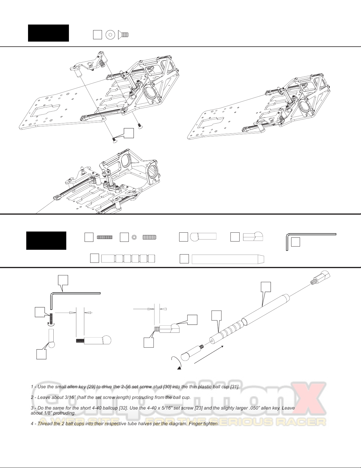
1 - Use the small allen key [29] to drive the 2-56 set screw stud [30] into the thin plastic ball cup [31].
2 - Leave about 3/16” (half the set screw length) protruding from the ball cup.
3 - Do the same for the short 4-40 ballcup [32]. Use the 4-40 x 5/16” set screw [23] and the slighty larger .050” allen key. Leave
about 1/8” protruding.
4 - Thread the 2 ball cups into their respective tube halves per the diagram. Finger tighten.
Damper Tubes 4-40 x 5/16”
set screw
76 29
30 31
29
30
31
76
32
32
34
33
34
33

** Adding the Damper Tubes to the Chassis assembly **
Snap the assembled & lubed damper tubes on the respective points as
shown in the diagram to the right. You will find it easier to snap on the
centered, smaller 2-56 ball studs first, then pop the outer, larger 4-40 ballcups
6
CRC
Tube
Lube
5
35
Completed Tube
5 - Add CRC Tube Lube [35] to each slot on the delrin plunger [33].
Build the tube and be sure it has smooth, damped action.
*** : fill only the slots, not the entire aluminum tube [34]. ***Note
Bag 5
Damper Tubes
Bag 6
Molded
ABP Braces
Adjustable Battery Position
36
4-40 x 1/4”
Flat Head
22
Your new Gen-XL continues to have CRC’s Adjustable Battery Positioning (ABP).
This adjustability gives the car a wide range of handling possibilities. We
recommend running the battery to the rear for the most steering entering the corner.
However, if the car is over aggressive on entry or tries to flip, moving the battery
forward will smooth it out.
Using the 4-40 x 1/4” flat head screws [22], push the screws through the chassis [6]
and then thread them into the plastic ABP braces [36] as shown in the diagram.
ABP - Rearward
36
22
ABP - Forward
36
22
ABP - Rearward
ABP - Forward

7
Bag 7
Center Shock
1 - Thread the spring adjuster nut [37] onto the shock body [38] as shown above. *This needs to be installed first or you will not be able to get it on later after the
lower end of the shock is assembled!*
2 - Insert only 1 of the small o-rings [39] into the lower end of the shock body [38]. Next, install the bottom shock plug [40] and tighten the bottom shock cap [41].
3 - Insert 1 of the small e-clips [42] into the lower groove of the shock shaft [43]. Slide the piston [44] over the shaft until it stops against the e-clip and then
secure it in place with the other e-clip in the end groove. Next, slide the other small o-ring [39] over the shock shaft and up against the piston. This o-ring acts as
a travel limiter.
4 - Put a small dab of the included shock oil on the threads of the shock shaft to lube it and then slide the shock shaft through the bottom end of the shock
carefully so you do not damage the o-ring with the threads on the shock shaft. Pull the shaft all the way through until the piston bottoms out in the shock body.
5 - Wipe off any excess oil from the threads of the shock shaft and then thread on the shorter of the 2 included ballcups [45]. *If you need to hold the shaft with
pliers, be sure to wrap a rag around the shaft first so the pliers do not damage the shaft. If there is any damage to the shaft, the sharp edges will damage theo-
ring and cause the shock to leak.
6 - Now with the shaft still fully extended, hold the shock body upright and fill with the included shock oil. Press the shaft in about half way and then return it to
full extension. Look inside the shock and you will notice small air bubbles in the oil. This is the rest of the air that was trapped below the piston. Allow enough
time for the air bubbles to work their way to the surface and pop.
7 - Once satisfied that all of the air is out of the shock, top off with oil and then insert the shock bladder [46] by laying one side into the oil and then rolling your
finger across the top of the bladder to expel any excess air and/or oil.
8 - Insert the flanged ballcup [47] into the upper shock cap [48] and then tighten this down over the shock bladder, being careful to not knock the bladder off its
seat and allowing air to enter the shock. *Double check that the shock is working smoothly through its range of motion and that you can fully compress the
shock. If it binds up before being fully compressed, then it has too much oil and you will need to crack the top cap loose and expel a very small amount of oil and
retighten.
9 - Slide the shock spring [49] over the shock body and keep in place by clicking the spring retainer [50] over the shock shaft and sliding it down over the short
ballcup to keep it in place.
37
45
50
43
39
41
40
49
38
39
42
44
46
47
48
(Lower groove)
(End groove)
51
Antenna /
Shock Mount
1 - Install the Antenna / Shock mount [51] using the 4-40 x 3/8”
flat head screws [52] so that the flat end points toward the front
of the car.
2 - Thread the red ballstud [17] into the rear hole of the shock
mount.
3 - Insert the white fiberglass antenna rod (not pictured) into the
front hole of the shock mount and lock it in place using the 1/8”
set screw [53].
51
17
52
Red Alum
4-40 Ballstud
17
4-40 x 3/8”
Flat Head
52
4-40 x 1/8”
Set Screw
53
CRC Encore Shock
(Round end)
(Flat end)
53

8
Install the shock on the ball studs as shown.
Squeeze the ballcups over the ball studs with pliers.
Do not push down on the shock in the center and try
to pop both ballcups on at once or damage to the
shock will occur.
Bag 7
Center Shock
2-56 x ½” SH
Delrin
Pivot Ball
CRC Pro-Strut
Front End
2-56 Red
Locknut 4-40 x 7/16” FH
1 - Pop the delrin pivot ball [54] into the lower arm [55]. Place the arm on a strong table and push the ball in
with the back of screwdriver handle. Or preferably, you can use CRC’s 4279 Ball popper pivot ball tool. Notice
the “lip” of the delrin pivot ball is pointing upward. The diagram to the left represents a right side lower arm. For
the left side, flip the second arm over and be sure the pivot ball is installed with the lip again facing up.
2 - Once the ball is popped in, insert the black 2-56 clamp screw [56] through the hole in the lower arm. Thread
the 2-56 red locknut [57] onto the black screw. Tighten the screw slowly, continuously checking the pivot ball.
When it begins to bind, back the 2-56 screw off a bit. The ball should be free to pivot with just a bit of drag.
There is no need to have this ball super loose, a slight drag will be just the right amount of clamping force.
Check this fit after a few runs as the ball will wear and require additional clamping force.
Lip
1 - Install the upper A-arm mount [58] with the amount of Dynamic Caster desired. The options are 0, 5 and 10
degrees. The part shown to the right is the 5 degree version and is a good starting point. The 10 will angle
down more toward the front of the car with the 0 being parallel to the chassis. The general thought is the more
Dynamic Caster, the more steering the car will have at corner entry.
2 - Locate the 3, 4, and 5 mm spacers [59]. Use the 5 mm thickness for stock CRC High Roller tires trued to
1.8”. For smaller tires, use the 4 and 3 mm versions. For finer ride height adjustments, use the CRC #4262
optional front shim set. This set contains .25, .5 and .75mm plastic ride height shims. After selecting the
proper spacer, push the 4-40 x 7/16” screw [60] through the plastic ride height spacer [59], then through the
lower arm [55], and then thread the screw into the upper A-arm mount [58]. Be sure NOT to over tighten.
54
54
55
56
56
57
57
58
59
60
55
60
Bag F
Hinge Pin
Upper Cap
White Teflon
Washer
2-56 Button Head
63
62
64
65
1 - Break the mold tree from the upper A-arm [61]. You can clean up the mold gates
with an X-acto or Dremel tool.
2 - Locate the upper arm hinge pin [62] and slide it into one half of the upper arm.
Locate 3 small white teflon washers [63]. Push the hinge pin through the 3 washers.
Then continue to push the hinge pin all the way into the upper arm.
61
62
63
58
64 65
3 - Now, install the arm/pin/washer assembly onto the upper arm mount [58]. Put the hinge pin in
the channel. At this point you can set your starting caster setting by moving these washers
forward and back. The position shown to the left will result in a competitive handling. Moving
them to the rear will increase steering from the center and exit of the corner.
If the fit of the upper arm is tight, these washers are made from teflon and will flatten slightly with
use.
4 - Install the upper cap [64] with 4 black 2-56 button head screws [65]. The upper cap is the
“clamp” for the hinge pin. Be sure to tighten so that any gap is gone, however, do not tighten
beyond that point as damage can occur to the upper a-arm mount holes.
9
Dual Axle King Pin
Steering Arm
Spring
Brass Set
Screw
E-Clip
2-56 SH
1 - Build up the left and right steering blocks [66] as shown to the left. Start by threading the 1/4” button head screw
[21] through the steering arm [67] and into the red low profile ball [12].
2 - Then, slide the steering arm assembly into the steering block, lining up the 2 mounting holes. Using the black 2-56
socket head screws [68], fasten the arm to the steering block. DO NOT OVER tighten. You will drive the screw
through the steering block, deforming the part.
1 - Push the Dual aluminum axle [69] into the plastic steering block [66]. Push it all the way
in firmly. Notice you can install the axle inline or trailing. Typically, this is installed trailing for
1/12th road racing. This will slightly slow the steering response as compared to inline.
2 - Take the King pin [70] on the end of the Allen key and slide it through the lower arm pivot
ball [54], & then thread it into the steering block. Thread it in until some resistance is met.
This is the King pin beginning to thread into the top of the steering block after traveling
entirely through the dual axle.
3 - Add the spring [71] to the king pin. The preload on the spring can be adjusted with the
king pin length. When on the king pin, you want the end of the spring flush with the e-clip
groove. Start by adjusting the king pin so you have to slip the e-clip [72] under the spring to
get it in the groove. Just a bit of preload.
4 - Once happy with the preload position, lock the king pin with the 4-40 brass set screw
[73] through the back of the steering block.
Red Low-
Profile Ball
12
69 70
67
71
73
72
68 Upper
Ball
74
Pro-Strut Front End
Bag F
4-40 x 1/4” BH
21
67
66
68
21
12
69
73
71
70
72
74 75
1 - Use the large 8-32 screws [77] to mount the front suspension assembly to the chassis.
Push the screw through the chassis and then screw into the lower front suspension arm.
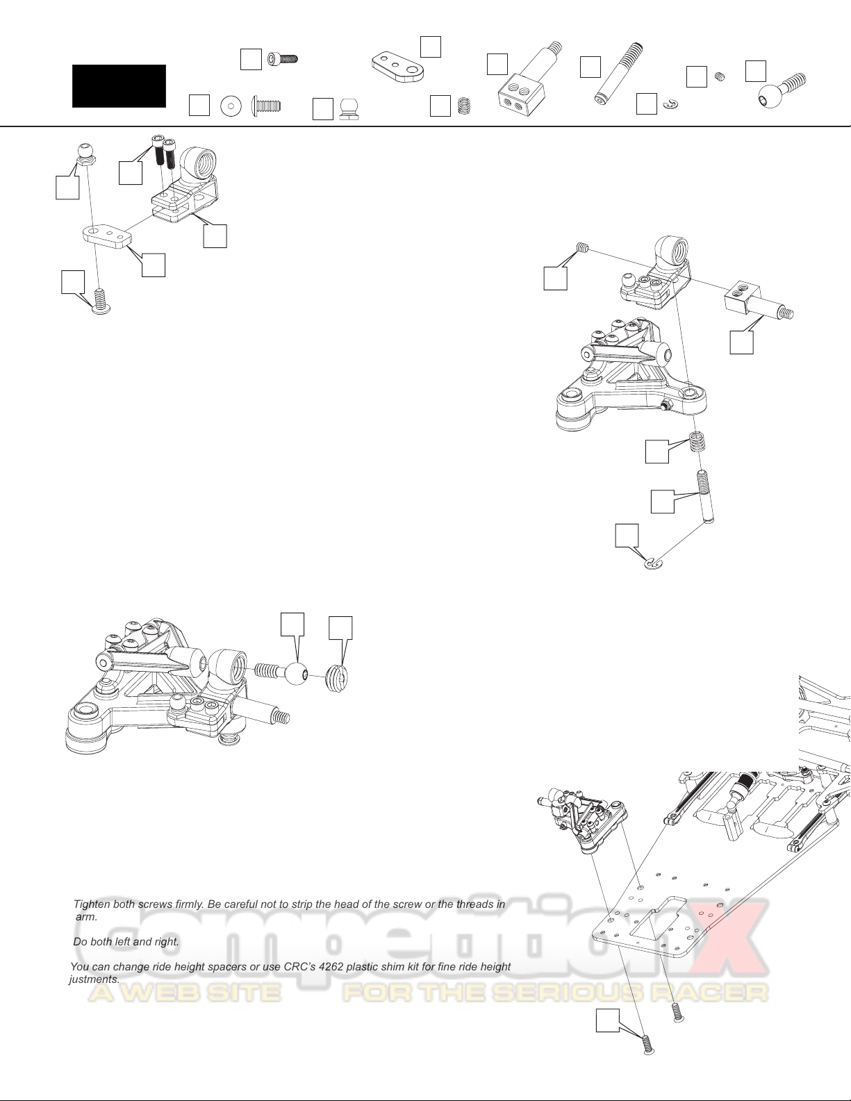
2 - Tighten both screws firmly. Be careful not to strip the head of the screw or the threads in
the arm.
3 - Do both left and right.
4- You can change ride height spacers or use CRC’s 4262 plastic shim kit for fine ride height
adjustments.
77
1 - Take the upper pivot ball [74] and push it though the steering block and
thread into the upper arm. Thread it in so there are no threads showing.
2 - Take the slotted capture insert [75] and thread it into the steering block. THIS
IS A BIT TRICKY .... as the insert must be fitted at a down angle as shown to the
left. DO NOT try to insert it horizontally into the steering block. It is actually
threaded in at a down angle toward the center of the car.
3 - Tighten this capture insert so that the steering movement is bound and slow.
Yes, we are actually slightly over tightening this piece FOR NOW. With the
steering movement bound from over tightening, move the steering to it’s limits,
back and forth. What we are doing is “breaking in” the upper ball/capture insert.
After a minute or so of break in, loosen the insert just enough so the steering is
free. Not too much or you will induce excessive free play.

Toward car
Small flange Large flange
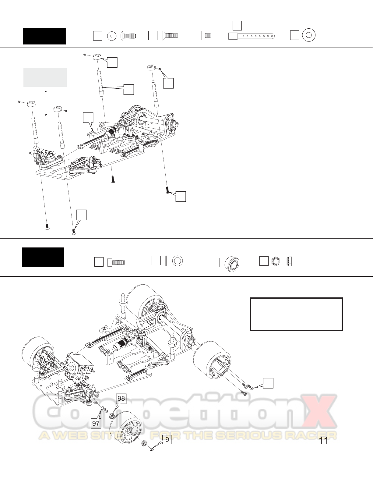
1 - Locate the tree of rear bearing carrier / ride height inserts [79]. Select the insert that will
work best with your tire size. (save the left over inserts as you will use these to increase the
rear ride height as the tires wear.) The #0 ride heights will work with full size CRC tires.
2 - Insert a 1/4” x 3/8” [80] Flanged Bearing into each of the ride height spacers.
3 - Now, with the bearings installed, insert the ride height spacers into the rear pod plates.
4 - Slide the rear axle [81] through two 1/4” shims [82] and into the 2 rear pod bearings.
5 - On the protruding axle, slip another 1/4” shim over the axle. Then slip the hub [83] on with
the small flange toward the bearing. The larger flange should face out.
6 - Lock the hub with the small cap screw [84] so that the axle has a very small amount of
side to side play in it. The thickness of 2 sheets of paper is plenty. You don’t want excessive
play here, you’re just making sure to not pinch the bearings.
1-INSTALL AND GREASE THE DIFF BALLS
Pop the 1/8” diff balls [85] into each of the outer ring of holes in the
diff gear [86]. The balls snap into the socket. Place a small dab of
silicone diff grease [87] on each ball. Use very little!
*(Holding the car on it’s side, with the rear axle pointing upright will
ease assembly of the diff.) Place 1 diff ring [88], and then a 1/4” x
3/8” plain bearing [89] over the end of the axle. Align the diff ring so
that it notches into the axle flange. Place the assembled gear with
the greased diff balls over the axle and push it down over the plain
bearing. Next, insert the other plain bearing into the back of the diff
hub [90]. Then, align the second diff ring with the notch on the back
of the diff hub. *(place a small dab of the diff grease on the hub first
to hold the ring in place.)* Now, slide the hub, bearing, & diff ring
down over the axle. Next, slide a flanged bearing [80] over the axle
and into the front of the diff hub.
2-DIFF ASSEMBLY
Light “D” ring
Bag 9
Small lip
toward bearing
Differential
10
1
** Balls in outer ring of holes in gear **
81
80
84
82
83
1/4” x 3/8”
Flanged Bearing
80
DIFF ASSEMBLY CONTINUED...
The diff spacer [91] has a small machined
lip on one side, point that lip toward the
bearing. Now, place the spring washer [92]
so that the cone points away from the gear.
The outside of the washer should be
against the diff spacer, and the inside of the
washer should be against the diff nut [93],
which now goes on last. *Be sure the 2 “D”
rings have settled into their notches. Just
snug the nut so the parts stay together on
the diff axle. Correct diff tension needs to
be set with tires on the car.
85
86
87
88
89
90
91
92
93
80
88
1/4” x 3/8”
Plain Bearing
89
Diff Hub
90
Lip
Diff Spacer
91
Spring Washer
92 Nylon Diff Nut
93
Bag 8
Differential Axle
Red Clamp Hub
1/4” Shim m2.5 x 6mm
Socket Cap
1/4” x 3/8”
Flanged Bearing
80 82 83 84
79 Ride Height Inserts
0
1
2
3
79
3 - Setting the Diff
Once the tires are on: Adjust the diff nut so that the tires spin back and forth freely when holding the spur
gear, but it is very difficult to slip the spur gear with your thumb when holding both tires. Again - DON’T
over-tighten so the outer diff hub bearing gets crushed! Re-check diff tension after the first run.
Body Post
Bag 10
Bag 11
BODY POSTS
Secure both front body posts [94] to the chassis with the 4-40 x 3/8” flat
head screws [52].
For the rear body posts, use the 4/40 x 3/8” button head screw [27].
Mount the body post to the Tweak Plate [25].
Thread the 1/8” set screw [53] into the plastic collar [95]. Adjust the collar
up and down the body post to accommodate the body shell used. Lock
the collar with the set screw.
Adjust body height
by raising or
lowering this collar
4-40 x 5/16”
Red Socket Cap 3/16” Shim 3/16” x 5/16”
Flanged Bearing
Body Posts
11
53
Body Post Collar
94
95
9194
95
27
25
52
96 97 98
Red Locknut
9
97
98
9
96
4-40 x 1/8”
Set Screw
53
4-40 x 3/8”
Flat Head
52
4-40 x 3/8”
Button Head
27
Tires are not included
with the Gen-XL, and are
shown for reference only.
JR
Expert
Hitec
(right side)
Air/Sanwa
Fut
KO
(left side) 99
Electronics
12
Red Servo Mount
99
4-40 x 1/4”
Flat Head
22
Steering Tie Rod Plastic Ball Cups
100
Servo Saver Brace
102
1.020”
NOT Included:
Kimbrough Servo Saver:
113 - Airtronics, JR, KO
114 - Futaba
131 - Hitec
101
100
Red Aluminum Servo Mounts
CRC has pre-drilled the Gen-XL for both JR, Expert and Hitec on one side,
and Futaba/KO/Sanwa on the other side. Refer to the diagram below for
instructions on what brand to use and in which locations.
Right side
JR - 3550, 3650, Expert 451, Hitec 225
Left side
Futaba 9650, KO 949, Air/Sanwa 94141,94145
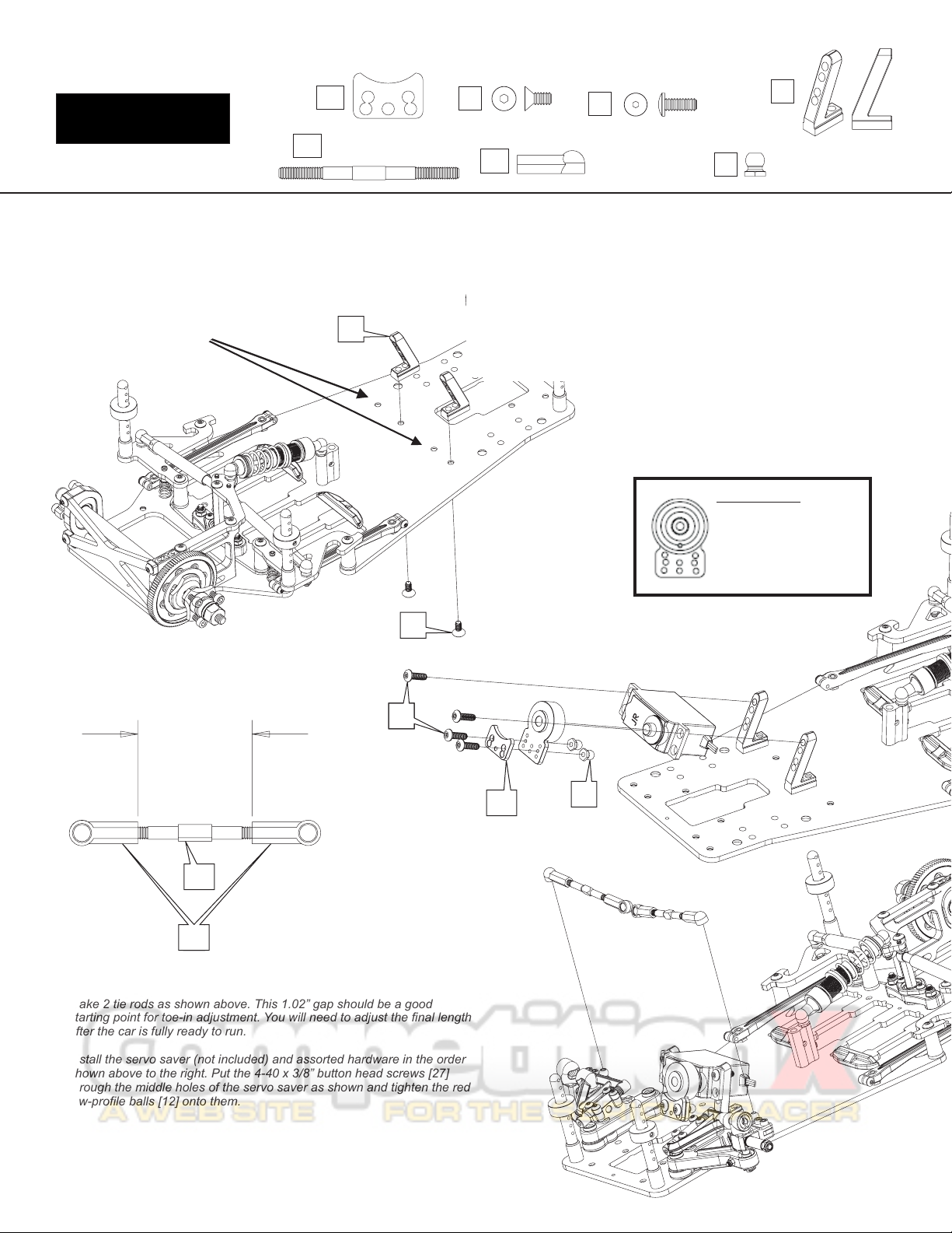
Tie-Rods
Make 2 tie rods as shown above. This 1.02” gap should be a good
starting point for toe-in adjustment. You will need to adjust the final length
after the car is fully ready to run.
Install the servo saver (not included) and assorted hardware in the order
shown above to the right. Put the 4-40 x 3/8” button head screws [27]
through the middle holes of the servo saver as shown and tighten the red
low-profile balls [12] onto them.
102
27
22
4-40 x 3/8”
Button Head
27
Red Low-
Profile Ball
12
12
101
1260
3351
13615
3362
3364


Other CRC Motorized Toy Car manuals


