Create ROC-2313 Quick start guide

1
ROC-2313 ReverseOsmosis Controller
1General
Theinstrumentisacombinedcontrolinstrumentofareverseosmosiscontrollerand anon-line
conductivityinstrument.Itcanperformtheoperation test,statuscontrolandon-linemonitoringofwater
qualityconductivity(combiningPLCcontrollerandconductivitymeter).Ittakesmultipleanti-interference
measures, adoptsuniqueprocess flowandgraphicalcontrolpanelwithLEDindicatorlampembedded,the
interface isfriendly;menu-drivenoperationisused,multiplegroupsofparameterscanbesetandmodified,
therequirements ofautomaticoperation aremet.
2Process Flow Selections
TherearetwotypicaloperationmodesforROsystem(asshowninFig.1AandB).Thisinstrument
canoperateinbothmodes inAand B.
3Functionsand Main TechnicalSpecifications
Lowfeed protection:
Incaseofrawwatersupplybreak-off,the LOWFEEDPRESS”lampwill belightened,the
nixietubewilldisplay ALA”andthebuzzerwillgiveanalarm,thecontrollerwillshutdownthe
wholeROsystem.Afterthat,thecontrollerwill keepdetectingthelowfeedswitch.Whenthewater
supplyis resumed, thesystemwill berestarted.
Lowpressureprotection:
Incaseoflowpressure,the LOWPRESS”lampwill belightened,thenixietubewilldisplay
ALA”and thebuzzerwill giveanalarm,thecontrollerwill shutdownthewholeROsystemandtry
tostartupforthefirsttimeafter1minute.Ifthewaterpressure isnormal,thewaterproducing
process will beresumed.If thestart-up failsforthree times, thesystemwillcomeintoadead-lock
status. Press theECS key(externalcontrolswitch)ortheresetkeytoexit and thenrestart.
High pressureprotection:
Incaseofhighpressureoverlimit,the HIGHPRESS”lampwill belightened,thenixietube
will display ALA”andthebuzzerwill giveanalarm,thecontrollerwill shutdownthewholeRO
Flushvale
Flushvalve
Level of raw
water
Raw
water
tank
Waste outlet
Low
press
pump
Pre-
processing 1
Pre-processing 2
Pre-processing 3
Direct drainvalve
Safety
filtering
Low press protection
Inlet valve
High
press
pump
Highpress protection
RO
membrane
Pure
water
tank
Fig. 1
-
AFirst level RO process flowwithrawwater tank
Fig. 1
-
BFirst level RO process flowwithdirect water supply
Safety
filtering
Low press
protection
Highpress protection
High
press
pump
RO
membrane
Flushvalve
Pure
water
tank
Inlet valve
Tapwater
Low
press
pump
Waste outlet
Low feed
protection
Pre-processing 1
Pre-processing 2
Pre-processing 3
Direct drainvalve
PDF 件使用 "FinePrint pdfFactory Pro" 试用版本创建 www.fineprint.com.cn

2
systemandwait fortheeliminationofhigh pressure.Whenthehighpressureeliminates, the
controllerwill trytostartupforthefirsttimeafter1 minute. Ifthewaterpressure isnormal, thewater
producingprocess will beresumed.If thestart-upfailsforthreetimes, thesystemwillcomeintoa
dead-lockstatus. Press theECS key(externalcontrolswitch)ortheresetkeytoexit and thenrestart.
Conductivityover limit alarm:
Whentheconductivityofthemeasuredsolution isoverlimit,the HIGH”lamponthepanel
will belightened,thebuzzerwill giveanalarm,andthecontrolrelaywill switchon(thisrelaycan
drivetoturnontheby-pass valve.Whentheconductivityfallsbelowthelimit,thealarmwill beset
off.
Maintechnicalspecifications:
1. Powervoltage:AC220V±15%50HzPowerconsumption: ≤3W
2. Environmentconditions:1)temperature:0~50℃;2)humidity: ≤85%RH
3. Measuring range:0~200μS/cm accuracy:1.5 level
4. Loadcapacityofoutputcontact: 3A/250VAC(themagneticvalveshouldbedriventhrough
intermediaterelay)
5. Operation pressureofconductance cell: 0~0.5Mpa
6.Mediumtemperature:5~50℃
7.Temperaturecompensation:automatictemperaturewith25℃as reference temperature
8. Distanceofmeasuringrange:lessthan30m(theex-factory configurationofelectrodecableis 5munless
thereis aspecialagreement)
9. Displaymode:3 1/2-digit LEDdigitaldisplay
10. Electrodeselected:1.0cm-1
11. outlinedimensions:96×96×110mm (height×width×depth)
meterboardhole:92×92mm (height×width)
4Front PanelIllustration
Fig. 2Front panel
PDF 件使用 "FinePrint pdfFactory Pro" 试用版本创建 www.fineprint.com.cn

3
Thedisplayboardis shownintheabovefigure, therearethree areas fromup todown:I, II and III.
Part I contains4LEDstatusindicatorlamps andconductivityvaluedisplayarea.The4LEDstatus
indicatorlamps respectivelyindicate:
POWER----indicatorlampforpowersupply
HIGH----indication forconductivityoverlimit alarm
μS/cm----conductivityvalue,representingthatthedisplayedvalueistheconductivityvalueofthe
producedwater
℃----temperaturevalueofthefluid,representingthatthedisplayedvalueisthetemperaturevalueof
thecurrentfluid
SLP(displayedinthenixietube)----ECS is notswitchedon and systemis inthestandbystatus.
FULL(displayedinthenixietube)----watertank is full and the FULL”lampwill belightened
ALA(displayedinthenixietube)---- ALARM”lampwill belightenedwhenalarmappears。
Part II istheindicationofROsystemoperationstatus,whichcontains9LEDindicatorlamps, andthe
lamps respectivelyindicate:
LOWFEEDPRESS----indicatorlampforlowfeedalarm,indicatingthatthereisnowaterintheraw
watertank orthewateris notsufficient.
LOWPRESS----indicationforinletwateroperation ofhighpressurepump, indicatingthattheinlet
wateroperation pressureofhigh pressurepumpis too low.
HIGH PRESS----indicationforoverpressureoperationofhighpressurepump, indicatingthatthe
outletpressureofhigh pressurepumpis too high.
INLETVALVE----indication forinletmagneticvalveturningon,indicatingthattheinletmagnetic
valveis turnedon.
M1----indicationforlowpressurepumpoperation,indicatingthatthelowpressurepumpisswitched
on.
M2---- indicationforhighpressure pumpoperation,indicatingthatthehighpressurepumpis
switchedon.
RO----indicationforwaterproducingstatus,indicatingthattheROsystemisinwaterproducing
operation.
FLUSHVALVE----indicationforflushmagneticvalveturningon,indicatingthattheflushmagnetic
valveis turnedon.
FULL----indicationforfull purewatertank,indicatingthatthewaterlevelinthepurewatertankhas
reachedthehigh limit.
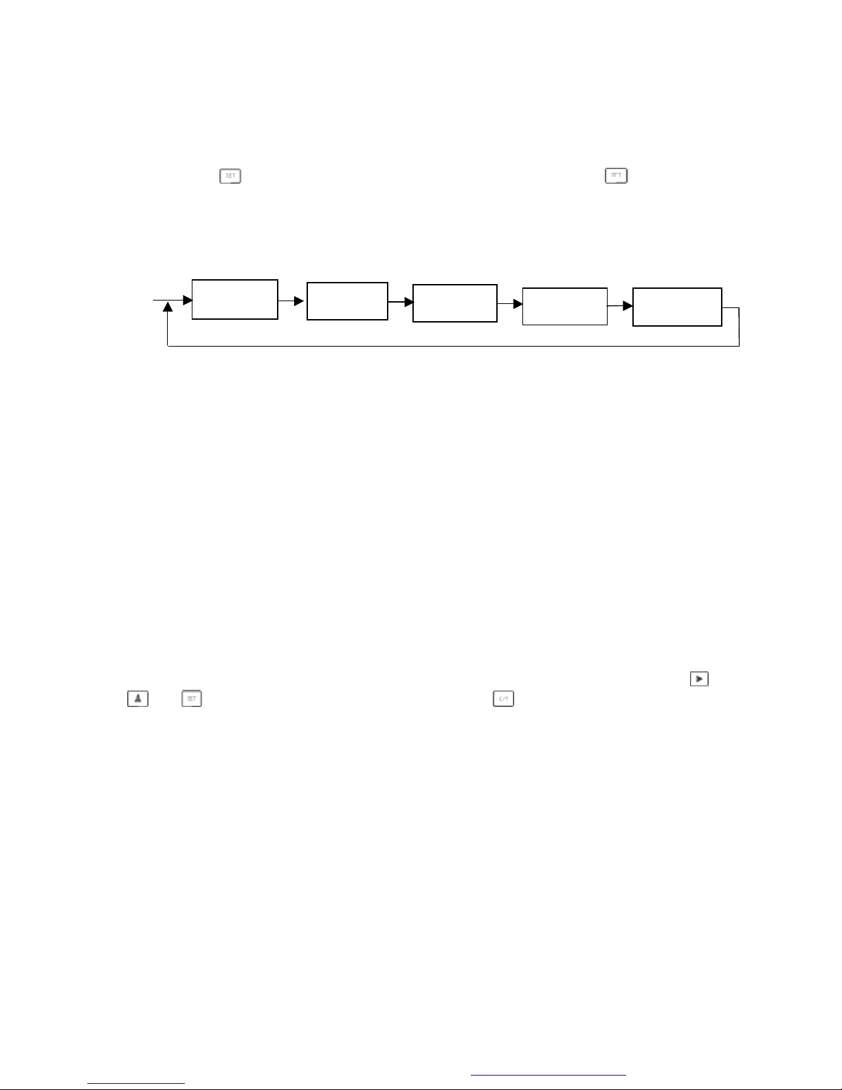
Part III contains setting and operation keys, theirmeanings are:
----parametersetting key, selecttheparameteritems tobemodifiedorinquired.
----circularlyselectthousand, hundred, tenand unit digit, theselecteddigit flashes.
----adjustthenumberoftheselecteddigit (circlefrom0 to9)
----C/Tkey,confirmtosavethemodifiedparameterinparametermodification orswitch between
theindication valueofconductivityand temperatureinmeasuring status.
PDF 件使用 "FinePrint pdfFactory Pro" 试用版本创建 www.fineprint.com.cn

4
5RearPanelIllustration
Since small relayisusedinthecontroller,whendrivinglargerinductiveload,intermediaterelayor
contactormustbeused, directdriving is notallowed.
Note:ZJ—intermediaterelayCJ---magneticcontactor(refertoappendix fortypeselection)
Therear connecting terminals areshowninthediagram, thedefinitions oftheterminals are:
Terminals fromupto downontheleft:
9----outputcontactterminalofhigh pressurepumpon/offcontrol(normallyopen, passive)
10---contactterminalofconductivityoverlimit control(normallyopen, passive)
11--- outputcontactterminaloflowpressurepumpon/offcontrol(normallyopen, passive)
12--- outputcontactterminalofinletmagneticvalveon/offcontrol(normallyopen, passive)
13--- outputcontactterminalofflushmagneticvalveon/offcontrol(normallyopen, passive)
14---a common terminalusedjointlybythecontrolsignals ofterminal9, 10, 11, 12 and 13.
15, 16---connection terminalof220Vcommercialpower.
Terminals fromupto downontheright:
1---inputterminalofhighwaterleveldetectionswitchofpurewatertank (normallyopen,closein
caseoflowwaterlevelofpurewatertank)
2---inputterminalofboosterpumpoverpressuredetectionswitch(normallyclose,switchoff incase
ofoverpressure)
3---inputterminalofinsufficientlowpressuredetectionswitch(normallyopen,closeatapreset
pressure)
4---inputterminalofrawwaterlowfeeddetection switch(normallyopen, closewhenwaterexists)
If yoursystemhasarawwatertankasshowninFig.1-A,thisterminalisconnectedtothe
normallyopencontactoftherawwatertanklowlevellimit,it willclosewhenwaterexists;ifyour
High pressure
pump
Condu
ctivity
overlimit
Lowpressure
pump
Inlet valve
Flushvalve
Common terminal
at powerside
Powercontrol
side Conductance
electrode Status
detection side
Common terminal
at detection side
Reset
External control
switch
Lowfeedof
rawwater
Lowpressureof high
pressure watersupply
Overpressureof high
pressure pump
High waterlevel of
pure watertank
Green Red White
Yellow
Fig. 3Rear panel connectiondiagram
PDF 件使用 "FinePrint pdfFactory Pro" 试用版本创建 www.fineprint.com.cn

5
systemadoptsdirectwatersupplyfromtapwateras showninFig. 1-B, thenthis terminalis connected
tothenormallyopencontactofthepressureswitchoflowfeedprotection,andit will closewhen
waterpressureis normal.
5---terminalofexternaloperationswitchofcontroller,ECS (thesystemoperateswhenit isswitched
on).TheECS switchmaybecontrolledbythekeyswitchinstalledonthecabinetpanel, ifakey
switchis notused, pleaseconnect terminal5 and8 inshort circuit.
6---Resetsignal,maybeconnectedtoaresetbuttonon thecabinetpanel,usedforresetofhighand
lowpressurealarms.
8--- acommon terminalusedjointlybythedetection signals ofterminal1,2,3,4,5 and 6.
Terminals fromleftto rightinthemiddle:
22---inputwireofconductance electrode(greenwire)
23---inputwireofconductance electrode(redwire)
25---inputwireofconductance electrode(whitewire)
26---inputwireofconductance electrode(yellowwire)
Restterminals including terminal7, 17,18,19,20,21,24 arenotinternallyconnected.
PDF 件使用 "FinePrint pdfFactory Pro" 试用版本创建 www.fineprint.com.cn

6
6Electricalcontrolcircuitdiagram4 2313(forreference)
High
pressure
pump
Low
pressure
pump
Highpressurepump
Lowpressurepump
Controlexecution
ControllerROC-2323
Signalcontrol
Inletmagneticvalve
Flushmagneticvalve
Detection
common
terminal
Reset
Externalcontrol
Lowfeedofrawwater
Lowpressure
Highpressure
Highwaterlevel
Powerinletwire
Masterswitch
Overlimitmagneticvalve
PDF 件使用 "FinePrint pdfFactory Pro" 试用版本创建 www.fineprint.com.cn

7
7Operation Method
Whentheinstrumentispoweredon,the POWER”lampwillbelightened,and thenixietubewill
displaytheconductivityvalue.Switchon ECStostartwaterproducing,standbyinthenixietubeifit isnot
switchedon.
APress key,thenixietubeindicates 1.000”(electrodeconstant).Press keyagainand
again, thefollowing menu items will comeout:
Electrodeconstant: thisvalueiskeyedinbythemanufactureratex-factory,it shouldnotbe
modifiedatwill.Incaseofreplacementofelectrode,pleaseenterit underthe
direction ofthemanufacturer.
Conductivitylimit value:thedefault valueis 100.0”(operation limit).
Flushtimeatstart-up: A-005”005”isthedefault value,theunit is second”,andthesetting
rangeis0~249s. If thesettingis 90”,thenthemembranewill be
flushedfor90s ineachtimethesystemstartup toproduce water.
Flushtimeatwaterlevel: B-005”005”isthedefault value,theunit is second”,andthe
settingrangeis 0~249s. Ifthesettingis 90”, thenineach timethat
thepurewatertankisfull andthesystemstops, orthesystem
restartafterlowwaterlevelisdetected,themembranewill be
flushedfor90s.
Flushinterval: C-03”03”is thedefault value, theunit is hour”, and thesettingrangeis 0~99h.
If thesettingis 03”,thenthemembranewillbeflushedonceat
every3 hours ofcontinuous waterproducing orstanding bystatus.
If youarenotsatisfiedwiththeabovementionedparametersettings, youcanmodifythemby ,
and keys. When thedatamodificationisfinished,press keytosavethedataandgobackto
measuringstatus(ifyoudon’tpress thiskey,thesystemwill automaticallygobacktomeasuringstatus
after3 minutes, butthedatamodification will notbesaved.)
1. 000
100. 0
C
03
B.005
A. 005
Settingof
electrode constant
Settingofconductivity
limit value
Settingofflush
timeat start
-
up
Settingofflush
timeat water level
Settingofflush
interval
PDF 件使用 "FinePrint pdfFactory Pro" 试用版本创建 www.fineprint.com.cn

8
8Connectionforautomaticreverse flushing
RelayJ1shouldbeaddedforreverseflushing.TwocontactingpointsJ1-1,J1-2isnormallyopenand
close.J1iscontrolledbypretreatmenttimerand timeofreverseflushingissubjecttoclosetimeof
normallyopencontacting point.
9Measurementelectrode(CELL)installation
Toensuretherealmeasurementresult,datadistortion causedbyairbubbleordeadwaterin
conductancecell shouldbeavoided.Theinstallationshouldbeperformedstrictlyaccordingtothe
following drawing:
Notes:(1)Theelectrodeshouldbeinstalledatalowerlocationinthepipewheretheflowspeedissteady
and airbubbles areseldomgenerated.
(2)Nomattertheconductancecell ishorizontallyorverticallyinstalled,it shouldbedeeply
insertedintothemoving water.
(3)Theconductivitysignalisweakelectronicsignaland itscollectingcableshouldbeseparately
installed.Theyshouldnotbeconnected tothesamegroup ofcablejointorterminalboardwith
thepowerline.
(4)Whenthemeasurementcableneeds tobelengthened, it’s recommendedtousethecableprovided
bytheoriginalmanufacturer,Whenalongerdistanceisinvolved,thelengthofthecable
(<30m)should beagreed onbeforedelivery, andifthelengthisover30m, atransmittershould
beused.
10 Maintenance
(1)Theconductance cell,asasophisticatedcomponent,cannotbedisassembled.Unless necessarythe
electrodecellshouldnotbetakenoutofmeasurementcell .Conductancecell shouldbecleaned
regularlyforkeepingsurface clean.whentheelectrodeplatinumblackcoatingisdirty,soakit in10%
dilutehydrochloricacidfortwominutes , thenrinseit withpurewatertokeepthesurface clean.
(2)Themeasurementcableisspecialcableandshouldnotbechangedatwill orit will causesignificant
error.
(4)Thespecialauxiliaryelectrodecell shouldbeusedincaseofdamage.
Pre-processing normally opencontact
Power
Externalcontrolswitch Controller
ECS
Low pressure contactor
PDF 件使用 "FinePrint pdfFactory Pro" 试用版本创建 www.fineprint.com.cn

9
11 Troubleshooting
1)Themagneticvalvecannotbeopened ---wrongselectionof magneticvalve,highvoltage
magneticvalveshouldbeused.
2)Lowpressure alarmwhenflush valveisopened---toomuchopeningextendforflush
valve,leakageofpressurecausedbywrongselection ortoolargehole.Selectingsuitable
magneticvalveoradjusting valveis usedbeforethemagneticvalve.
12 Complete sets ofinstrument
Panelmeter1Sensor1
Fixing clamp1Operation manual1
Appendix:Forusing thefollowing data, relativecontactorshouldbeselected
No.of
membrane
Pre-processing low
pressurepump Reverseosmosis high pressurepump
Water
Outflow
(m3/h)
WaterInflow
(m3/h) 4040
Model
8040
Mod
el
Low
pressure
pump(KW)
contactor
(A)
Lowpressure
membrane
1.05MPa
(KW)
contactor
(A)
Highpressure
membrane
1.55MPa(KW)
contactor
(A)
0.25 0.5 1
0.37 10 0.37 10 0.5 10
0.5 12
0.37~0.75
10 0.5~1.5 10 2.2 10
0.75 1.5 3
0.37~0.75
10 1.5 10 2.2 10
124
0.37~1.1
10 1.5 10 2.2 10
1.5 360.55~1.1
10 2.2 10 410
23.3 80.55~1.1
10 310 410
2.5 410 0.55~1.5
10 310 410
34.3 12 0.55~1.5
10 310 410
46.6 16 1.1~1.5
10 410 5.5 20
5820 1.1~2.2
10 5.5 20 7.5 20
610 61.1~2.2
10 5.5 20 7.5 20
813 82.2~410 11 40 11 40
10 17 10
2.2~5.5
10~20 11 40 15 40
15 21 15
4~7.5 10~20 11 40 15 40
20 28 20
4~11 20~40
PDF 件使用 "FinePrint pdfFactory Pro" 试用版本创建 www.fineprint.com.cn
Table of contents
Popular Controllers manuals by other brands

Audiovox Electronics
Audiovox Electronics MCS owner's manual

Spa-Quip
Spa-Quip SP601-15 user guide

ICM Controls
ICM Controls ICM326HN General Installation, Operation and Maintenance Instructions

Festo
Festo CPX-E-CEC-***-PN Series Instructions for use

Emerson
Emerson Fisher FIELDVUE L2t instruction manual

Unidrive
Unidrive ZoneLogix Plus Installation and troubleshooting guide