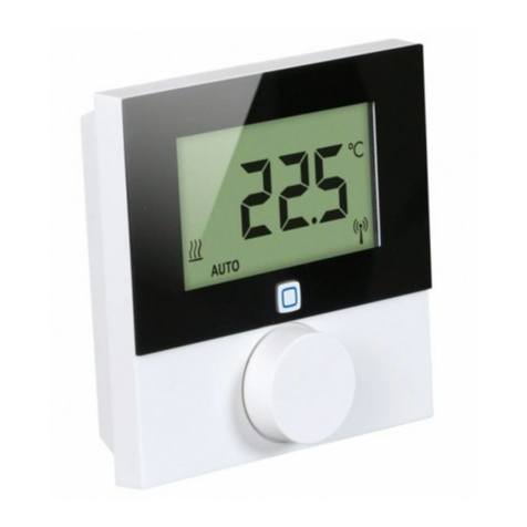
Alpha IP MIOB 21001 User manual

ENGNORSWE DANFINPOLRUS
132821.1628
MIOB 21001
Alpha IP

ENG NOR SWEDAN FIN POL RUS
2
ENG 3
2
DAN NOR 16
FIN 29
SWE 42
POL 55
RUS 68
1x 4x 4x
4,0 x 40 mm 6 mm

ENGNORSWE DANFINPOLRUS
3
ENG
DEUDEU
1 About these instructions 4
1.1 Validity, storage and forwarding of the instructions 4
1.2 Symbols 4
2 Safety 4
2.1 Intended use 4
2.2 Safety notes 4
3 Function 5
4 Device overview 5
4.1 Operating elements 5
4.2 Connections 6
4.3 Technical data 6
5 Installation 7
5.1 On-surface 7
5.2 DIN rail (optional) 7
6 Connection 8
6.1 Supply connection 8
6.2 Boiler connection (4.1/4.2) 8
6.3 Air dehumidifier connection (Access Point variant) 9
6.4 Change over pilot connection (Access Point variant) 9
6.5 Pump connection (5.1/5.2/5.3) 10
6.6 Humidity sensor connection (6.3/6.4) 10
6.7 External change over signal connection (6.1/6.2) 11
6.8 External timer connection (Access Point variant) 11
6.9 Temperature limiter connection (Access Point variant) 12
7 Commissioning 12
7.1 Teach-in without Alpha IP Access Point (stand-alone operation) 12
7.2 Teach-in to Alpha IP Access Point 13
8 Displays 14
9 Cleaning 14
10 Restoring factory settings 14
11 Decommissioning 14
12 Disposal 15
Contents

ENG NOR SWEDAN FIN POL RUS
4
ENG
1 About these instructions
1.1 Validity, storage and forwarding of the instructions
These instructions apply to the Alpha IP Multi-IO Box 21001 (MIOB). These instructions include infor-
mation necessary for the commissioning. These instructions must the read completely and thoroughly
before commencing any work with the device. These instructions must be kept and to be handed over
to future users.
These instructions as well as constantly up-to-date additional Alpha IP system information can
be found under www.alphaip.de.
System information, functions and operating steps from the Alpha IP Access Point (HAP 2001)
instructions must be followed.
1.2 Symbols
The following symbols are used in this manual:
Hazard symbols: Indicates a hazard
Note:Identifies important or useful information
ÖPreconditions
9Result from an action
• List without fixed order
1., 2. List with fixed order
2 Safety
2.1 Intended use
The Alpha IP Multi-IO Box (MIOB) station is a component of the Alpha IP Systems and serves
• for the functional extension of the Alpha IP indoor environment solution for radiant heating.
• for the connection of recirculation pump and boiler
• for the connection of temperature or humidity sensor
• for dew point monitoring
• for the control of operating modes
Every other use, modification and conversion is expressively forbidden. Improper use leads to dangers
the manufacturer cannot be held liable for and will exempt guarantees and liabilities.
2.2 Safety notes
All safety notes in these instructions must be observed in order to avoid accidents with personal dam-
age or property damage. No liability is assumed for personal damage and property damage caused by
improper use or non-observance of the danger notes. In such cases any warranty claim is invalid. There
is no liability for consequential damages.
Safety

ENGNORSWE DANFINPOLRUS
5
ENG
• Only an authorised electrician may open the device.
• Do not operate the device without device cover.
• Only use the product if it is in flawless state.
• This unit is not intended to be used by persons (including children) with restricted physical, sensory
or mental skills or who lack experience or knowledge. If necessary, these persons must be supervised
by a person responsible for their safety or receive instructions from this person on how to use this
unit.
• Ensure that children do not play with this device or its packaging. Children must be monitored if
necessary.
• In case of emergency, disconnect the complete room-by-room temperature control system.
• Observe the performance limits of the device and its environmental conditions.
• Lay the cables of connected consumers in a way that they do not lead to dangers (e. g. trip hazards)
for persons and pets.
• Only operate the device in a dry and dust-free environment.
• Do not expose the device to the influence of humidity, vibration, continuous solar radiation or other
types of radiation, coldness or mechanical load.
3 Function
The Alpha IP Multi-IO Box is the central control unit for the switching of recirculation pumps and boilers
in environments of residential use. The device allows the regulation of the room or water temperature
via the Alpha IP app or as standalone variant via room control unit.
Communication with other components is performed via the Homematic (HmIP) radio protocol. Radio
transmission is realised on a non-exclusive transmission path; thus, interference cannot be completely
excluded. Interference can be caused e. g. by switching processes, electric motors or defective electric
appliances.
Information about the functional extent of the device in conjunction with other components within the
Alpha IP system can be taken from the Alpha IP user manual.
4 Device overview
4.1 Operating elements
(A) System key (teach-in key and LED)
(B) Cover
A
B
Device overview

ENG NOR SWEDAN FIN POL RUS
6
ENG
Device overview
4.2 Connections
4.3 Technical data
Short designation of the device ALPHA-IP-MIOB
Supply voltage 230 V / 50 Hz
Power consumption max. 16 A
Max. switching power, output 1 3680 W, cosφ ≥0.95 (potential-free)
Max. switching power, output 2 1840 W, cosφ≥0,95 (potential-free)
Line type and line section solid and stranded cables
0.75 – 2.5 mm²
Protection type IP20
Protection class II
Ambient temperature 0 to 50°C
Dimensions (W x H x D) 198.6 x 155.8 x 33.5 mm
Weight 365 g
Radio frequency 868.3 MHz/869.525 MHz
Receiver category SRD category 2
Typical radio range 375 m
Duty cycle < 1 % per h/< 10 % per h
Guidelines 2014/53/EU Radio installations
2014/30/EU EMC
2011/65/EU RoHs
2014/35/EU Low-Voltage Directive
C
G
D
H
EF
I
(C)
Connection terminals for PE (earthing conductor)
(D) Connection terminals for N (neutral conductor)
(E) Connection terminal block 5 (changeable: 2 =
closing contact / 1 = opening contact.
e. g. for the connection of recirculating
pump, air dehumidifier, CO pilot)
(F) Connection terminals for IN1/IN2 (heating,
cooling or ECO operation, temperature
limiter or humidity sensor)
(G) Connection terminals for L (external conductor)
(H) Connection terminal 4 (e. g. for connection of
boiler, air dehumidifier, CO pilot)
(I) Connection terminal for AOUT (0-10 V output)
(J) LEDs for connection display: Pump (5.2), boiler
(4.2), status input 1 (IN1), status input 2 (IN2),
power supply (PWR) and change-over status
(C/O)
Connection terminal AOUT (I) is currently
without function.

ENGNORSWE DANFINPOLRUS
7
ENG
Installation
5 Installation
5.1 On-surface
5.2 DIN rail (optional)
Information about the installation of the Multi-IO Box on a DIN rail can be taken from the oper-
ating instructions of the optionally available DIN rail adapter.
21st
2nd
31st
2nd
4
Section 6: Connection
5
1st
2nd
93.5 mm
168 mm
1

ENG NOR SWEDAN FIN POL RUS
8
ENG
6 Connections
WARNING
Danger to life due to the electrical voltage at the Multi-IO Box!
• Only an authorised electrician may open the device.
• Always disconnect from the mains network and secure against unintended activation before open-
ing.
• Disconnect external voltages and secure against activation.
The wiring of the MIOB depends on several factors and must be planned and carried through carefully
by the installer.
The following cross-sections are applicable for plug-in/clamping connections:
• solid wire: 0.75 – 2.5 mm²
• stranded wire (with and without end sleeves): 0.75 – 2.5 mm²
• 8 - 9 mm insulation stripped off the wire
6.1 Supply connection
6.2 Boiler connection (4.1/4.2)
The terminal 4.1/4.2 is a relay as potential-free switch. For the standalone variant, only the boiler is
connected. If the Alpha IP Access Point is operated using the Alpha IP app, the terminal can also be
used for air dehumidifiers or for the Change Over Pilot (CO Pilot). Alternatively, with Homematic CCU 2
it is possible to use the terminal as a switch actuator.
PE
1.1
PE
1.2
L
2.1
L
2.2
N
3.1
N
3.2
1▼
4.1
1▼
5.3
▼
6.1
IN1
IN2
AOUT
4.2
IN1
IN2
C/O
▼
6.3
▼
6.5
GND
6.2
GND
6.4
GND
6.6
L▲
4.2
2▼
5.1
L▲
5.2
NN
LL
PE
1.1
PE
1.2
L
2.1
L
2.2
N
3.1
N
3.2
1▼
4.1
1▼
5.3
L▲
4.2
2▼
5.1
L▲
5.2
N
L
Connections

ENGNORSWE DANFINPOLRUS
9
ENG
6.3 Air dehumidifier connection (Access Point variant)
The Access Point variant allows the operation of a dehumidifier. The dehumidifier can be connected to
terminal 4.1/4.2 (see figure) as well as to the terminal 5.2/5.3. Excessive humidity values in the room air
can be lowered with the air dehumidifier.
6.4 Change over pilot connection (Access Point variant)
The Access Point variant allows to connect an internal pilot function for toggling the overall system
between the operating modes Heating and Cooling.
The CO pilot output signal can be connected to the terminal 4.1/4.2 as well as to the terminal 5.2/5.3
(fig.).
PE
1.1
PE
1.2
L
2.1
L
2.2
N
3.1
N
3.2
1▼
4.1
1▼
5.3
L▲
4.2
2▼
5.1
L▲
5.2
N
L
PE
1.1
PE
1.2
L
2.1
L
2.2
N
3.1
N
3.2
1▼
4.1
1▼
5.3
L▲
4.2
2▼
5.1
L▲
5.2
N
L
N
L
Heating
Cooling
Connections

ENG NOR SWEDAN FIN POL RUS
10
ENG
Connections
6.5 Pump connection (5.1/5.2/5.3)
Terminal 5.1/5.2/5.3 is a switching relay as potential-free change-over switch. For the standalone var-
iant, only the pump is connected. If the Alpha IP Access Point is operated using the Alpha IP app, the
terminal can also be used for air humidity sensors or for the CO pilot.
6.6 Humidity sensor connection (6.3/6.4)
Terminal 6.3/6.4 (IN2) is an input for potential-free contacts. For the standalone variant, only the hu-
midity sensor is connected. If the Alpha IP Access Point is operated using the Alpha IP app, the terminal
can also be used for temperature limiters (TL) or as external clock (ECO). A Homematic CCU 2 allows to
control all inputs and outputs individually.
Humidity sensors (to be provided by the customer) serve for dewing protection in the cooling mode.
PE
1.1
PE
1.2
L
2.1
L
2.2
N
3.1
N
3.2
1▼
4.1
1▼
5.3
L▲
4.2
2▼
5.1
L▲
5.2
N
L
▼
6.1
IN1
IN2
AOUT
4.2
IN1
IN2
C/O
▼
6.3
▼
6.5
GND
6.2
GND
6.4
GND
6.6
H
Humidity
sensor

ENGNORSWE DANFINPOLRUS
11
ENG
Connections
6.7 External change over signal connection (6.1/6.2)
Terminal 6.1/6.2 (IN1) is an input for potential-free contacts. For the standalone variant, only the
change-over signal (CO) is connected. If the Alpha IP Access Point is operated using the Alpha IP app,
the terminal can also be used for temperature limiters (TL) or as external clock (ECO).
6.8 External timer connection (Access Point variant)
The Access Point variant allows the operation of an external clockThe external clock can be connected
to terminal 6.1/6.2 (IN1, see figure) as well as to the terminal 6.3/6.4 (IN2). When the input is activated
by the timer, the heating zones parametrised for this are switched to night operation.
▼
6.1
IN1
IN2
AOUT
4.2
IN1
IN2
C/O
▼
6.3
▼
6.5
GND
6.2
GND
6.4
GND
6.6
N
L
Cooling
Heating
N
L
PE
1.1
PE
1.2
L
2.1
L
2.2
N
3.1
N
3.2
1▼
4.1
1▼
5.3 ▼
6.1
IN1
IN2
AOUT
4.2
IN1
IN2
C/O
▼
6.3
▼
6.5
GND
6.2
GND
6.4
GND
6.6
L▲
4.2
2▼
5.1
L▲
5.2

ENG NOR SWEDAN FIN POL RUS
12
ENG
Commissioning
6.9 Temperature limiter connection (Access Point variant)
The Access Point variant allows the operation of a temperature limiter (1). The temperature limiter can
be connected to terminal 6.1/6.2 (IN1, see figure) as well as to the terminal 6.3/6.4 (IN2). The temper-
ature limiter switches off the pump if too high flow temperatures for the floor heating are detected. If
the TL input is switched, the base station shuts down all actuators automatically.
7 Commissioning
Please read this section completely and carefully prior to commissioning.
The Multi-IO Box is taught in for standalone operation directly to the Alpha IP base station (FAL
21001/41001) or optionally to the Alpha IP Access Point (HAP 21001). For the variant with Alpha IP
base station, the subsequent configuration is done with the Alpha IP wall thermostat (WTH or WTHP
61001); for the Alpha IP Access Point variant, configuration is done with the Alpha IP app.
The device is preconfigured for the standalone solution.
7.1 Teach-in without Alpha IP Access Point (stand-alone operation)
Keep a minimum distance of 50 cm between the devices for teaching-in.
The teach-in process can be interrupted shortly pressing the teach-in key again. This will be
confirmed by a red illumination of the LED of the Multi-IO Box.
For the integration into an existing system, first the Alpha IP base station and subsequently the
Alpha IP Multi-IO Box must be brought into teach-in mode.
PE
1.1
PE
1.2
L
2.1
L
2.2
N
3.1
N
3.2
1▼
4.1
1▼
5.3 ▼
6.1
IN1
IN2
AOUT
4.2
IN1
IN2
C/O ▼
6.3
▼
6.5
GND
6.2
GND
6.4
GND
6.6
L▲
4.2
2▼
5.1
L▲
5.2
1
N
L

ENGNORSWE DANFINPOLRUS
13
ENG
For a standalone operation, the teach-in of the Alpha IP Multi-IO Box station must be performed via the
Alpha IP base station (FAL 21001/41001). Teach-in the device as follows:
1. Press the System key at the Alpha IP base station repeatedly, until the LEDs of all heating zones light
up in green.
2. Press the System key (A) of the Alpha IP base station for 4 seconds, until the LED of the System key
flashes rapidly in orange.
9The teach-in mode is active for three minutes.
3. Press the System key (A) of the Multi-IO Box for 4 seconds, until the LED of the System key flashes
in orange.
The System key LED will light up in green after a successful teach-in process. The process must
be repeated if the LED lights up in red.
7.2 Teach-in to Alpha IP Access Point
The Alpha IP Multi-IO Box can be taught in to the Alpha IP Access Point as well as to the
Homematic Central CCU2.
For a control via the Alpha IP app, the teach-in of the Alpha IP Multi-IO Box must be performed via the
Access Point (HAP 21001). Teach-in the device as follows:
ÖThe Alpha IP Access Point has been set-up via the Alpha IP app (see manual HAP 21001).
1. Open the Alpha IP app on your smart phone.
2. Select the menu item Teach-in device.
3. Press the System key (A) shortly until the LED flashes slowly in orange. The teach-in mode is active
for three minutes.
9The device will be displayed automatically in the Alpha IP app.
4. For confirmation, enter the last four digits of the device number (SGTIN) or scan the supplied QR
code. The device number can be found below the supplied QR code or directly on the device.
The System key LED will light up in green after a successful teach-in process. The process must
be repeated if the LED lights up in red.
5. Follow the directions of the app.
Commissioning

ENG NOR SWEDAN FIN POL RUS
14
ENG
8 Displays
Display Meaning Solution
Short flashing,
orange Radio transmission/
transmission attempt/
data transmission
Wait until the transmission has ended.
1 long lighting,
green Process confirmed You can continue your operations.
1 long lighting, red Process failed Retry.
Short flashing, or-
ange (once every 10
seconds)
Teach-in mode active Enter the last four digits of the serial number of
the
device for confirmation.
1 long lighting, red Process failed or duty
cycle limit reached Retry.
6x long flashing, red Device defective Observe the information in your app or contact
your specialist dealer.
1 lighting in orange
and 1 lighting in
green
Test indication You can proceed after the test indication has gone
out.
9 Cleaning
Only use a dry and solvent-free, soft cloth for cleaning.
10 Resetting factory settings
All settings will be lost when the factory settings are restored.
1. Keep the System key (A) pressed for 4 seconds, until it flashes rapidly in orange.
2. Release the System key.
3. Press the System key again for 4 seconds until it lights up in green.
4. Release the System key again.
9The factory settings are reset.
9The device restarts.
11 Decommissioning
WARNING
Danger to life due to the electrical voltage at the Multi-IO Box!
• Only an authorised electrician may open the device.
• Always disconnect from the mains network and secure against unintended activation before open-
ing.
• Disconnect external voltages and secure against activation.
1. Loosen all connected cables.
2. Uninstall the device and dispose of properly.
Decommissioning

ENGNORSWE DANFINPOLRUS
15
ENG
Disposal
12 Disposal
Do not dispose of the device with domestic waste! Electronic devices/products must be disposed
of according to the Directive for Waste Electrical and Electronic Equipment at the local collection
points for waste electronic equipment.
This manual is protected by copyright. All rights reserved. It may not be copied, reproduced, abbre-
viated or transmitted, neither in whole nor in parts, in any form, neither mechanically nor
electronically, without the previous consent of the manufacturer. © 2016
132821.1628

ENG NOR SWEDAN FIN POL RUS
16
DAN NOR
DA
1 Om denne vejledning 17
1.1 Gyldighed, opbevaring og videregivelse af vejledningen 17
1.2 Symboler 17
2 Sikkerhed 17
2.1 Bestemmelsesmæssig brug 17
2.2 Sikkerhedshenvisninger 17
3 Funktion 18
4 Oversigt over enheden 18
4.1 Betjeningselementer 18
4.2 Tilslutninger 19
4,3 Tekniske data 19
5 Montering 20
5.1 Frembygning 20
5.2 DIN-skinne (som option) 20
6 Tilslutning 21
6.1 Tilslutning forsyning 21
6.2 Tilslutning kedel (4.1/4.2) 21
6.3 Tilslutning luftaffugter (Access Point-variant) 22
6.4 Tilslutning Change Over Pilot (Access Point-variant) 22
6.5 Tilslutning pumpe (5.1/5.2/5.3) 23
6.6 Tilslutning fugtføler (6.3/6.4) 23
6.7 Tilslutning eksternt Change Over-signal (6.1/6.2) 24
6.8 Tilslutning eksternt tænd-sluk-ur (Access Point-variant) 24
6.9 Tilslutning temperaturbegrænser (Access Point-variant) 25
7 Ibrugtagning 25
7.1 Instruktion uden Alpha IP Access Point (standalone-drift) 25
7.2 Instruktion på Alpha IP Access Point 26
8 Visninger 27
9 Rengøring 27
10 Genetablering af fabriksindstillinger 27
11 Ud-af-brugtagning 27
12 Bortskaffelse 28
Indhold

ENGNORSWE DANFINPOLRUS
17
DANNOR
1 Om denne vejledning
1.1 Gyldighed, opbevaring og videregivelse af vejledningen
Denne vejledning gælder for Alpha IP Multi-IO boks 21001 (MIOB). Vejledningen indeholder infor-
mationer, som er nødvendige til ibrugtagning. Inden der arbejdes med enheden, skal nærværende
vejledning læses fuldstændigt og grundigt. Vejledningen skal opbevares og videregives til efterfølgende
brugere.
Denne vejledning og yderligere Alpha IP systeminformationer findes altid på www.alphaip.de.
Systeminformation, funktion og betjeningstrin fra vejledningen til Alpha IP Access Point (HAP
2001) skal tilgodeses.
1.2 Symboler
Følgende symboler bruges i denne vejledning:
Faretegn: Gør opmærksom på en fare
Henvisning: Kendetegner en vigtig eller nyttig information
ÖForudsætning
9Resultatet, som fremkommer af en handling
• Optælling uden fast rækkefølge
1., 2. Anvisning med fast rækkefølge
2 Sikkerhed
2.1 Bestemmelsesmæssig brug
Alpha IP Multi-IO boksen (MIOB) er del af Alpha IP systemet og tjener
• som funktionel udvidelse af Alpha IP klimaløsningen til temperering af arealer
• til tilslutning af cirkulationspumpe og fyrkedel
• til tilslutning af temperatur- eller fugtføler
• til dugpunktovervågning
• styring af driftstilstandene
Enhver anden brug, ændringer og ombygninger er udtrykkeligt forbudte. En ikke bestemmelsesmæssig
brug medfører farer, som producenten ikke hæfter for, samt til garantiudelukkelse og ansvarsfrihed.
2.2 Sikkerhedshenvisninger
For at undgå ulykker med personskade og materiel skade skal alle sikkerhedsinformationer i nærværen-
de vejledning overholdes. Der hæftes ikke for personskade og materiel skade, som forårsages af ukor-
rekt brug eller manglende overholdelse af farehenvisningerne. I sådanne tilfælde bortfalder garantien.
Der hæftes ikke for følgeskader.
Sikkerhed

ENG NOR SWEDAN FIN POL RUS
18
DAN NOR
• Enheden må kun åbnes af en autoriseret fagmand.
• Enheden må ikke bruges uden afskærmningen.
• Produktet må kun bruges i teknisk upåklagelig tilstand.
• Dette produkt må ikke blive betjent af personer (herunder børn) med begrænsede fysiske, sensoriske
eller mentale evner, manglende erfaring eller manglende viden, og de må ikke arbejde med det. I
givet fald skal disse personer være under opsyn af en person, som er ansvarlig for deres sikkerhed,
eller af denne instrueres i, hvordan produktet skal benyttes.
• Kontroller, at børn ikke leger med produktet eller emballagen. I givet fald skal børn være under
opsyn.
• I nødsituationer gøres hele enkeltrumsreguleringen spændingsfri.
• Overhold enhedens effektgrænser og omgivelsesbetingelser.
• Kablet fra tilsluttede forbrugere skal lægges således, at de ikke kan medføre farer for mennesker og
husdyr (f.eks. snublesteder).
• Brug kun enheden i tørre samt støvfrie omgivelser.
• Enheden må ikke udsættes for påvirkninger fra fugtighed, vibrationer, konstant sol- eller anden
varmeindstråling, kulde eller mekaniske belastninger.
3 Funktion
Alpha IP Multi-IO boksen er den centrale styreenhed til at tænde og slukke cirkulationspumper og fyr-
kedler i boliglignende omgivelser. Enheden gør det muligt at regulere rum- eller vandtemperaturen pr.
Alpha IP app eller som standalone-variant med rumtermostat.
Kommunikationen med andre komponenter sker via den trådløse Homematic (HmIP) protokol. Den
trådløse overførsel realiseres på en ikke eksklusiv transmissionsvej, hvorfor forstyrrelser ikke kan ude-
lukkes. Forstyrrende påvirkninger kan f.eks. fremkaldes af koblingsprocesser, elmotorer eller defekte
elektriske enheder.
Hvilket funktionsomfang for der kan fremkomme inden for Alpha IP systemet i samspil med andre
komponenter, kan ses i Alpha IP brugermanualen.
4 Oversigt over enheden
4.1 Betjeningselementer
(A) Systemtast (instruktionstast og LED)
(B) Afdækning
A
B
Oversigt over enheden

ENGNORSWE DANFINPOLRUS
19
DANNOR
Oversigt over enheden
4.2 Tilslutninger
4.3 Tekniske data
Kort betegnelse af enheden ALPHA-IP-MIOB
Forsyningsspænding 230 V/50 Hz
Strømforbrug 16 A maks.
Maks. Koblingseffekt udgang 1 3680 W, cosφ ≥0,95 (potentialfri)
Maks. Koblingseffekt udgang 2 1840 W, cosφ ≥0,95 (potentialfri)
Ledningsart og -tværsnit stiv og bøjelig ledning
0,75 – 2,5 mm²
Kapslingsklasse IP20
Beskyttelsesklasse II
Omgivelsestemperatur 0 til 50°C
Mål (B x H x D) 198,6 x 155,8 x 33,5 mm
Vægt 365 g
Radiofrekvens 868,3 MHz/869,525 MHz
Modtagerkategori SRD category 2
Typ. Trådløs rækkevidde 375 m
Duty cycle < 1 % pr. h/< 10 % pr. h
Direktiver 2014/53/EU Radioudstyr
2014/30/EU EMC
2011/65/EU RoHS
2014/35/EU Lavspændingsdirektiv
C
G
D
H
EF
I
(C) Tilslutningsklemmer for PE
(beskyttelsesleder)
(D) Afrembygning N (neutralleder)
(E) Tilslutningsklemblok 5
(omskifter: 2 = slutter / 1 = bryder.
f.eks. til tilslutning af en cirkulationspum
pe, luftaffugter, CO Pilot)
(F) Tilslutningsklemmer for IN1/IN2 (varme-,
køle- eller Ecodrift, temperaturbe
grænser eller fugtføler)
(G) Tilslutningsklemmer for L (leder)
(H) Tilslutningsklemme 4 (f.eks. for tilslutning
fyrkedel, luftaffugter, CO Pilot)
(I) Tilslutningsklemmer for AOUT (0-10 V ud
gang)
(J) LED-lys og tilslutningsindikator: Pumpe
(5.2), kedel (4.2), status input 1 (IN1),
status input 2 (IN2), forsyning (PWR) og
Change Over-tilstand (C/O)
Tilslutningsklemme AOUT (I) er aktuelt uden
funktion.

ENG NOR SWEDAN FIN POL RUS
20
DAN NOR
Montering
5 Montering
5.1 Frembygning
5.2 DIN-skinne (som option)
Omlysningerne om montering af Multi-IO boksen på en DIN-skinne kan ses i betjeningsvedled-
ningen til den DIN-skinneadapter, som kan leveres som option.
21.
2.
31.
2.
4
Kapitel 6: Tilslutning
5
1.
2.
93.5 mm
168 mm
1
Other manuals for MIOB 21001
1
Table of contents
Languages:
Other Alpha IP Controllers manuals