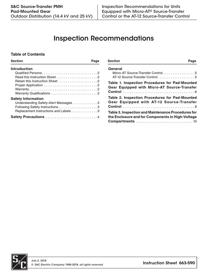
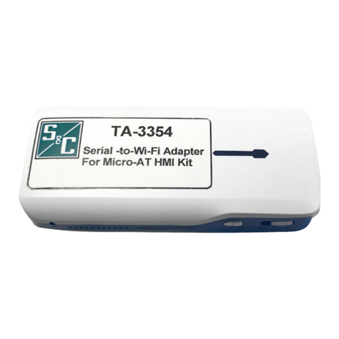
S&C PMH Operation and maintenance manual

S&C ELECTRIC COMPANY
INSTRUCTION SHEET
663-503
Page 1 of 35
August 14, 1995
Supersedes Instruction Sheet 663-503 dated 9-20-93 c
1995
s
S&C Source-Transfer PMH Pad-Mounted Gear
With Micro-AT
®
Control
Outdoor Distribution (14.4 kv and 25 kv)
Section Page Number
INTRODUCTION
Qualified Persons . . . . . . . . . . . . . . . . . . . . . . . . . . . . . . . . . . . . . 2
General. . . . . . . . . . . . . . . . . . . . . . . . . . . . . . . . . . . . . . . . . . . . . . 2
SAFETY INFORMATION
Understanding Safety-Alert Messages . . . . . . . . . . . . . . . . . . . . 3
Following Safety Instructions . . . . . . . . . . . . . . . . . . . . . . . . . . . 3
Replacement Instructions and Labels . . . . . . . . . . . . . . . . . . . . 3
SAFETY PRECAUTIONS . . . . . . . . . . . . . . . . . . . . . . . . . . . . . . . . . 4
OPERATING DESCRIPTION. . . . . . . . . . . . . . . . . . . . . . . . . . . . . . 5
COMPONENTS . . . . . . . . . . . . . . . . . . . . . . . . . . . . . . . . . . . . . . . . . 6
MINI-RUPTER SWITCHES
Decoupling . . . . . . . . . . . . . . . . . . . . . . . . . . . . . . . . . . . . . . . . . . 10
Coupling . . . . . . . . . . . . . . . . . . . . . . . . . . . . . . . . . . . . . . . . . . . . 10
Automatic Switch Operation . . . . . . . . . . . . . . . . . . . . . . . . . . . 11
Nonautomatic Switch Operation . . . . . . . . . . . . . . . . . . . . . . . . 11
Charging Operator (Nonelectrical) . . . . . . . . . . . . . . . . . . . . . . 11
Front Barriers . . . . . . . . . . . . . . . . . . . . . . . . . . . . . . . . . . . . . . . 12
FUSING
Assembling the Fuse . . . . . . . . . . . . . . . . . . . . . . . . . . . . . . . . . . 15
Installing the Fuse in the Mounting. . . . . . . . . . . . . . . . . . . . . . 15
Warranty Qualifications . . . . . . . . . . . . . . . . . . . . . . . . . . . . . . . 15
SWITCHING WITH UNI-RUPTER
Installing and Closing the Fuse . . . . . . . . . . . . . . . . . . . . . . . . . 16
A Note on Single-Pole Switching . . . . . . . . . . . . . . . . . . . . . . . . 20
Opening and Removing the Fuse. . . . . . . . . . . . . . . . . . . . . . . . 20
INSTRUCTIONS
For Operation
Section Page Number
RE-FUSING
How to Detect and Replace a Blown Fuse. . . . . . . . . . . . . . . . 23
Installing the Fuse in the Mounting. . . . . . . . . . . . . . . . . . . . . . 24
FINAL CHECKS BEFORE WALKING AWAY. . . . . . . . . . . . . . . . 25
IF OPERATOR STALLS . . . . . . . . . . . . . . . . . . . . . . . . . . . . . . . . . 26
MAINTENANCE
Components . . . . . . . . . . . . . . . . . . . . . . . . . . . . . . . . . . . . . . . . . 27
Returning Equipment to Service . . . . . . . . . . . . . . . . . . . . . . . . 28
Enclosure Finish . . . . . . . . . . . . . . . . . . . . . . . . . . . . . . . . . . . . . 28
APPENDIX A
Preliminary Tryout Before Gear Is Energized—Optional . . . 29
APPENDIX B
Dielectric Testing. . . . . . . . . . . . . . . . . . . . . . . . . . . . . . . . . . . . . 29
APPENDIX C
Ratings for S&C Mini-Rupter Switches. . . . . . . . . . . . . . . . . . . 29
Ratings for S&C Power Fuses with Uni-Rupter. . . . . . . . . . . . 30
APPENDIX D
Optional Features . . . . . . . . . . . . . . . . . . . . . . . . . . . . . . . . . . . . 31
Accessories . . . . . . . . . . . . . . . . . . . . . . . . . . . . . . . . . . . . . . . . . 33
APPENDIX E
Current-Limiting Fuses for Use in
S&C PMH Pad-Mounted Gear . . . . . . . . . . . . . . . . . . . . . . . . . 34
TABLE OF CONTENTS
This publication contains instructions for operation of fuses and Mini-Rupter
®
Switches in S&C
Source-Transfer PMH Pad-Mounted Gear. For instructions regarding field programming and
operation of the S&C Micro-AT Source-Transfer Control, refer to S&C Instruction Sheet 515-500.
For operating instructions regarding the optional test-panel feature (Catalog Number Suffix “-Y5”),
if furnished, refer to S&C Instruction Sheet 515-505.

S&C Source-Transfer PMH Pad-Mounted Gear
With Micro-AT
®
Control
Outdoor Distribution (14.4 kv and 25 kv)
S&C ELECTRIC COMPANY
s
663-503
INSTRUCTION SHEET
Page 2 of 35
August 14, 1995
INTRODUCTION
Qualified Persons
General
Each unit of S&C Source-Transfer PMH Pad-Mounted
Gear is provided with an “Installation and Operation
Information Kit” located in the holder inside the Penta-
Latch-equipped door of the low-voltage control compart-
ment. The information kit includes applicable instruction
sheets covering installation of the gear and operation of
components, plus wiring diagrams and a catalog dimen-
sional drawing showing cable-locating and anchor-bolt
dimensions. All personnel involved with installation and
operation of the gear should be thoroughly familiar with
the contents of the kit.
These instructions are for operation of fuses and Mini-
Rupter Switches in S&C Pad-Mounted Gear, Source-Trans-
fer PMH Models equipped with the S&C Micro-AT Source-
Ç
WARNING
The equipment covered by this publication must be in-
stalled, operated, and maintained by qualified persons
who are knowledgeable in the installation, operation,
and maintenance of underground electric power distri-
bution equipment along with the associated hazards. A
qualified person is one who is trained and competent in:
•
The skills and techniques necessary to distinguish
exposed live parts from non-live parts of electrical
equipment.
•
The skills and techniques necessary to determine
the proper approach distances corresponding to the
voltages to which the qualified person will be
exposed.
•
The proper use of the special precautionary tech-
niques, personal protective equipment, insulating
and shielding materials, and insulated tools for
working on or near exposed energized parts of elec-
trical equipment.
These instructions are intended only for such quali-
fied persons. They are
not
intended to be a substitute
for adequate training and experience in safety proce-
dures for this type of equipment.
Ç
CAUTION
The equipment in this publication must be selected for a
specific application. The application must be within the
ratings furnished for the equipment. Ratings for this gear
are listed on a ratings label on the interior of the doors
(right-hand doors only for double-door models).
Transfer Control. For instructions regarding field pro-
gramming and operation of the Micro-AT control, refer to
S&C Instruction Sheet 515-500.
Source-Transfer PMH Pad-Mounted Gear is a totally
self-contained switching and protection package that pro-
vides fault protection and fully automatic two-way source
transfer for critical loads requiring a high degree of ser-
vice continuity. This gear contains the following:
•
Switch-operator-driven 600-ampere S&C Mini-Rupter
Switches for three-pole live switching of three-phase
source circuits.
•
Stored-energy operators to provide high-speed power
operation of the Mini-Rupter Switches. The operators
automatically charge when voltage is present on the
associated source.
•
S&C Micro-AT Source-Transfer Control for pro-
grammed control of all switching functions associated
with automatic source transfer.
•
S&C Voltage Sensors to provide three-phase sensing
for automatic source transfer and control power for
the Micro-AT control. The voltage sensors also provide
supply power for motor charging of the stored-energy
operators and capacitor charging for solenoid tripping
of the operators.
•
Decouplers to permit exercising of the stored-energy
operators without affecting the position of the Mini-
Rupter Switches.
•
200- or 400-ampere hookstick-operated S&C Power
Fuses with Uni-Rupter for single-pole live switching of
single-phase or three-phase load circuits. Models avail-
able offer a choice of S&C Type SML-20 or SML-4Z
Power Fuses, S&C Fault Fiter
®
Electronic Power
Fuses, or a variety of current-limiting fuses.
•
Penta-Latch Mechanism on each set of doors for
access control. Mechanism provides automatic door
latching and permits padlocking only when the door is
latched closed. Doors can be opened only with a penta-
head socket wrench or tool except when hexhead actu-
ators (Catalog Number Suffix “-B1” or “-B2”) are
specified.
A variety of optional features are available for S&C
Source-Transfer PMH Pad-Mounted Gear. The catalog
number stamped on the nameplate affixed to the enclo-
sure door is suffixed with letter-number combinations
applicable to the gear furnished. Refer to Appendix D for
descriptions of the optional features.

S&C ELECTRIC COMPANY
s
INSTRUCTION SHEET
663-503
Page 3 of 35
August 14, 1995
Ç
NOTICE
“NOTICE” identifies important procedures or require-
ments that, if not followed, can result in product or
property damage if instructions are not followed.
Ç
DANGER
“DANGER” identifies the most serious and immediate
hazards which
will likely
result in serious personal in-
jury or death if instructions, including recommended
precautions, are not followed.
Ç
WARNING
“WARNING” identifies hazards or unsafe practices
which
can
result in serious personal injury or death if
instructions, including recommended precautions, are
not followed.
Ç
CAUTION
“CAUTION” identifies hazards or unsafe practices
which can result in minor personal injury or product or
property damage if instructions, including recommend-
ed precautions, are not followed.
Understanding Safety-Alert Messages
There are several types of safety-alert messages which
may appear throughout this instruction sheet as well as
on labels affixed to the S&C Source-Transfer PMH Pad-
Mounted Gear. Familiarize yourself with these types of
messages and the importance of the various signal words,
as explained below.
Following Safety Instructions
If you do not understand any portion of this instruction
sheet and need assistance, contact your nearest S&C
Sales Office or S&C Authorized Distributor, or call S&C
Headquarters at (312) 338-1000, Monday through Friday
between 8:30 AM and 5:00 PM Central Standard Time. (In
Canada, call S&C Electric Canada at (416) 249-9171.)
Replacement Instructions and Labels
If you need additional copies of this instruction sheet,
contact your nearest S&C Sales Office or S&C Authorized
Distributor, or call S&C Headquarters.
It is important that any missing, damaged, or faded
labels on the equipment be replaced immediately. Replace-
ment labels are available by contacting your nearest S&C
Sales Office, S&C Authorized Distributor, S&C Headquar-
ters, or S&C Canada.
Ç
NOTICE
Thoroughly and carefully
read this instruction sheet
before operating your S&C
Pad-Mounted Gear.
SAFETY INFORMATION

S&C Source-Transfer PMH Pad-Mounted Gear
With Micro-AT
®
Control
Outdoor Distribution (14.4 kv and 25 kv)
S&C ELECTRIC COMPANY
s
663-503
INSTRUCTION SHEET
Page 4 of 35
August 14, 1995
Ç
DANGER
1.
QUALIFIED PERSONS.
Access to pad-mounted gear
must be restricted only to qualified persons. See “Qual-
ified Persons” on page 2.
2.
SAFETY PROCEDURES. Always follow safe operat-
ing procedures and rules.
3. PERSONAL PROTECTIVE EQUIPMENT. Always
use suitable protective equipment such as rubber
gloves, rubber mats, hard hats, safety glasses, and flash
clothing in accordance with safe operating procedures
and rules.
4. SAFETY LABELS. Do not remove or obscure any of
the “CAUTION,” “WARNING,” or “DANGER” labels.
5. KEY INTERLOCKS.
vIf optional key interlocks were furnished, they must
be in place.
vCheck the operating sequence of key interlocks to
verify proper sequencing.
vAfter the pad-mounted gear is installed, either: (1)
destroy the extra set of keys or (2) make them accessi-
ble only to qualified persons. This will maintain the
integrity of the key-interlock scheme.
vKey interlocks are not security locks and are not
substitutes for padlocks.
6. MECHANICAL CABLE INTERLOCKS. If optional
mechanical cable interlocks were furnished, periodi-
cally verify that these interlocks are functional. These
interlocks prevent operation of the Mini-Rupter Switch
when the associated switch-compartment door is open.
7. OPENING DOORS. Do not force doors open. Forcing
a door open can damage the latching mechanism. If
optional key interlocks are furnished, correctly posi-
tion the interlocks so the doors can be opened.
8. CLOSING AND LOCKING DOORS.
vDoors must be securely closed and latched, with
padlocks in place at all times unless work is being
performed inside the enclosure.
vDo not close a door on a fuse in the open position.
The door will strike the fuse pull ring which will
interfere with door closing. The door may be closed if
the fuse is removed from the mounting.
9. ENERGIZED TERMINALS. Always assume that
both sets of power terminals on any Mini-Rupter
Switch or fuse are energized unless proved other-
wise by test, by visual evidence of open-circuit con-
ditions on both sets of terminals, or by observing that
both sets of terminals are grounded.
10. BACKFEED. Mini-Rupter Switches, switch termi-
nals, fuses, and fuse mountings (Uni-Rupter, load-side
hinge, and terminals) may be energized by backfeed.
11. DE-ENERGIZING. Before touching any device that
is to be inspected, replaced, serviced, or repaired in
the high-voltage compartments, always disconnect
Mini-Rupter Switches, fuses, and other devices such
as voltage sensors from all power sources (including
backfeed) and control sources, test for voltage, and
properly ground.
12. TESTING. Test for voltage on both sets of power ter-
minals of any Mini-Rupter Switch or fuse using
proper high-voltage test equipment before touching
any device that is to be inspected, replaced, serviced,
or repaired in the high-voltage compartments.
13. GROUNDING.
vMake sure that the pad-mounted gear enclosure is
properly grounded to the station or facility ground.
vAfter the gear has been completely disconnected
from all sources of power and tested for voltage,
install suitable grounding cables in all compartments
before touching any device that is to be inspected,
replaced, serviced, or repaired in the high-voltage
compartments.
14. SWITCH POSITION.
vAlways confirm the open/close position of the
Mini-Rupter Switches by visually observing the posi-
tion of the switch blades.
vSwitches and switch terminals may be energized
by backfeed.
vSwitches and switch terminals may be energized in
any position.
15. FUSE POSITION. Fuses and fuse mountings (Uni-
Rupter, load-side hinge, and terminals) may be
energized by backfeed even when the fuse is in the
fully open position.
SAFETY PRECAUTIONS
Pad-mounted gear contains high voltage. Failure to observe the precautions
below will result in serious injury or death.
Some of these precautions may differ from company operating procedures and rules.
Where a discrepancy exists, users should follow their company’s operating procedures and
rules.
CONTINUED ➡

S&C ELECTRIC COMPANY
s
INSTRUCTION SHEET 663-503
Page 5 of 35
August 14, 1995
ÇDANGER — Continued
16. S&C GRAPPLER.
vThe Grappler (Catalog Number 4423) is the S&C
fuse-handling fitting supplied with each unit equipped
for fuses.
vThe Grappler improves grip, balance, and control
of fuses during handling.
vAlways use the S&C Grappler attached to a suit-
able universal pole (1¹⁄₄diameter) to handle barriers
and to install, remove, open, or close fuses. The uni-
versal pole must be at least 4 feet long (S&C Catalog
Number 4451R2-E, or equal) for 14.4-kv gear or at
least 6 feet long (S&C Catalog Number 4452R2-E, or
equal) for 25-kv gear.
17. MAINTAINING PROPER CLEARANCE.
vWhen working in the high-voltage compartments,
always maintain proper clearance from energized
components.
vWhen handling barriers or when installing, remov-
ing, opening, or closing fuses, always use an S&C
Grappler attached to a suitable universal pole (see 16
above).
18. FRONT BARRIERS.
vAlways use an S&C Grappler attached to a suitable
universal pole to handle barriers in the high-voltage
compartments.
vDo not leave dual-purpose front barriers in the
“slide-in” position for more than one week. If the bar-
riers are left in the “slide-in” position for an extended
period of time, there is the possibility of corona dis-
charge to the barriers. Prolonged exposure to corona
discharge can damage the barriers and result in a
flashover, injury, and equipment damage.
vSwitch Side: These barriers are intended for tem-
porary use to isolate the blades of the Mini-Rupter
Switch from the main contacts while work is being
performed.
vFuse Side: These barriers are intended for tempo-
rary use to isolate the fuse from the contacts of Uni-
Rupter while work is being performed.
19. CLOSING FUSES. Closing a fuse into a faulted cir-
cuit will cause a loud noise, a flash of light at the Uni-
Rupter contacts, and the fuse to blow. Closing a fuse
into a faulted circuit is always a possibility. When
closing a fuse, always turn your face away then use a
swift, unhesitating thrust since the closing operation
is completely operator dependent. With Uni-Rupter,
a fuse can be closed into a fault current once or
twice as specified in Appendix C, and the Uni-Rupter
will remain operable and able to carry and interrupt
rated current.
SAFETY PRECAUTIONS — Continued
OPERATING DESCRIPTION
Refer to S&C Instruction Sheet 515-500 for an operating
description of the Micro-AT Source-Transfer Control.
Remote Indication
The optional remote-indication feature (Catalog Number
Suffix “-Y4”) includes isolated contacts wired to a termi-
nal block for user’s external connection to remote indicat-
ing devices. Isolated contacts are provided for remotely
monitoring the presence of source voltages; the position
of the manual/automatic operation selector switch; and
the status of the “ready” indicating lamp, “event” indicat-
ing lamp, and overcurrent-lockout circuit (if furnished).
Remote indicating devices and their control power are to
be provided by the user and installed in accordance with
the manufacturer’s instructions.
Pad-mounted gear contains high voltage. Failure to observe the precautions
below will result in serious injury or death.
Some of these precautions may differ from company operating procedures and rules.
Where a discrepancy exists, users should follow their company’s operating procedures and
rules.

S&C Source-Transfer PMH Pad-Mounted Gear With Micro-AT®Control
Outdoor Distribution (14.4 kv and 25 kv)
S&C ELECTRIC COMPANY
s
663-503 INSTRUCTION SHEET
Page 6 of 35
August 14, 1995
COMPONENTS
Figures 1 through 4 which follow illustrate many of the
basic components and features of S&C Source-Transfer
Pad-Mounted Gear. Before proceeding with the remainder
of the instructions, it is recommended that these figures
be reviewed to gain familiarity with the various compo-
nents and locations.
Figure 1. Low-voltage control compartment.
Bolted cover provides access to
input plug and shorting receptacle
for Micro-AT control
Operator target indicates whether stored-energy
operator is in switch-open or switch-closed
position and whether quick-make quick-break
mechanism is charged or discharged
Open/close
pushbuttons Remote-control receptacle
(Catalog Number Suffix “-C11”)
Emergency-trip access cover
Operation
counter
Dual-purpose
manual handle
Operation
selector
Decoupler
handle
Charging shaft
Terminal-block
compartment
Switch-position
target
Micro-AT
Source-Transfer Control
Decoupler indicator

S&C ELECTRIC COMPANY
s
INSTRUCTION SHEET 663-503
Page 7 of 35
August 14, 1995
COMPONENTS — Continued
Figure 2. S&C Micro-AT Source-Transfer Control.
Left source voltage
indicating lamp
Automatic-transfer
“ready” indicating lamp
Test keys for simulating
overcurrent and loss of
voltage on left source
Test keys for simulating
overcurrent and loss of
voltage on right source
Right source voltage
indicating lamp
Manual/automatic operation
selector switch. When in
“MANUAL,” prevents an
automatic source transfer
while permitting manual
operation using open/close
pushbuttons
Two-line 24-character backlit
liquid-crystal display (LCD)
Menu keys
Keypad
Last and next
item keys
Overcurrent-lockout
indicating lamp and reset key
(furnished with optional overcurrent-
lockout feature, Catalog Number
Suffix “-Y2”)

S&C Source-Transfer PMH Pad-Mounted Gear With Micro-AT®Control
Outdoor Distribution (14.4 kv and 25 kv)
S&C ELECTRIC COMPANY
s
663-503 INSTRUCTION SHEET
Page 8 of 35
August 14, 1995
COMPONENTS — Continued
Figure 3. Access panel removed showing input plug, input receptacle, and shorting receptacle of S&C Micro-AT Source-
Transfer Control.
Remote-indication wiring
provided with optional remote-
indication feature (Catalog
Number Suffix “-Y4”), leads
to a terminal block for user’s
connections
Supervisory control wiring
(not shown) provided with
optional supervisory-control
feature (CatalogNumberSuffix
“-Y6”), also leads to a terminal
block for user’s connections
Input receptacle
Input plug (signal-voltage,
control-voltage, and current-
sensing input circuits)
Shorting receptacle
Voltage limiters

S&C ELECTRIC COMPANY
s
INSTRUCTION SHEET 663-503
Page 9 of 35
August 14, 1995
COMPONENTS — Continued
Figure 4. Switch and fuse compartments.
Left-hand door retainer—rotate latch
upward to open door.To secure left-hand
door closed, rotate latch downward over
stop mounted on outer edge of door
Viewing window for visible verifica-
tion of switch position is removable
for phasing.To remove window,
loosen wing-head screws and lift
window off alignment bolts
Current sensors furnished for attach-
ment to each entrance cable when
optional overcurrent-lockout feature
(Catalog Number Suffix “-Y2”) is
included
S&C Voltage
Sensor
S&C Mini-Rupter Switch
S&C Uni-Rupter
Interphase
and end
barriers
S&C Power Fuse
(Fault Fiter Electronic
Power Fuse shown) Ground studs
Dual-purpose
front barriers

S&C Source-Transfer PMH Pad-Mounted Gear With Micro-AT®Control
Outdoor Distribution (14.4 kv and 25 kv)
S&C ELECTRIC COMPANY
s
663-503 INSTRUCTION SHEET
Page 10 of 35
August 14, 1995
ÇWARNING
MINI-RUPTER SWITCHES
1. To prevent an automatic operation when decoupling
or coupling an operator to a switch, during manual
charging of an operator, or when manually operat-
ing a switch, place the manual/automatic operation
selector switch located on the faceplate of the
Micro-AT Source-Transfer Control in “MANUAL.”
2. Do not perform any switching operations if the
source-transfer control is in the lockout mode as
indicated by illumination of the “LOCKOUT” lamp.
See Figure 2. For such cases, see “Overcurrent-
Lockout Condition” under the “OPERATING
DESCRIPTION” in S&C Instruction Sheet 515-500.
3. If the gear is energized and paralleling of sources is
not permitted, decouple both stored-energy opera-
tors (see “Decoupling” below) to avoid temporary
service interruptions when manually operating
the gear. Switching operations will result in tem-
porary service interruptions if stored-energy oper-
ators are coupled.
4. Due to operating errors, the stored-energy opera-
tor’s quick-make quick-break mechanism may stall
in a partially discharged state. The conditions which
will cause this mechanism to stall, as well as
instructions for restoring the operator to the normal
latched-open condition after a stall, are listed under
“IF OPERATOR STALLS . . .” on page 26.
5. Do not assume that the operator position neces-
sarily indicates the open or closed position of the
Mini-Rupter Switch. Upon completion of an open-
ing or closing operation, check to be sure that the
following conditions exist:
•The operator target (see Figure 1) signals “OPER-
ATOR IN SWITCH-OPEN POSITION” or “OPER-
ATOR IN SWITCH-CLOSED POSITION” to
indicate that the switch operator has moved
through a complete operation.
•The switch-position target (see Figure 1) which
signals “SWITCH OPEN” or “SWITCH CLOSED,”
is in agreement with the operator target.
•The switch position, as verified by visual check
of the switch-blade position, is in agreement with
the switch-position target. A viewing window is
provided in the switch compartment to allow
positive visual verification of switch-blade posi-
tion (see Figure 4).
•The operator target (see Figure 1) signals
“OPERATOR CHARGED” to indicate that the
operator is ready for the next operation.
6. To prevent all electrical and mechanical operations,
padlock the operation selector in the “LOCK POSI-
TION.” This will also prevent motor charging of the
stored-energy operator if system operating proce-
dures require that the quick-make quick-break
mechanism remain discharged—and source voltage
is present.
Decoupling
Decoupling is accomplished using the decoupler handle.
See Figure 5. When decoupled, the stored-energy operator
may be operated without affecting the position of the
associated Mini-Rupter Switch. Moreover, when decou-
pled, the Mini-Rupter Switch is prevented from moving by
a mechanical device which locks the switch drive-shaft.
To decouple the stored-energy operators, first place
the manual/automatic operation selector switch on the
faceplate of the S&C Micro-AT Source-Transfer Control
in “MANUAL.” For each stored-energy operator, grasp
the decoupler handle and press down on the coupled-
position latch to release the handle. Then move the
handle upward to the “DECOUPLED” position. Make
sure that the handle is fully latched in the decoupled
position. While an operator is decoupled, the automatic-
transfer “ready” indicating lamp on the faceplate of the
Micro-AT control will not light—a reminder of the decou-
pled condition. See Figure 2.
Coupling
To couple the stored-energy operators, first place the
manual/automatic operation selector switch on the face-
plate of the Micro-AT control in ”MANUAL.” Then make
sure that the stored-energy operators are in the same
position (open or closed) as their associated Mini-
Rupter Switches by observing the switch-position and
operator targets. See Figure 1. If required, use the
open/close pushbuttons (provided control power is avail-
able) to reposition the operator(s).
For each operator, grasp the decoupler handle and
press down on the decoupled-position latch to release the
handle. Then move the handle downward to the “COU-
PLED” position. Make sure that the handle is fully latched
in the coupled position. An attempt to operate a switch
that is not completely coupled (or decoupled) will cause
the operator mechanism to stall.
S&C ELECTRIC COMPANY
s
INSTRUCTION SHEET 663-503
Page 11 of 35
August 14, 1995
Automatic Switch Operation
High-speed quick-make quick-break operation is provided
by stored-energy operators which, when solenoid tripped
in response to control signals from the S&C Micro-AT
Source-Transfer Control, automatically open and close
the Mini-Rupter Switches. After each trip operation, the
operators automatically charge when voltage is present
on the associated source—ready for the next operation.
For automatic switch operation, the manual/automatic
operation selector switch on the Micro-AT control must
be in “AUTOMATIC.” See Figure 2. The Micro-AT control
will not function automatically if one operator is coupled
and the other is decoupled. Field programming and opera-
tion of the Micro-AT control is covered in S&C Instruction
Sheet 515-500.
Nonautomatic Switch Operation
If Control Power Is Available: To manually operate the
stored-energy operator’s quick-make quick-break mecha-
nism—and (if coupled) to open or close a Mini-Rupter
Switch—place the manual/automatic operation selector
switch in “MANUAL” and press the associated open/close
pushbutton. See Figure 1. After each trip operation, the
quick-make quick-break mechanism automatically charges
when voltage is present on the associated source. The
charging operation takes approximately 25 seconds.
If Control Power Is Lost and Operator Is Charged:
To manually operate the stored-energy operator’s quick-
make quick-break mechanism—and (if coupled) to open
or close a Mini-Rupter Switch—insert the small keyed end
of the dual-purpose manual handle into the groove of the
tripping shaft, behind the cover labeled “EMERGENCY
TRIP,” and turn in the direction indicated to effect desired
operation. See Figure 6.
If Control Power Is Lost and Operator Is Discharged:
Manually charge the stored-energy operator’s quick-make
quick-break mechanism as described under “Charging
Operator (Nonelectrical)” below. Then proceed as just
described under “If Control Power Is Lost and Operator Is
Charged.”
Charging Operator (Nonelectrical)
The dual-purpose manual handle is used to manually
charge the stored-energy operator’s quick-make quick-
break mechanism (required only in the event that control
power has been lost). See Figure 7. Keep the charging-
shaft access port open by holding the operation selector
in the “CHARGING POSITION.” While the operation
MINI-RUPTER SWITCHES — Continued
Figure 5. Decoupler handle being
moved upward to decouple switch
from associated switch operator.
Figure 6. Dual-purpose manual
handle inserted in groove of shaft
for emergency manual switching if
control power is lost.
Figure 7. Dual-purpose manual
handle on the charging shaft.

S&C Source-Transfer PMH Pad-Mounted Gear With Micro-AT®Control
Outdoor Distribution (14.4 kv and 25 kv)
S&C ELECTRIC COMPANY
s
663-503 INSTRUCTION SHEET
Page 12 of 35
August 14, 1995
selector is in the “CHARGING POSITION,” the control
circuit is disconnected to prevent manual or automatic
electrical operation (charging or tripping) in the event
that control power is restored; and the emergency-trip
port is mechanically blocked to prevent a manual
mechanical trip operation.
While holding the port open, insert the large notched
end (with recessed bolt) of the dual-purpose manual
handle and secure it to the end of the charging shaft by
turning the knurled knob clockwise 8 to 9 turns until firm
resistance is felt. To charge the mechanism, grasp the
tubular portion of the handle and, while pivoting the
handle a few degrees, push in to engage the charging
shaft. At the same time, rotate the handle as far as it will
go (approximately 120°) in the appropriate direction. The
“OPERATOR CHARGED” target will appear in the indica-
tor window.
After the charging operation, loosen the knurled knob
and remove the handle. The operation selector will spring-
return to the “OPERATING POSITION.”
Front Barriers
Before proceeding with the instructions on handling the
front barriers, refer to the “DANGER” on pages 4 and 5,
and the “WARNING” on page 10.
Place the dual-purpose front barrier in the “slide-in”
position whenever the Mini-Rupter Switch is open. When
the barrier is in the “slide-in” position, the switch blades
are isolated from the main contacts. This also keeps the
blades from closing if, for any reason, the Mini-Rupter
Switch is operated.
To insert the barrier in the “slide-in” position, use an
S&C Grappler™ attached to and in line with a suitable
universal pole. Figures 8 through 10 show the suggested
insertion method. The Grappler prongs are pointed
upward when lifting the front barrier.
ÇDANGER
When working in the high-voltage compartments,
always maintain proper clearance from energized
components. Failure to maintain proper clear-
ance will result in serious injury or death.
Always use an S&C Grappler (Catalog Number
4423) attached to a suitable universal pole (1¹⁄₄ inches
in diameter) to handle barriers and to install, remove,
open, or close fuses. The universal pole must be at
least 4 feet long (S&C Catalog Number 4451R2-E, or
equal) for 14.4-kv gear or at least 6 feet long (S&C Cat-
alog Number 4452R2-E, or equal) for 25-kv gear.
MINI-RUPTER SWITCHES — Continued
Figure 8. Dual-purpose front barrier for switch in its nor-
mal, suspended position. Figure 9. Grappler being used to lift barrier. Note that door
holder is in place and adjacent door is bolted closed to
reduce exposure to high voltage.

S&C ELECTRIC COMPANY
s
INSTRUCTION SHEET 663-503
Page 13 of 35
August 14, 1995
ÇWARNING
Do notleave dual-purpose front barriers in the “slide-in”
position for more than one week. These barriers are in-
tended for temporary use to isolate the blades of the
Mini-Rupter Switch from the main contacts while work
is being performed. If the barriers are left in the “slide-
in” position for an extended period of time, there is the
possibility of corona discharge to the barriers. Pro-
longed exposure to corona discharge can damage
the barriers and result in a flashover, injury, and
equipment damage.
ÇNOTICE
Before closing a Mini-Rupter Switch, remove the dual-
purpose front barrier from the “slide-in” position.
Closing a switch on the barrier will block the
switch blades and result in a stalled condition.
If the Mini-Rupter Switch is closed with the front bar-
rier in the “slide-in” position, the switch blades will be
blocked and the stored-energy operator will stall in a par-
tially closed position. To correct this condition, follow the
directions under “IF OPERATOR STALLS . . .” on page 26.
To restore the dual-purpose front barrier to the normal
suspended position, use an S&C Grappler attached to a
suitable universal pole. Slowly and carefully withdraw the
barrier with the Grappler prongs pointed upward (as
shown in Figure 10) so that, as it clears the “slide-in” posi-
tion, the holes in the barrier catch on the hooks on the
gear. Then lower the barrier to its normal, suspended
position. (If, for any reason, the barrier was completely
removed from the enclosure, a suggested method of plac-
ing it in its normal, suspended position is shown in Figure
11. Note that the barrier is supported on the Grappler
prongs and held there by engagement of the lifting ring
with the Grappler cone. Place the barrier on the hooks of
the gear, and lower the barrier to its suspended position.)
Figure 10. Grappler, after lifting and pivoting the barrier, is
used to lower it into the “slide-in” position. Also shows
Grappler being used to return the barrier to its normal,
suspended position.
MINI-RUPTER SWITCHES — Continued

S&C Source-Transfer PMH Pad-Mounted Gear With Micro-AT®Control
Outdoor Distribution (14.4 kv and 25 kv)
S&C ELECTRIC COMPANY
s
663-503 INSTRUCTION SHEET
Page 14 of 35
August 14, 1995
MINI-RUPTER SWITCHES — Continued
Figure 11. Alternate method of replacing front barrier using
Grappler. Inset shows barrier being supported on Grappler
prongs.

S&C ELECTRIC COMPANY
s
INSTRUCTION SHEET 663-503
Page 15 of 35
August 14, 1995
S&C Source-Transfer PMH Pad-Mounted Gear is fur-
nished with S&C Fuse Mountings with Uni-Rupter that
accommodate S&C Type SML-20 Power Fuses, S&C Type
SML-4Z Power Fuses, or S&C Fault Fiter Electronic
Power Fuses. Fault Fiter Electronic Power Fuse Mount-
ings also accommodate a variety of current-limiting fuses.
Assembling the Fuse
S&C Power Fuses
Install an SMU-20 Fuse Unit into each set of end fittings,
an SM-4 Refill Unit into each holder, or a Fault Fiter Inter-
rupting Module and Control Module into each holder, in
accordance with the instruction sheet furnished with the
fuse unit, refill unit, or interrupting module.
Current-Limiting Fuses
S&C Holders for current-limiting fuses are designed for
use in pad-mounted gear models that include mountings
for Fault Fiter Electronic Power Fuses. These holders will
accommodate the current-limiting fuses listed in Appen-
dix E. For instructions on installing current-limiting fuses
in current-limiting fuse holders, refer to S&C Instruction
Sheet 660-500.
ÇWARNING
When selecting current-limiting fuses, the voltage rating
of the fuses must conform to the recommendations in
Appendix E. Failure to conform to these recom-
mendations can result in a flashover, injury, and
equipment damage.
Installing the Fuse in the Mounting
Follow the instructions found under “Installing and Clos-
ing the Fuse” on pages 16 through 19.
Warranty Qualifications
The standard warranty contained in seller’s standard con-
ditions of sale (as set forth in Price Sheet 150) does not
apply to S&C Source-Transfer PMH Pad-Mounted Gear
where fuse units, fuse-unit end fittings, holders, refill
units, or switch blades of other than S&C manufacture are
used in conjunction with S&C SML Mountings. Nor does it
apply to S&C Source-Transfer PMH Pad-Mounted Gear
where other than Fault Fiter Electronic Power Fuses,
S&C Switch Blades, or the current-limiting fuses listed in
Appendix E are used in conjunction with Fault Fiter Elec-
tronic Power Fuse Mountings and S&C Holders designed
therefor, or when current-limiting fuses are applied other
than as set forth under “Recommended Voltage Ratings”
for current-limiting fuses in Appendix E.
FUSING

S&C Source-Transfer PMH Pad-Mounted Gear With Micro-AT®Control
Outdoor Distribution (14.4 kv and 25 kv)
S&C ELECTRIC COMPANY
s
663-503 INSTRUCTION SHEET
Page 16 of 35
August 14, 1995
SWITCHING WITH UNI-RUPTER
Installing and Closing the Fuse
Before proceeding with the instructions on installing
and closing the fuse,drefer to the “DANGER” on pages
4 and 5.
Use an S&C Grappler attached to and in line with a
suitable universal polelto perform the procedures listed
below:
1. Open the appropriate fuse-compartment door and
secure it with the door holder. See Figure 12. The adja-
cent compartment door should be closed and latched
to minimize exposure to high voltage.
2. If optional inner barrier panels (Catalog Number Suffix
“-G7”) are furnished, loosen the pentahead bolts and
remove the panel.
ÇDANGER
When working in the high-voltage compartments,
always maintain proper clearance from energized
components. Failure to maintain proper clear-
ance will result in serious injury or death.
Always use an S&C Grappler (Catalog Number
4423) attached to a suitable universal pole (1¹⁄₄ inches
in diameter) to handle barriers and to install, remove,
open, or close fuses. The universal pole must be at
least 4 feet long (S&C Catalog Number 4451R2-E, or
equal) for 14.4-kv gear or at least 6 feet long (S&C Cata-
log Number 4452R2-E, or equal) for 25-kv gear.
Then remove only the dual-purpose front barrier
associated with the fuse mounting into which the fuse
is to be installed. See Figure 13. Insert the barrier into
the “slide-in” position using the Grappler as illustrated
in Figure 14. Note that the barrier is supported on the
Grappler prongs and held there by engagement of the
lifting ring with the Grappler cone.
dAlthough the operations as described in this section often refer sim-
ply to “fuses,” the procedures apply to S&C Type SML-20 and SML-4Z
Power Fuses, S&C Fault Fiter Electronic Power Fuses, and current-limit-
ing fuses used in Fault Fiter Electronic Power Fuse Mountings with Uni-
Rupter.
lIf the enclosure is furnished with an optional base spacer (or is
attached to a higher than normal mounting pad), it may be desirable, for
easier handling at the increased height, to reposition the Grappler on the
universal pole at a favorable angle.
ÇWARNING
Do notleave dual-purpose front barriers in the “slide-in”
position for more than one week. These barriers are in-
tended for temporary use to isolate the fuse from the
contacts of the Uni-Rupter while work is being per-
formed. If the barriers are left in the “slide-in” position
for an extended period of time, there is the possibility
of corona discharge to the barriers. Prolonged expo-
sure to corona discharge can damage the barriers
and result in a flashover, injury, and equipment
damage.
Figure 12. Dual-purpose front barriers for fuses in their
normal, suspended positions. Note that door holder is in
place.
Figure 13. Removing or replacing dual-purpose front
barrier with the S&C Grappler.
Door holder S&C Grappler in
storage position
Storage rack for S&C
SMU-20 Fuse Units or
SM-4 Refill Units

S&C ELECTRIC COMPANY
s
INSTRUCTION SHEET 663-503
Page 17 of 35
August 14, 1995
3. For all fuses except 25-kv Fault Fiter Electronic
Power Fuses, install a fuse into its hinge as follows:
(a) Position the Grappler cone in the fuse pull ring and
cradle the fuse in the Grappler prongs. See inset of
Figure 15.
(b) Grasp the universal pole with both hands (approxi-
mately 2 feet apart), with one hand at the opposite
end of the pole from the Grappler.
(c) Lift the fuse and lower it into its hinge. See Figure
15. Make sure that the fuse is securely seated in the
hinge; then disengage the Grappler from the fuse.
See Figure 16.
ÇDANGER
Keep the fuse away from the Uni-Rupter contacts
when installing the fuse into its hinge. Touching the
contacts will close the circuit which can cause a
flashover and serious injury. Always place the
dual-purpose front barrier in the “slide-in” position
whenever a fuse is open or is being removed from or
installed into its hinge.
4. For 25-kv Fault Fiter Electronic Power Fuses, de-
energize, test, and properly ground the mounting in
accordance with safe operating procedures and rules,
and then install the fuse into its mounting by hand
using suitable protective equipment.
ÇNOTICE
Do not close a door on a fuse in the open position. The
door will strike the fuse pull ring which will inter-
fere with door closing. The door may be closed if the
fuse is removed from its mounting.
SWITCHING WITH UNI-RUPTER — Continued
Figure 14. Inserting dual-purpose front barrier into the
“slide-in” position using Grappler. Figure 15. Installing fuse using the Grappler. Inset shows
close-up of Grappler in position to install the fuse.

S&C Source-Transfer PMH Pad-Mounted Gear With Micro-AT®Control
Outdoor Distribution (14.4 kv and 25 kv)
S&C ELECTRIC COMPANY
s
663-503 INSTRUCTION SHEET
Page 18 of 35
August 14, 1995
5. Use the Grappler to remove the dual-purpose front bar-
rier from the “slide-in” position. See Figure 17.
ÇDANGER
Closing a fuse into a faulted circuit will cause a
loud noise, a flash of light at the Uni-Rupter con-
tacts, and the fuse to blow. Closing a fuse into a
faulted circuit is always a possibility. When closing a
fuse, always turn your face away then use a swift, un-
hesitating thrust since the closing operation is com-
pletely operator dependent. With Uni-Rupter, a fuse
can be closed into a fault current once or twice as
specified in Appendix C, and the Uni-Rupter will re-
main operable and able to carry and interrupt rated
current.
6. With the Grappler prongs pointed downward, insert the
longer prong into the pull ring of the fuse. See inset of
Figure 18. Then with one’s face turned away, close the
fuse with a swift, unhesitating thrust. See Figure 18.
Remove the Grappler from the pull ring.
7. Use the Grappler to hang the dual-purpose front bar-
rier in its normal, suspended position. See Figure 13.
Also install the optional inner barrier panel, if fur-
nished.
8. Close and latch the doors and install a padlock. Pull on
the doors to verify that they are securely latched.
ÇNOTICE
After removing the Grappler from the pull ring, make
sure that complete fuse closure was attained by pushing
against the fuse with the Grappler. Failure to com-
pletely close the fuse can result in damage to the
Uni-Rupter.
SWITCHING WITH UNI-RUPTER — Continued
Figure 16. Fuse installed in mounting in the open position. Figure 17. Removing dual-purpose front barrier from the
“slide-in” position using Grappler.

S&C ELECTRIC COMPANY
s
INSTRUCTION SHEET 663-503
Page 19 of 35
August 14, 1995
SWITCHING WITH UNI-RUPTER — Continued
Figure 18. Closing the fuse. Inset on right shows close-up of Grappler in position to close the fuse.
Top inset shows close-up of Uni-Rupter with the fuse fully closed.

S&C Source-Transfer PMH Pad-Mounted Gear With Micro-AT®Control
Outdoor Distribution (14.4 kv and 25 kv)
S&C ELECTRIC COMPANY
s
663-503 INSTRUCTION SHEET
Page 20 of 35
August 14, 1995
Opening and Removing the Fuse
Before proceeding with the instructions on opening and
removing the fuse, refer to the “DANGER” on pages 4
and 5.
Use an S&C Grappler attached to and in line with a
suitable universal pole to perform the procedures listed
below:
1. Open the appropriate fuse-compartment door and
secure it with the door holder. See Figure 12. The adja-
cent door should be closed and latched to minimize
exposure to high voltage.
2. If optional inner barrier panels (Catalog Number Suffix
“-G7”) are furnished, loosen the pentahead bolts and
remove the panel.
Then remove only the barrier associated with the
fuse to be opened, using the Grappler for this purpose.
See Figure 13.
ÇDANGER
When working in the high-voltage compartments,
always maintain proper clearance from energized
components. Failure to maintain proper clear-
ance will result in serious injury or death.
Always use an S&C Grappler (Catalog Number
4423) attached to a suitable universal pole (1¹⁄₄ inches
in diameter) to handle barriers and to install, remove,
open, or close fuses. The universal pole must be at
least 4 feet long (S&C Catalog Number 4451R2-E, or
equal) for 14.4-kv gear or at least 6 feet long (S&C Cata-
log Number 4452R2-E, or equal) for 25-kv gear.
SWITCHING WITH UNI-RUPTER — Continued
Figure 19. Grappler, as positioned for opening stroke, with
longer prong inserted in the fuse pull ring.
ÇWARNING
A Note on Single-Pole Switching
In single-pole switching of ungrounded-primary three-
phase transformers or banks (or single-phase trans-
formers connected line-to-line), circuit connections or
parameters may, in some cases, produce excessive
overvoltages. In particular, for the following applica-
tions above 22 kv, single-pole switching by any
means—including Uni-Rupter—should be performed
only under the conditions stated in italics:
•Switching unloaded or lightly loaded delta-con-
nected or ungrounded-primary wye-wye connected
three-phase transformers or banks (or line-to-line
connected single-phase transformers), rated 150 kva
or less three-phase, or 50 kva or less single-
phase—or of any kva rating when combined with
unloaded cables or lines—where maximum system
operating voltage exceeds 22 kv. Single-pole switch-
ing should be performed only if each phase is car-
rying 5% load or more, or if the transformer or
bank is temporarily grounded at the primary neu-
tral during switching.
•Switching loaded or unloaded ungrounded-primary
wye-delta connected three-phase transformers or
banks—alone or combined with unloaded cables or
lines—where maximum system operating voltage
exceeds 22 kv. Single-pole switching should be per-
formed only if each phase is carrying 5% load or
more and if the lighting-load phase is always
switched open first (or switched closed last); or if
the transformer or bank is temporarily grounded
at the primary neutral during switching.
3. With the Grappler prongs pointed downward, insert
the longer prong into the pull ring of the fuse. See
Figure 19.
Other manuals for PMH
3
Table of contents
Other S&C Controllers manuals

S&C
S&C Micro-AT User manual

S&C
S&C GridMaster User manual

S&C
S&C BankGuard PLUS Guide

S&C
S&C 5800 Series User manual

S&C
S&C IntelliCap User manual

S&C
S&C IntelliCap Instruction Manual

S&C
S&C TripSaver II User manual

S&C
S&C BankGuard PLUS Instruction Manual

S&C
S&C 6800 Series User manual

S&C
S&C 6802 User guide

S&C
S&C Micro-AT User manual

S&C
S&C IntelliCap Plus Operating instructions

S&C
S&C 5800 Series Operating instructions

S&C
S&C Vista SD Owner's manual

S&C
S&C 6800 Series User manual

S&C
S&C IntelliCap Plus User manual

S&C
S&C BankGuard PLUS User manual

S&C
S&C Vista Owner's manual

S&C
S&C Vista SD Owner's manual

S&C
S&C BankGuard PLUS Manual