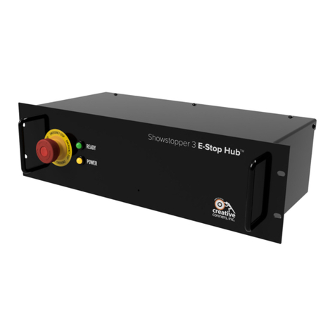
Creative Conners Stagehand Mini2 User manual

creativeconners, inc.
Stagehand Mini
2
Manual
Version 1.0
Copyright © 2014. Creative Conners, Inc. All rights reserved.

Stagehand Mini2Manual
Page 2

Stagehand Mini2Manual
Page 3
TableofContents
GettingStarted..........................................................................................................................................................4
What’sinthebox?.................................................................................................................................................4
StagehandMiniFeatures.......................................................................................................................................5
Installation...............................................................................................................................................................11
RackMount.........................................................................................................................................................11
ElectricalConnections.............................................................................................................................................11
PowerInputConnection......................................................................................................................................11
Showstopper(EmergencyStop)Connection........................................................................................................12
EncodersandLimitsConnections........................................................................................................................13
EthernetConnection............................................................................................................................................19
UsingtheStagehand................................................................................................................................................23
JogtheMotor......................................................................................................................................................23
BrakeTesting...........................................................................................................Error!Bookmarknotdefined.
Auto‐Tuning.............................................................................................................Error!Bookmarknotdefined.
UnderstandingtheStatusDisplay.......................................................................................................................24
SetanIPAddressforSpikemarkCueing..............................................................................................................26
BatteryBackupforEncoderPosition...................................................................................................................27
Troubleshooting......................................................................................................................................................28
CommonProblems...............................................................................................................................................28
TechnicalSupport................................................................................................................................................29
Specifications...........................................................................................................................................................31
ElectricalSpecifications.......................................................................................................................................31
PerformanceSpecifications.................................................................................................................................32
PhysicalSpecifications.........................................................................................................................................33
DefaultMitsubishiParameters................................................................................Error!Bookmarknotdefined.
PLCLadderforMitsubishi........................................................................................Error!Bookmarknotdefined.
WiringDiagram...................................................................................................................................................33

Stagehand Mini2Manual
Page 4
GettingStarted
TheStagehandMini2isthemostversatilecontrollerinourStagehandfamily.TheMini2isbuilttocontrola
widevarietyofmachinesfromsmallDCmotors,tolargebrushlessservomotors,tohydraulicproportional
valves.UnlikeourotherStagehands,theMini2doesnotincludeanybuilt‐inamplifiertopoweramachine
directly,butratheritoutputsastandardizedcontrolsignalthatcanbeusedwithmanythird‐partyamplifiers.
TheMini2packstwoindependentmotioncontrollersinasingle,convenient,3Urackmountenclosure.This
double‐headedapproachallowsyoutocontroltwomachinesfromasingleStagehand,whichisanother
uniquefeatureoftheMini2thatmakesthiscontrolleragreatchoiceformanyshows.
Thismanualwillguideyouthrough:
Unpacking
Installation
Poweringup
Operation
Troubleshooting
Ifyouneedhelpalongthewaycontactusonourwebsite(creativeconners.com),viaemail
([email protected]),orbyphone(401‐289‐2942)
What’sinthebox?
Insidetheboxyoushouldfind:
Referencemanual(thisdocument)
StagehandMini2motioncontroller
Two(2)controlcordsforconnectingtheMini2toyouramplifier
LockingIECpowercable
Two(2)D‐Sub15‐pinshortingplugstodisableBrakeFaultandDriveFaultinputs
Ifanyoftheseitemsaremissing,pleasecontactusimmediatelyforareplacement.
Ifyoupurchasedanypowercables,encoders,limitswitches,orotheraccessories,thoseitemsarepackaged
separately.

Stagehand Mini2Manual
Page 5
StagehandMini2Features
TheStagehandMini2isessentiallytwomotioncontrollersbuiltintoasingle3Urackcase.Themotion
controllersareidenticaltothebrainsfoundinsidetheStagehandProandisthemostversatilecontrollerwe
haveeverproduced.Itfeatures:
Figure1
Figure2

Stagehand Mini2Manual
Page 6
TypicalApplications
TheStagehandMini2cannotpoweramachinedirectly.UnlikeourStagehandProAC,StagehandAC,or
StagehandDC,theMini2lacksaninternalpoweramplifieroptinginsteadtooutputlow‐powercontrolsignals
thatcanbeusedwithalmostanyexternalamplifier.Thisoffersenormousflexibility,atthecostofrequiringyou
tofabricatehousingsfortheamplifieryouwanttouseandthendoabitmorewiringtoconnectthepieces
together.
TherearetwocommonreasonstochooseaStagehandMini2foranautomationproject.Thefirstisthatyou
needtocontrolapieceofequipmentthatcan’tbepoweredbyadedicatedStagehand.Examplesofsucha
machine(asofJuly2014)are:abrushlessdcmotor,anelectro‐hydraulicvalve(servoorproportional),amotor
withahorsepowerratinghigherthan10HP.ThesecondcommonreasontochooseaStagehandMini2isthat
youmayhaveanexistinginventoryofamplifiers(VFD’sorDCregendrives)andwanttopreservethat
investment.Ineithersituation,theMini2isagreatwaytogetyourmachinerunningontheStagehandplatform
andcueitwithourSpikemarksoftware.
TheprimarycontroloutputfromtheStagehandMini2isaspeedsignalandanenablecircuitforeachofitstwo,
independentcontrollers.Theenablecircuitinformstheamplifierwhenitshouldstartlisteningtothespeed
signalsupplypowertothemachinery.Thespeedsignalindicatesbothhowfastandinwhatdirectionthe
machineryshouldmove.
Tosensehowtheamplifierandmachineryarerespondingtothecontroloutput,theMini2expectsaquadrature
encodersignalasinput.Thatsignalisusefulinmeasuringhowfarandfastthemachineryismoving.The
controloutputandencoderinputformtheminimumclosed‐loopsystemthatisrequiredformotion.Any
machine/drivecombinationthatyouconnecttotheMini2mustacceptthecontrolsignalsandprovidean
encodersignalinreturn.
Let’stakealookatsomecommonscenariosthatshowhowthisworksinpractice.Keepinmindthatsincethe
Mini2hastwoindependentcontrollers,youcanhookuptwodifferentmachinestotheMiniandcueeachfrom
Spikemark.
StagehandMini2withaVariableFrequencyDrive(VFD)
WhetheryouhaveanoldVFDthatyou’dliketocontrolwithSpikemark,oryouhaveabrand‐new20HPVFD
yoursystemwilllooksimilartothediagrambelow.

Stagehand Mini2Manual
Page 7
z
Figure3

Stagehand Mini2Manual
Page 8
StagehandMini2withaElectro‐HydraulicValve
Hydraulicsystemshaveaseveralattractivetraitsthatmakethemtemptingtouseonstage.Youcankeepthe
HPU(hydraulicpowerunit)inaremotelocationoutofearshotandrunhosestoactuatorsonstagereducingthe
noiseofthemotiontopracticallynothing.Hydraulicsystemsalsooffertremendouspowertobepackedinto
relativelysmallactuators.However,automatinghydraulicswithprogrammablespeedandpositioninghas
traditionallybeentricky.However,usingaeitheraservovalveorelectricproportionalvalveeitherwithon‐
boardelectronics(OBE)oradiscretevalvedriverandaStagehandMini2makestheprocesspainless…well…if
wearehonesthydraulicsarestillfinickyandabittricky,butatleastitispossiblewithsomeplanningand
patience.
Figure4

Stagehand Mini2Manual
Page 9
StagehandMini2withDCDrive
DCmotorsusedtobeastapleofstageautomation.Althoughtheirpopularityhaswanedovertheyearsas
quieterACinductionmotorsandVFD’shavebecomemoreeconomicalandprovideabettersolutioninmanner
situations.However,thereisstillalotofDCequipmentwithausefullifeleftandusingaMini2tobreathenew
lifeintooldequipmentcanbeagreatwaytoexpandyourautomationcapacity.ThehookupissimilartoaVFD,
withtheadditionofasignalisolatorcardwhichprotectstheMini2fromdangerousvoltagelevels.

Stagehand Mini2Manual
Page 10
Figure5

Stagehand Mini2Manual
Page 11
Installation
TheStagehandMini2hasbeendesignedprimarilyformountinginastandard19”equipmentrack.Itoccupiesa
3Uspacemeasuring5.25”vertically.Foreasyoperation,itismostconvenienttomounttheMini2horizontally,
youcanalsosafelymountitvertically.
Figure6
RackMount
Fortouringapplications,orpermanentinstallationstheStagehandcanberackmountedinastandard19”
equipmentrackusingtheincludedmountingears.However,therackmustbeorientatedhorizontallysothat
theStagehandremainsverticalintherackforproperheatventilation.
ElectricalConnections
OncetheMini2isinstalledinyourrackit’stimetotakealookatthebacksideofthecaseandfigureoutallthe
electricalconnections.
PowerInputConnection
ThepowerinletisastandardIECC14cordlikemanyconsumerelectronics(computers,projectors,TV’s,etc).
Thepowerinlethasasmallfusecompartmentnexttothecordthatslidesoutforeasyreplacement.
Figure7
IncludedwithyourStagehandMini2isa6’powercordwithalockingIECconnectorononeendandanEdison
plugontheother.Thelockingconnectorpressesontothepowerinletandautomaticallylocksintopositionto

Stagehand Mini2Manual
Page 12
resistaccidentallykickingthecordoutandlosingpower.Toreleasethelockingconnector,pullbackonthe
orangetabandthenpullthecordoutoftheinlet.
Figure8
Showstopper(EmergencyStop)Connection
TheStagehandMini2requiresa24vdcEmergencyStopsignalfromaShowstoppertoallowanymotionsignalsto
beoutputtoyourmachineamplifier.Internally,theStagehandMini2hasaredundant,self‐monitoringcircuitto
insurethatpowerwillberemovedfromtheamplifierenablesignalinstantlyifthe24vdcEmergencyStopsignal
isinterrupted.However,sincetheMini2doescontrolpowerdirectlytotheamplifier(VFD,DCdrive,valve
driver,etc.)youmustinstallappropriatesafetycontactorstointerruptpowertoyourexternalamplifier.The
externalsafetycontactorsthatyouinstallinyouramplifierenclosureshouldbesignaledbythesame
ShowstopperthatisconnectedtotheMinisothatbothdevicesarecontrolledbythesameEmergencyStop
signal.Hereisanexample,bearinmindthatyoumustimplementthesafetycircuitryappropriateforyour
application.

Stagehand Mini2Manual
Page 13
Figure9
Beforeyoucanmoveanymachine,youmustconnecttheStagehandtoaShowstopperwitha5‐pinXLRcable.
The5‐pinXLRcableisnotaDMXsignal,butratheritwaschosenasaconvenientcablethatisprevalentinmany
venuessoyoushouldalwaysbeabletofindasparecablewhenneeded.
Belowisthepin‐outfortheShowstopperEmergencyStopinput:
Figure10
EncodersandLimitsConnections
Twosetsofencodersignals(oneforspeedmonitoringandoneforpositioning)andthreesetsoflimitswitches
(forward,reverse,andultimate)arecombinedinonerectangularconnector(Hartingconnector:#09160243101,
Hartingplug:#09160243001).

Stagehand Mini2Manual
Page 14
AlllimitswitchsignalsrequireNormallyClosed(N.C.)switches.TheStagehandsources12vdconapinofthe
eachlimitcircuitandexpectstoseethat12vdcsignalreturnedontheotherpinwhenthelimitisnotactivated.
Ifthelimitiseitheractivatedordisconnectedorawiringfaultoccurs,the12vdcreturnsignalisliftedandthe
Stagehandwillenteralimitfaultconditionanddisallowmotion.
Thelimitswitchinputsareusedtoprotectagainstthemotortravelingtoofarinadirectionandcausingdamage
orinjury.Whenrunninginacue,thisisoneofthesafetyfeaturesthatguardsagainstencoderfailure.When
joggingmanually,thiskeepsyoufromaccidentallytravelingtoofar.
Allencodersignalsusedifferentiallinereceiverswhichuseabalancedsignaltransmittedovertwisted‐pairwires
todrasticallyreduceelectricalinterferenceandthusreducetheopportunityforinaccurateencoderdata.
EncodersconnectedtotheStagehandmustbeequippedwithdifferentiallinedriverstobecompatible.
Encodersarepoweredat5vdcforbroadestcompatibility.
Figure11
Let’sstartwiththelimitsignals:
UltimateLimit–apairofNormallyClosed(N.C.)switchescanbewiredinseriestothispairofterminals
toprovideprotectionagainstForwardandReverseLimitswitchfailures.Typically,anUltimateLimit
switchispositionedjustbeyondboththeForwardandReverseLimitswitch.IfanUltimateLimitis
activated,theStagehandwilldisallowanyfurthermovementuntilthelimitisphysicallycleared.In
normaloperation,thereisneverareasontostrikeanUltimateLimit.AnUltimateLimitsignalindicates
anequipmentproblemwithatleastoneoftheprimarylimitswitches.Thefaultyequipmentmustbe
repairedandtheUltimateLimitmustbemechanicallyresetbeforetheStagehandwillallowmotion.

Stagehand Mini2Manual
Page 15
ReverseLimit–aNormallyClosed(N.C.)switchcanbewiredtothispairofterminals.Iftheswitchis
activated,theStagehandwillnotallowfurthermotioninthereversedirectionuntilthelimitiscleared
eitherbyadjustingtheswitchmechanicallyorbymovingintheforwarddirectionfarenoughtoclearthe
limitswitch.
ForwardLimit–aNormallyClosed(N.C.)switchcanbewiredtothispairofterminals.Iftheswitchis
activated,theStagehandwillnotallowfurthermotionintheforwarddirectionuntilthelimitiscleared
eitherbyadjustingtheswitchmechanicallyorbymovinginthereversedirectionfarenoughtoclearthe
limitswitch.
SincetheStagehandprovidesthree(3)separatepinsthatallsource12vdc,oneforeachlimitsignal,youcan
reducethewiringinyourmachinetofour(4)wiresbyusingjustoneofthe12vdcsourcepinsandthree(3)
wiresforthethreelimitreturnsignals.Sometimesitismoreconvenienttowireapairofconductorsfor
eachswitch,othertimesitmaybebettertoreducethenumberofconductorsbysharingacommonvoltage
source.Bothoptionsareshownbelow:
Figure12

Stagehand Mini2Manual
Page 16
Figure13
Nowlet’stakealookattheencodersignals:
SpeedEncoder(optional)–asetofquadraturesignalsthatcanusedbytheVariableFrequencyDrive
(VFD)toaccuratelyregulatespeed.Internally,theStagehandMini2doesnotusetheSpeedEncoderbut
thepinsareavailabletouseifyouhaveaVFD(orotheramplifier)thatcanusethesignalfortighter
speedregulation.
PositionEncoder–asetofquadraturesignalsusedbythemotioncontrollertodrivethemotorto
correctpositionsoncue.ThisencodermaybethesameastheSpeedEncoderoritmaybeaseparate
encoder.Forinstance,ascissorliftthatisdrivenbyavariable‐speedpumpneedsaspeedencoderon
thepumpmotor,butthepositioningencodershouldbeplaceddirectlyontheliftplatformsince
relationshipbetweenthemotorrotationandplatformpositionchangesdependingontheextension
heightoftheliftasitraisesandlowers.Adeckwinchhowever,canuseasingleencodermountedon
themotorforbothspeedandpositioning.
Asmentionedabove,youcanuseeitherasingleencodermountedtothemotorforbothSpeedandPosition
Encodersignals,orseparateencodersmountedindifferentlocationsonthemachine.Belowaretwodrawings
thatshowhowtowireyourencodersignalsinbothscenarios:

Stagehand Mini2Manual
Page 17
Singleencoder:
Figure14

Stagehand Mini2Manual
Page 18
Dualencoders:
Figure15

Stagehand Mini2Manual
Page 19
EthernetConnection
TocommunicatewithSpikemarkandruncuesinashow,theStagehandneedstobeconnectedtoanetwork.
LocatedonthebacksideoftheStagehand,theEthernetinputwillacceptaCAT5networkcablewitheithera
traditionalRJ45plugoraRJ45plugwithaNeutrikEtherconshellinstalled(MouserPart#568‐NE8MC‐B).The
EtherconshellisanXLRhousingthatslipsoveranetworkcabletoprovideadditionalstrainreliefandapositive‐
lockconnectionthatmakesitpreferredbackstage.
Figure16
ControlSignalOutput
Figure17

Stagehand Mini2Manual
Page 20
Serial(DB9)
TheMini2hasDB9plugstosupportupcomingaccessoriesthatoperateoverRS‐232serial.Theconnectionsare:
PinNumber Connection
2 SerialReceive
3 SerialTransmit
5 SerialCommon
9 +5VDC
DriveComm(HD15)
TheMini2has15‐pinhigh‐densityD‐Subconnectorthatsupportafewniftyfeatures,somearecurrentlyusedin
ourSpikemarkcueingsoftwareandothersgiveaccesstoupcomingcapabilities.
PinNumber Connection
1 DriveReadyInput
2 BrakeFaultInput
3 InputCommon
4 AuxOutput1(120mAN.O.)
Table of contents
Other Creative Conners Controllers manuals