Creative Conners Spikemark Pendant User manual

Spikemark Pendant
User Manual V1.0

Rev 12-31-2018
TABLE OF CONTENTS
TABLE OF CONTENTS 2
GETTING STARTED 4
FEATURES 4
SETUP 4
MAKING THE CONNECTIONS 4
NETWORK SETTINGS 5
PENDANT SETTINGS 5
SPIKEMARK SETTINGS 5
Confirm the computer IP Address 6
Pendant Configuration 7
OPERATION 11
STARTUP AND SHUTDOWN 11
UNDERSTANDING THE DISPLAY 13
STATUS ICONS AND AXIS DETAILS 13
MANUAL JOG 16
JOG WITH THE PADDLE 16
JOG WITH THE JOG WHEEL 17
GROUP JOGGING 17
JOG TO A SPIKE 18
TECHNICAL SUPPORT 18
TROUBLESHOOTING 18
OPERATIONAL ISSUES 18
WILL NOT MOVE TO A SPIKE 19
UNABLE TO MANUALLY JOG 19
TOUCHSCREEN 19
CASE, BUTTONS AND SWITCHES 19
CONNECTION ISSUES 19
SPECIFICATIONS 23
ELECTRICAL 23
PHYSICAL 24
Weight 24
DRAWINGS 25
Page 2 of 24

Rev 12-31-2018
GETTING STARTED
The Pendant works in conjunction with Spikemark and the Showstopper 3 Base to bring the power of
Spikemark to anywhere in the theater. Once connected to Spikemark, you are no longer tied to the
automation table!
Although the Pendant is portable, it is not indestructible - it’s a little computer after all. Take care to
avoid dropping the Pendant, spilling liquids on it and scratching the touch screen.
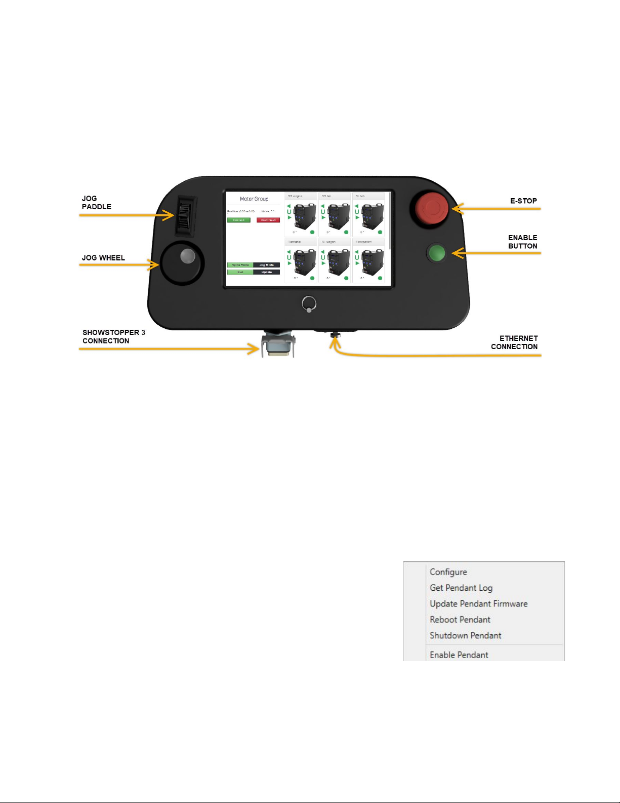
FEATURES
●7” Touchscreen
●Network connected device
●Rugged locking cable connectors
●Self terminating Remote E-Stop button
●Factory set with Hold To Run (HTR) functionality
●Jog any motor manually or to a Spike
●Jog motor groups manually
●Use the jog wheel for fine tuning position
●Adjust Spikes on the fly
●Bluetooth keyboard for adjusting default settings
SETUP
The Pendant communicates with Spikemark through the same network the Stagehands use. It is not
a stand alone controller, but an arm of Spikemark. Setting up the Pendant is straightforward, with
only two cable connections and a few IP Addresses you’ll be up and running in no time.
MAKING THE CONNECTIONS
The Pendant has two physical connections:
●Showstopper 3 Accessory input
●Network input
The Accessory input provides power to the Pendant as well as the Remote E-Stop capability. This
connection is a standard Showstopper 3 Accessory cable connector, a male Harting style 6B locking
connector. The Pendant is self terminating, meaning it will be the final accessory in that line. It can
be connected to the system through the Stage Manager or any open Accessory port on a
Showstopper 3 Base or Hub.
Network connectivity is provided through a Neutrik EtherCon receptacle. We like these connectors
due to their ruggedness but don’t worry if you only have a standard RJ45 cable - they plug right in as
well. Once the physical connections are complete, it’s time to set up the network properties.
Page 3 of 24

Rev 12-31-2018
NETWORK SETTINGS
Because the Pendant is a networked device, it needs to have a unique IP address. This address
needs to be set on both the Pendant and Spikemark in order to allow communication.
PENDANT SETTINGS
Once the connections are made and there is power to the Showstopper 3 Base the Pendant will be
powered on.
Once the boot up process is complete the Pendant will be at the IP Address screen.
The default IP Address values will already be filled in for both the computer running Spikemark as
well as the Pendant:
●Spikemark IP: 192.168.10.245
○This is the IP Address of the computer running Spikemark
●Pendant IP: 192.168.10.250
○This is the IP Address of the Pendant
●Subnet Mask: 255.255.255.0
●Port: 8080
You can use the jog wheel or the Bluetooth keyboard, which shipped with the Pendant, to adjust any
of these values. Any changes to the IP Addresses, Subnet or Port will be saved to the Pendant once
the Connect button is pressed.
SPIKEMARK SETTINGS
If you have set up a Stagehand in the past, setting up the Pendant IP Address will feel familiar though
a bit more involved.
Page 4 of 24

Rev 12-31-2018
Confirm the computer IP Address
Before moving forward you will need to confirm the Spikemark computer IP Address matches what is
entered on the Pendant. To find your network settings in Windows 10:
●Press the Start button, type Network Status
then press Enter
●On the Network Status window click on “View your network properties”
Page 5 of 24

Rev 12-31-2018
●Find your network adapter (if you have more than one) and find the IPv4 address
In this case I am using the Surface Ethernet Adapter and the IP address is 192.168.10.245
●If you need to adjust your IP address, click the back arrow in the upper left corner, then click
“Change adapter options”
○Double click on your adapter from the list
○Double click on Internet Protocol Version 4 (TCP/IPv4)
○Click “Use the following IP address” radio button
○Adjust the IP address
○Confirm the Subnet mask is 255.255.255.0
○Click OK to close the settings window
○Click OK to close the adapter properties window
○Close the Network Connections window
○Close any additional windows
Pendant Configuration
1. Confirm Enable Pendant is unchecked
Page 6 of 24

Rev 12-31-2018
2. Select Configure from the Pendant menu
3. In the Pendant Configuration window, enter the computer and pendant IP Addresses (if
different from the default) and click OK
Page 7 of 24

Rev 12-31-2018
4. Select Enable Pendant from the Pendant menu
5. Select Connect on the Pendant menu
Page 8 of 24

Rev 12-31-2018
6. Once the Pendant is connected the display will change from the set-up screen to the
operation interface.
Page 9 of 24

Rev 12-31-2018
OPERATION
Once the Pendant and Spikemark are communicating you are ready to go. Before you Make It Move!
let's take a look at the Pendant buttons, levers and knobs:
STARTUP AND SHUTDOWN
The Pendant will power up as soon as it is plugged into an active Showstopper 3 Accessory port.
However it must be enabled every time Spikemark is started before it will be able to connect.
The Pendant menu within Spikemark has several options:
➔Configure
◆IP Address and Port configuration
➔Get Pendant Log
◆Downloads the log to your PC - great for
troubleshooting!
➔Update Pendant Firmware
◆Firmware updates are executed from here
➔Reboot Pendant
◆The preferred reboot method
➔Shutdown Pendant
◆The preferred shut down method
➔Enable Pendant
◆Enabling the Pendant in Spikemark
Page 10 of 24

Rev 12-31-2018
To shut down the Pendant, select Shutdown Pendant from Spikemark. Once the Pendant display is
blank it is safe to unplug the Pendant.
Occasionally the Pendant will need to be rebooted. Select Reboot Pendant from Spikemark, once
rebooted reconnect from the Pendant display.
IMPORTANT NOTE: If the Pendant is unresponsive you will need to pull the accessory cable to
restart. This method requires the Pendant to be unplugged for approximately 45 seconds before it
will restart
When updated firmware is released, it can be installed to the Pendant from Spikemark by clicking
Update Pendant Firmware.
If you encounter issues while using the Pendant select Get Pendant Log and follow the prompts.
Once downloaded to your computer email the Pendant log, along with the current show file and the
last three Spikemark logs to [email protected].
Page 11 of 24

Rev 12-31-2018
UNDERSTANDING THE DISPLAY
The Pendant screen displays a wealth of information to the operator and is easy to navigate with the
touch of your finger. Let’s take a look at the typical screen layout.
The Axis Selection area will be populated with any Stagehands in your show file. If your show only
has one axis, you will only see one motor displayed. If you are working with more than six axes you
can scroll down with the scroll bar or slide the axes up to see additional units.
Each axis is populated in the order which Spikemark connects to the Stagehand. This means that
each time you connect the Pendant, the display order of axes could be different.
STATUS ICONS AND AXIS DETAILS
Each Axis has several status icons which identify the connection state as well as the primary and
ultimate limit conditions.
Page 12 of 24

Rev 12-31-2018
AXIS STATUS ICONS
AXIS LIMIT STATES
The Spikes section displays the state of the spikes.
Page 13 of 24

Rev 12-31-2018
SPIKES DISPLAY PARTS
SPIKES HIGHLIGHT COLORS
Jogging to a Spike outside the soft limits will
only jog to the programmed soft limit.
Spikes can be updated from the Pendant or in
Spikemark
Page 14 of 24

Rev 12-31-2018
MANUAL JOG
With Spikemark and the Pendant communicating and an understanding of the interface under your
belt, it’s time to Make It Move!
The Pendant is able to manually jog any single or grouped axis with
the Paddle or the Jog Wheel. You can also dive into a Group to manually nudge a single motor as
needed. See the images below for details.
MANUAL JOG SELECTION OPTIONS
No matter the manual jog method, the ENABLE button must be pressed and held in order to allow
motion.
JOG WITH THE PADDLE
Jogging with the Paddle is the quickest way to move the selected axis or group. The Paddle offers
proportional control of the selected axis - the further you move the paddle the faster the axis will go.
This is really helpful when moving scenery on stage for spacing and placement. As with the
Showstopper 3 Consolette and the Spikemark on-screen jog slider, the Paddle has a non-linear jog
profile, making jog moves smooth through the full range of motion. Here’s how to jog with the
paddle:
●Select the axis or group
●Select Jog Mode then select Paddle
Page 15 of 24

Rev 12-31-2018
●Press and hold the green Enable Button
●Move the jog paddle forward or reverse to move the selected axis in that direction
JOG WITH THE JOG WHEEL
Jogging with the Jog Wheel works the same way on the Pendant as it does with the Showstopper 3
Consolette. Depending on the setting, one click of the wheel will move the selected axis one scaled
unit or 1/10th of one scaled unit. This means if you are jogging a Pushstick with a scaled position in
Inches, one click of the jog wheel will move the Pushstick 1” when Coarse is selected or 0.1” when
Fine is selected. Here’s how to jog with the Jog Wheel:
●Select the axis or group
●Select Jog Mode then select Coarse or Fine
●Press and hold the green Enable Button
●Turn the jog wheel Clockwise to move forward and Counterclockwise to move reverse
●The status will show the move distance
GROUP JOGGING
Jogging a group works the same as jogging an individual axis. To manually jog a group, simply
select the group in the axis selection area and follow the instructions above. If you need to jog an
individual motor in a group you can do that as well. Click on the arrow icon to drill down into the
group. Once the group is open, select the axis to move and jog with the paddle or wheel.
Expand Group
Jogging individual motors in a group
Page 16 of 24

Rev 12-31-2018
JOG TO A SPIKE
In addition to manual jog capabilities, the Pendant allows jogging to a specified Spike. These are the
same Spikes as in Spikemark. If the selected axis doesn't have any spikes set or if you have a Group
selected no spikes will be available. Keep in mind that jogging to a Spike utilizes the Default Speed
and Acel values in Spikemark for that axis. To jog to a Spike:
●Select the axis
●Select the Spike to move to - it will highlight RED
●Press and hold the Enable button. The selected Spike will highlight GREEN
●When the move is complete the Spike will highlight BLUE
●Jogging to a Spike is only supported on individual axes
TECHNICAL SUPPORT
We strive to provide all the details required to operate and troubleshoot issues here. But if you are
stuck and getting frustrated have no fear, we are here to help! The best and quickest way to reach
us is via email: [email protected]. Someone is on call,
weekdays/evenings/showcall/weekends to get back to you quickly. We are also here to talk - call us
at 401-289-2942 x2. If we don't answer we'll call you back.
TROUBLESHOOTING
OPERATIONAL ISSUES
Page 17 of 24

Rev 12-31-2018
WILL NOT MOVE TO A SPIKE
Occasionally you may not be able to jog to a Spike, yet will still be able to manually jog. This is a
communication issue between the Pendant and Spikemark. Rebooting Spikemark and reconnecting
the Pendant will restore full functionality.
UNABLE TO MANUALLY JOG
●Confirm jogging functionality from a Showstopper 3 Consollette or from the manual jog
controls in Spikemark
●Confirm the green ENABLE button is engaging.
●Restart Pendant
●Restart Spikemark
TOUCHSCREEN
1. Screen unresponsive
a. Reboot Pendant from Spikemark
b. Hard reset (remove power, wait three minutes)
c. Email [email protected]
2. Screen damaged/broken
a. Email [email protected]
CASE, BUTTONS AND SWITCHES
1. Case is broken
a. Email [email protected]
2. Broken switch, knob or lever
CONNECTION ISSUES
1. Pendant connects but is not functioning properly
a. No machine selection
b. No jogging, manually or to a Spike
i. There is a Router acting as a DHCP server on the automation network and is
causing communication issues. Solution:
1. Remove the Router from the system and try again
2. Showstopper Accessory connector is damaged
a. Email [email protected] for instructions
3. EtherCon connector is damaged
a. Email [email protected] for instructions
4. Pendant will not connect.
a. Confirm the Pendant is enabled in Spikemark
b. Confirm IP Address and Port settings match on Pendant and in Spikemark
c. Confirm Ethernet Cable is connected
d. Attempt reconnecting
Page 18 of 24

Rev 12-31-2018
5. Pendant screen displays “Enable Pendant in Spikemark”
a. Follow all steps in steps in section 1 above
b. Confirm the port is available and open thru Windows Defender Firewall
i. See section 3 below for details
c. Disable all 3rd party firewall programs
i. Macfee and Norton firewalls are both known to block the Pendant
communication
6. Pendant screen displays “Network error”
a. Pendant screen will initially flash when attempting to connect, then displays “Network
Error”.
i. On subsequent attempts to connect, status will switch to “Connecting” for
approximately 1 second or less, then switch back to “Network Error.”
b. Open Windows Defender Firewall with Advanced Security
i. Press the Start key and enter Windows Defender Firewall
and press Enter
ii. Select Inbound Rules
on the left and scroll through the Inbound Rules list to
find“Spikemark_Pendant_Port”
Page 19 of 24

Rev 12-31-2018
1. If there are multiples, delete all but two of them.
2. If there is only one, right click on “Spikemark_Pendant_Port” and select
“Copy”, then right click on it again, and select “Paste”. Can also left click
to select and use Ctrl+C to copy and Ctrl+V to paste. It will paste at the
top of the list, so either scroll up to find it, or resort via Name or Group by
clicking on the corresponding column header.
iii. Double click the second “Spikemark_Pendant_Port” to open the Properties
panel and select the “Protocols and Ports” tab at the top.
Page 20 of 24
Table of contents
Popular Remote Control manuals by other brands

Heinner
Heinner HAC-HS09KIT++ manual

Vestamatic
Vestamatic VRS Transmitter 5C Installation and operating instructions

Archer Components
Archer Components TRAIL D1X Installation

Kirkland Signature
Kirkland Signature KS562-DRW user guide

Scientific Atlanta
Scientific Atlanta AT8450 user guide

FUTABA
FUTABA T10J instruction manual