1deutsch
BAE PS-XA-3Y-24-250-609-I / BAE PS-XA-3Y-24-250-611-I
Netzgeräte
Zu dieser Anleitung
Diese Anleitung stellt alle benötigten Informationen bereit
für den Einbau und Anschluss der Netzgeräte.
Sie gilt für folgende Typen:
– BAE PS-XA-3Y-24-250-609-I
Bestellcode: BAE012P
– BAE PS-XA-3Y-24-250-611-I
Bestellcode: BAE012R
Bestimmungsgemäße Verwendung
Das Netzgerät ist für das 3-Phasen-Netz und für den
Einsatz in Innenräumen im Industriebereich vorgesehen. Es
ist geeignet für die Versorgung aus TN-, TT- oder IT-Net-
zen.
Die einwandfreie Funktion gemäß den Angaben in den
technischen Daten wird nur dann zugesichert, wenn das
Produkt ausschließlich wie in der Betriebsanleitung und
den mitgeltenden Dokumenten beschrieben sowie unter
Einhaltung der technischen Spezifikationen und Anforde-
rungen und nur mit geeignetem Original Balluff Zubehör
verwendet wird.
Andernfalls liegt eine nichtbestimmungsgemäße Verwen-
dung vor. Diese ist nicht zulässig und führt zum Verlust von
Gewährleistungs- und Haftungsansprüchen gegenüber
dem Hersteller.
Vernünftigerweise vorhersehbare Fehlanwendung
Das Produkt ist für folgende Anwendungen und Bereiche
nicht bestimmt und darf dort nicht eingesetzt werden:
– im Außenbereich
– in sicherheitsgerichteten Anwendungen, in denen die
Personensicherheit von der Gerätefunktion abhängt
– in explosionsgefährdeten Bereichen
– im Lebensmittelbereich
Mitgeltende Dokumente
Eine ausführliche Betriebsanleitung und weitere Informatio-
nen zu diesem Produkt finden Sie unter www.balluff.com
auf der Produktseite.
Sicherheitshinweise
Tätigkeiten wie Einbau, Anschluss und Inbetriebnahme
dürfen nur durch geschulte Fachkräfte erfolgen.
Eine geschulte Fachkraft ist, wer aufgrund seiner fachli-
chen Ausbildung, seiner Kenntnisse und Erfahrungen
sowie seiner Kenntnisse der einschlägigen Bestimmungen
die ihm übertragenen Arbeiten beurteilen, mögliche Gefah-
ren erkennen und geeignete Sicherheitsmaßnahmen treffen
kann.
Der Betreiber hat die Verantwortung, dass die örtlich
geltenden Sicherheitsvorschriften eingehalten werden.
Insbesondere muss der Betreiber Maßnahmen treffen,
dass bei einem Defekt des Produkts keine Gefahren für
Personen und Sachen entstehen können.
Das Produkt darf nicht geöffnet, umgebaut oder verändert
werden. Bei Defekten und nichtbehebbaren Störungen des
Prokukts ist dieses außer Betrieb zu nehmen und gegen
unbefugte Benutzung zu sichern.
Sicherheitshinweise (Fortsetzung)
Das Produkt darf nicht geöffnet, umgebaut oder verändert
werden. Bei Defekten und nichtbehebbaren Störungen des
Prokukts ist dieses außer Betrieb zu nehmen und gegen
unbefugte Benutzung zu sichern.
Die Membran auf der Rückseite des Geräts (Aluminiumge-
häuse) ist eine funktions- und sicherheitsrelevante Kompo-
nente und darf unter keinen Umständen beschädigt oder
entfernt werden.
Das Gerät ist ausgelegt Für TN,TT-Netze mit geerdetem
Neutralleiter und IT-Sternnetze mit Isolationsüberwachung
sowie für Zonen der ÜberspannungskategorieIII bis zu
2000m (6560ft) und für Zonen der Überspannungskate-
gorie II bis zu 5000m (16400ft). Für TN-, TT-, IT-Delta-
Netze oder IT-Stern-Netze ohne Isolationsüberwachung ist
das Gerät für die ÜberspannungskategorieII bis zu einer
Höhe von 2000m (6560ft) vorgesehen. Das Gerät ist so
ausgelegt, dass es auch bei einem einphasigen Ausfall
sicher ist und benötigt keinen externen Schutz. Die Funkti-
onalität ist dann jedoch eingeschränkt. Das Gerät ist für
Höhen bis zu 5000m (16400ft) ausgelegt. Über 2000m
(6560ft) ist eine Reduzierung des Ausgangsstroms erfor-
derlich und der Betrieb ist entsprechend den oben
beschriebenen Netzsystemen eingeschränkt.
Das Gehäuse des Geräts bietet einen Schutzgrad von
IP65/67, wenn es mit allen Gegensteckern fest verbunden
ist. Das Gerät ist für Bereiche mit Verschmutzungsgrad 3 in
kontrollierten Umgebungen ausgelegt. Bei der Installation
dürfen keine Feuchtigkeit oder Schmutz in die Anschlüsse
gelangen.
Heiße Oberflächen
Das Gehäuse erwärmt sich unter normalen Betriebsbedin-
gungen. Es besteht die Gefahr von Brandverletzungen.
Direkten Hautkontakt mit der Oberfläche vermeiden.
Funktion
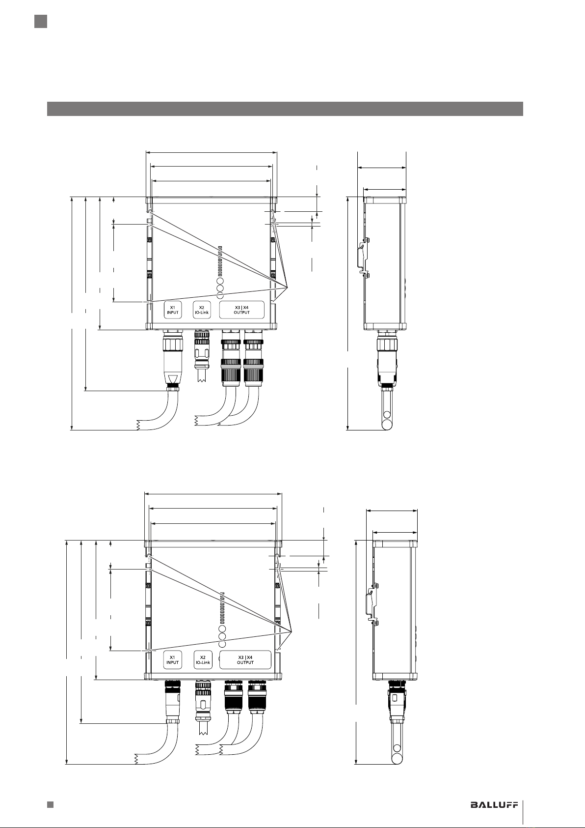
Eingang (X1)
Das Gerät ist geeignet für die Versorgung aus TN-, TT-
oder IT-Netzen und einen Dauerbetrieb von
3×380…480V (±15 %)AC.
Das Netzteil nicht mit DC-Eingangsspannung betrei-
ben!
IO-Link-Anschluss (X2)
Die IO-Link-Schnittstelle entspricht dem IO-Link-Protokoll
V1.1 und ermöglicht einen transparenten Datenfluss und
eine Überwachung des aktuellen Status der Stromversor-
gung.
DC-Ausgang (X3/X4)
Die Ausgänge liefern eine Nennspannung (PELV/ES1), die
von der Eingangsspannung galvanisch getrennt ist. Das
negative Potential der Ausgänge ist im Gerät fest mit PE
verbunden (keinen Ausgang an PE (Masse) anschließen!).