Spezialelektronik GmbH
Bautzner Landstr. 23 http://www.iseg-hv.de Fax ++ 49 (0) 351 / 26 996 - 21
D - 01454 Radeberg/ Rossendorf 7
3. Technical Data
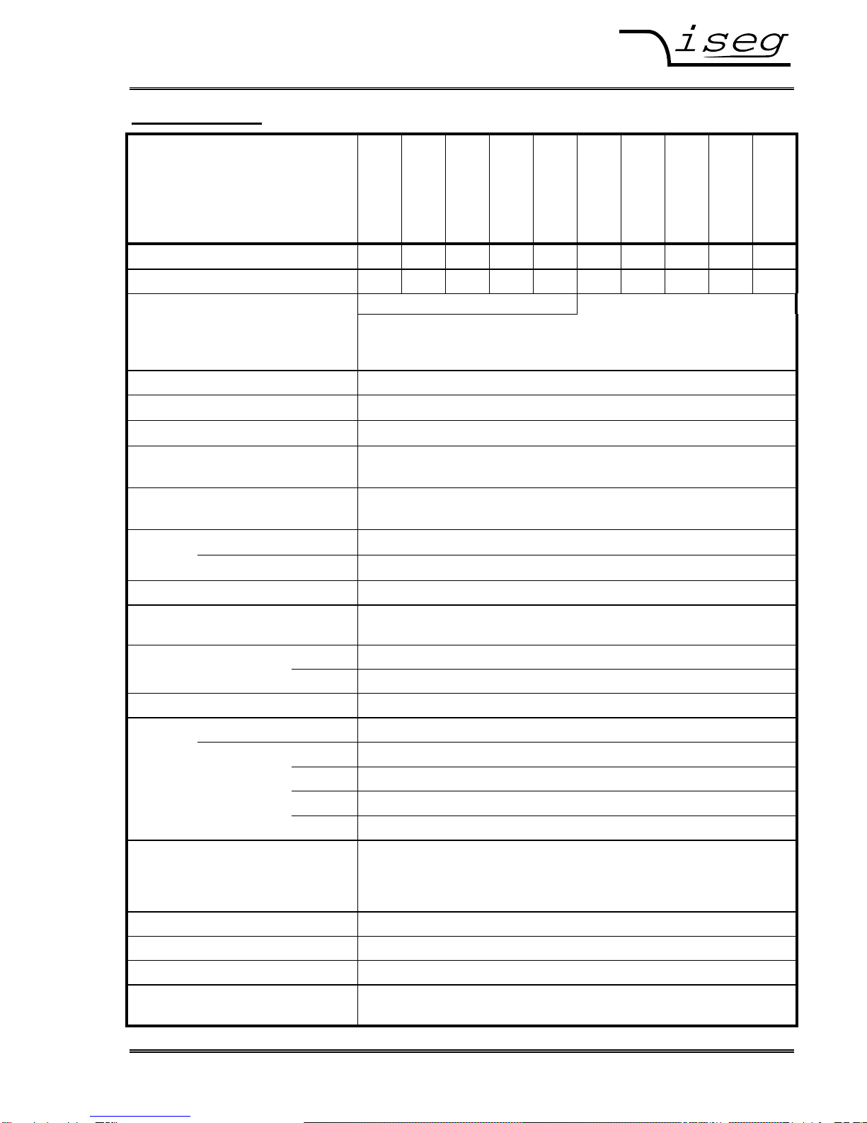
19“ / 1U - series HPx)1 300 W
HPx)1 10 307
HPx)1 20 157
HPx)1 30 107
HPx)1 40 756
HPx)1 60 506
HPx)1 80 356
HPx)1 120 256
HPx)1 150 206
HPx)1 200 156
HPx)1 300 106
Output voltage VOUT max [kV] 1 2 3 4 6 8 12 15 20 30
Output current IOUT [mA] 300 150 100 75 50 35 25 20 15 10
HV-connector SHV front side (opt. rear side) Lemo-HV-connector rear side
V
OUTmax ≤16kV: Lemo ERA.1Y.416.CLL
V
OUTmax > 16kV: Lemo ERA.3Y.425.CLL
Attention: Use with connected HV connector only !
Output power max. 300 W
Polarity Factory fixed ⇒)1x = p: positive ⇒)1x = n: negative
Ripple & noise < 1 ∗10-4 ∗VOUTmax (VP-P)
Voltage stability < 1 ∗10-4 ∗VOUTmax (load to no load, ∆VIN and repeatability)
in the output voltage range: 5 V ≤VOUT ≤VOUTmax
Current stability < 2 ∗10-3 ∗IOUTmax ( RLmin ≤RL< no load and ∆VIN)
in the output voltage range: 5 V ≤VOUT ≤VOUTmax
Accuracy voltage measurement ± (0,05% ∗Vout + 0,02% ∗Vout max + 1 digit) for one year
current measurement
± (0,05% ∗Iout + 0,02% ∗Iout max + 1 digit) for one year
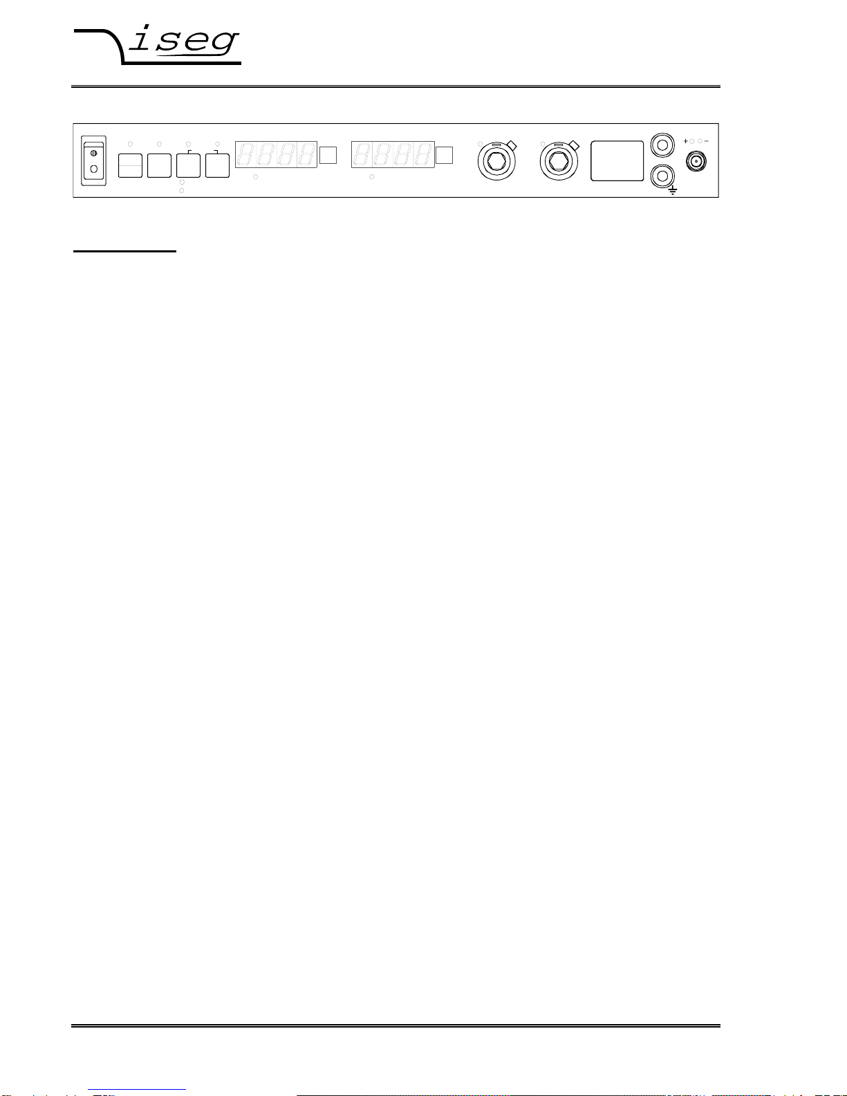
Display 4-digit LED-Display for current and voltage
Resolution of voltage and current
measurement via Interface: VOUTmax / 50000 via Display: limited to 4 digit
I
OUTmax / 50000
Resolution of settings LOCAL VOUTmax / 2000 and IOUTmax / 2000
Voltage / Current REmote VOUTmax / 50000 and IOUTmax / 50000
Switching of output voltage with button “ON/OFF” or via remote control
Control LOCAL 10-turn potentiometer for voltage and current
(REMote) CAN via CAN-Interface (also for diagnosis / software update)
RS232 via RS232-Interface
optional: aIF via indirect coupled analogue I/O instead of RS232-Interface
optional: IEEE via IEEE-Interface additionally
Supply VIN = 85 up to 264 V-AC with PFC
IIN = 1,7 A at 230V-AC / 3,5 A at 115 V-AC
via mains connector and switch “POWER“, isolated from HV-output,
fused with 2 ∗6,3 A / slow.
Dimension / Weight 1U -19“ compatible / depth: 450 mm / ca. 5,7 kg
Cooling Internal fan
Protection Over load and short circuit , voltage supply and temperature
Environment conditions Operating temperature: 5 up to 35 °C
Humidity: 30% up to 80 %, no condensation