Creative Lighting Solutions CLS Zense User manual
CLS Manuals
CLS Zense
www.cls-led.com
version 2.3 November 2010
www.cls-led.com
- 1 - - 2 -
CLS Zense
INTRODUCTION
The CLS Zense is a DMX controller specially designed for LED applications. It supports up to 5 colour
control with or without a master channel. Besides the DMX, the CLS Zense is also able to directly drive
voltage-controlled LED products, such as Colourcove X-bright, Manon single colour and RGB, Safestairs etc.
The CLS Zense is designed to fit in the most common wall mount fittings. This makes the CLS Zense very
easy to install. The universal connection possibilities make it perfect for every installation. Because the CLS
Zense uses Capsense technology, the surface is totally flat.
Included items
The CLS Zense is shipped in one package containing the following items:
• 1 x CLS Zense
• 1 x manual
• 1 x black frame
• 1 x white frame
• 1 x power supply & 4 plugs (VDE + UL & PSE + SAA + BS)
• 1 x RJ45 to PWR cable
• 1 x RJ45 to XLR cable
• 1 x 3-way connection block RJ45
• 1 x UTP-CAT5 cable, 2mtr
Protection from burns and fire
• Do not install the CLS Zense near a heat source.
• Do not install the CLS Zense in a corrosive, flammable or explosive area.
• Do not modify the CLS Zense, or install other than genuine parts.
• Do not operate the unit if the ambient temperature exceeds 40 ºC.
• Operate in a well ventilated area
Protection from injury due to falls
• Verify that all covers and mounting hardware are securely fastened.
• Block the access below the work area whenever installing or removing the unit.
Protection from electric shock
• Disconnect the power supply from AC power before installing, dismounting or maintaining the unit.
• Make sure all connectors are connected properly.
• Use only a source of AC power that complies with local building and electrical codes.
• Do not expose the unit to rain or moisture.
• Refer all service to a qualified technician.
Note: It is important to read this manual before you install this product.
SAFETY INFORMATION
Warning! This product is for professional use only.
Read this manual before powering up or installing the CLS Zense. Follow the instructions listed
below and observe all warnings in this manual.
www.cls-led.com
CLS manuals
CLS Zense
- 3 - - 4 -
B1 Off: hold ± 3 seconds to switch off.
Brightness: touch for brightness control.
B2 Colour: touch for colour control.
B3 Saturation: touch for saturation control, in colour mode.
Speed: touch for speed control, in program mode.
Saturation: hold ± 3 seconds for saturation control, in program mode.
B4 Program: touch for program control.
S1 Slider: touch the desired colour on the slider. Slide your finger over the circle to
fine-tune the selected colour. Clockwise to increase, counterclockwise to decrease.
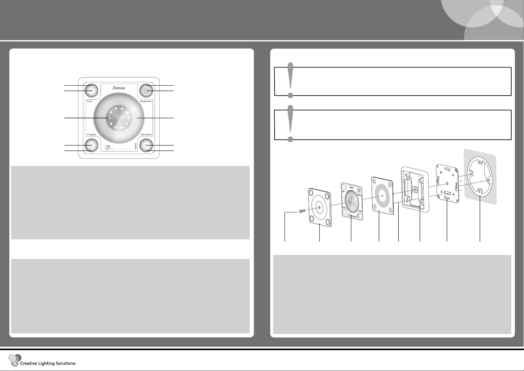
LAY-OUT DESCRIPTION
The Zense is used with the latest Capsense technology. The buttons do not have te be pressed. Just touching
the buttons or slider is enough to control the Zense.
B1
I1
I3
B3
I4
L1-10
B4
B2
I2
S1
The indication LEDs will indicate where the Zense is in it’s menu and what value is selected. The Zense uses
constant and flashing LEDs to indicate several states.
I1 Constant: brightness control.
I2 Constant: colour control, Zense is in colour mode.
I3 Constant: saturation control, when colour mode.
Constant: speed control, when program mode.
Flashing: saturation control, when program mode.
I4 Constant: program control, Zense is in Pogram mode.
L1-10 Constant: circle of LEDs indicate the selected value.
Clear plastic screw Clear plastic front cover Display cover PCB FrameConnector Mounting plate Wall socket
INSTALLATION
ATTENTION!
Don't use the bottom and upper mounting hole to install the CLS Zense!
Only use the left and right mounting holes shown in the drawing. Keep
the connector at the bottom of the CLS Zense!
WARNING
Wall installation
Maximum fixtures on the CLS Zense Amount
• CLS Covelight Superior RGB 150 LEDs 10 metres
• CLS Covelight Superior RGB 300 LEDs 5 metres
• CLS Colourcove X Bright 10 metres
• CLS RGB Quentin LED-pipe, 34,5 cm 18 pipes
• CLS RGB Quentin LED-pipe, 101 cm 6 pipes
• CLS RGB LED-pipe, 34,5 cm 18 pipes
• CLS RGB LED-pipe, 101 cm 6 pipes
• CLS Manon RGB V2-1, 12,5 cm 48 pieces
• CLS Manon RGB V2-2, 26,5 cm 24 pieces
• CLS Manon RGB V2-3, 50,5 cm 12 pieces
ATTENTION!
Before installation, determine exactly how the system needs to be
controlled with the Zense. Is the direct drive system used or DMX or even
both. There are some differences when using direct drive, DMX or both.
WARNING
www.cls-led.com
CLS manuals
CLS Zense
- 5 - - 6 -
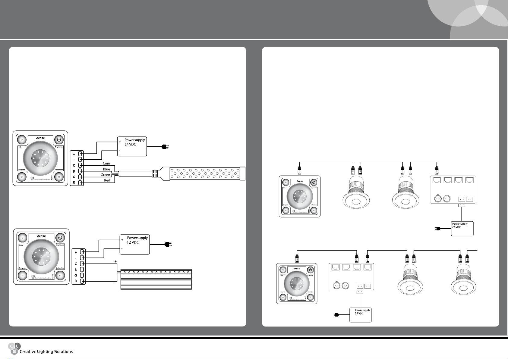
DIRECT DRIVE SYSTEM
The CLS Zense can be used to directly drive voltage controlled LED products. The CLS Zense is fitted with a
6-pole universal connector to make installation of many products possible. The power supply needed for the
voltage-controlled LED product is also used to power the CLS Zense. Therefore, the supplied power supply is
not needed.
Example: The CLS Zense with RGB products (e.g. the CLS Colourcove X Bright).
The RGB fixture works with 24 VDC. The power supply for the RGB fixture is connected to the [+] and [-]
contacts of the CLS Zense. The RGB fixture is connected to the [R], [G], [B] and [C] contacts of the CLS Zense,
as shown in the drawing below.
Example: The CLS Zense with single colour products (e.g. the CLS Safestairs).
The single colour fixture works with 12 VDC. The power supply for the single colour fixture is connected to the
[+] and [-] contacts of the CLS Zense. The single colour fixture is connected to the [R] and [C] contacts of the
CLS Zense.
RGB fixture
CLS Zense
Single colour fixture
CLS Zense
The maximum power that can be driven by the CLS Zense depends on the voltage of the product. A simple
formula can be used to calculate the maximum power: 4A x Voltage product = Power
CLS Zense CLS LON
CAT5 UTP cable max. 15 m
CLS LON connectionbox
1 2 34
DMX power
CLS Zense
CLS LON
CLS LON connectionbox
CAT5 UTP cable max. 15 m
1 2 34
DMX power
With CLS LON connectionbox.
DMX CONTROL SYSTEM
The CLS Zense is able to control light fixtures with DMX. It sends out the colour and brightness settings for a
LED fixture. It can control single colour, RGB, RGBA, RGBW, RGBAW products. It also supports a optional
master channel. A master channel is used by several products to control the brightness separately from the
colour control. This enables brightness control without changing the colour setting. The master channel is
usually located behind or before the colour channels. The Zense supports both ways and can be configured.
The connection of the DMX is according to the CLS standard and also used for the CLS LON. This way the CLS
Zense can be directly connected in the CLS LON system. The CLS Zense is powered from the UTP cable and
sends out the DMX over the same UTP cable. For other applications a splitter block with converter cables are
added to connect the supplied power supply and standard DMX cable to the controller. The CLS Zense can
control multiple fixtures via DMX. All these fixtures should be set to DMX address 1.
Example: The CLS Zense with the CLS LON system.
The CLS Zense can be connected to the last CLS LON or a free output on the CLS LON connection box.
Standard straight CAT5 UTP cabling can be used.
www.cls-led.com
CLS manuals
CLS Zense
- 7 - - 8 -
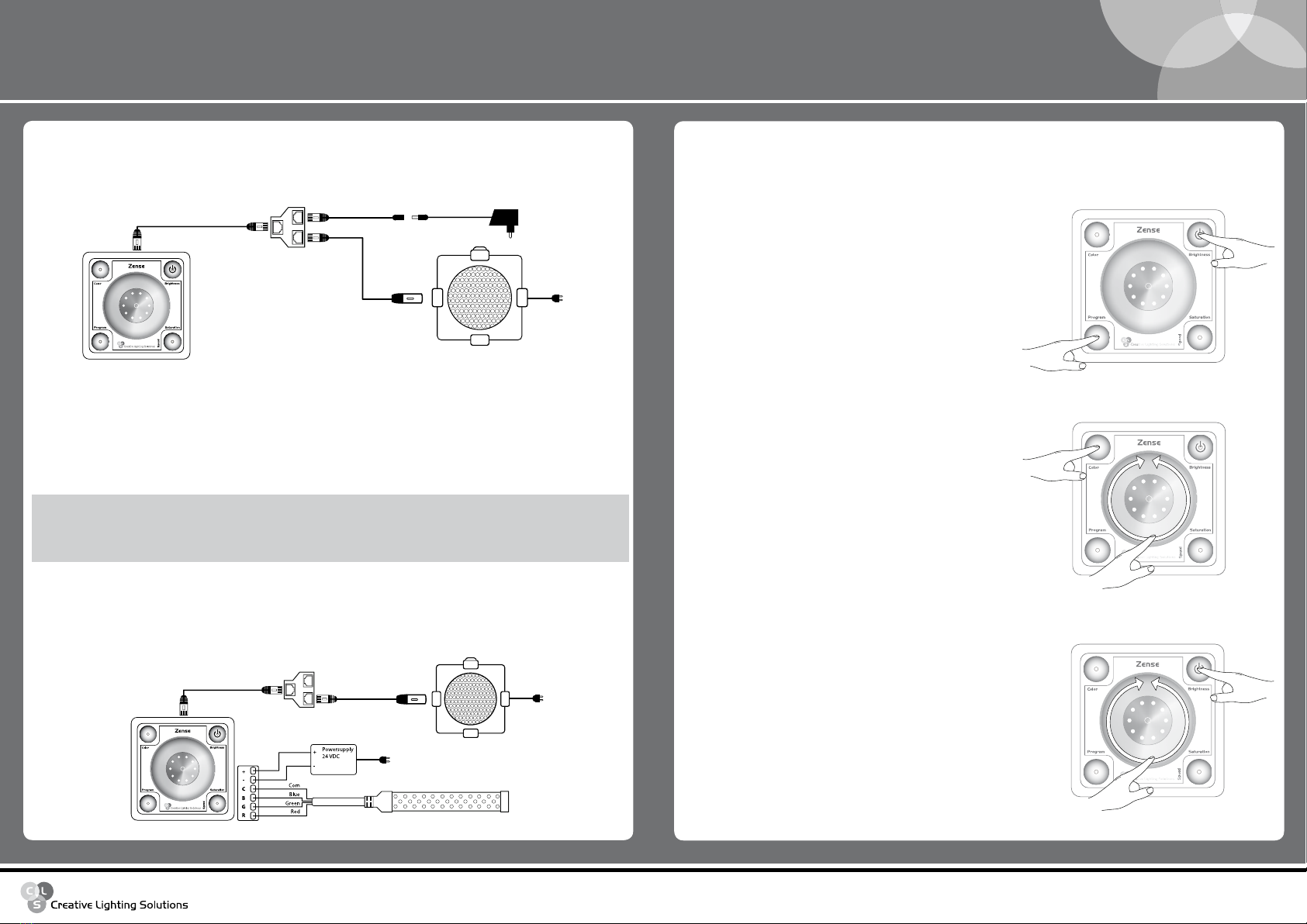
CLS Zense
CAT5 UTP cable max. 15 m RJ45 Splitter
DMX fixture
RJ45 to XLR cable
RGB fixture
CLS Zense
CAT5 UTP cable max. 15 m RJ45 Splitter
DMX fixture
RJ45 to PWR cable
RJ45 to XLR cable
Power supply
Example: The CLS Zense with other DMX fixtures (e.g. the CLS LED PAR RGB).
The CLS Zense can be connected with the supplied connector kit. Standard straight CAT5 UTP cabling can be
used between the splitter and the CLS Zense.
COMBINED SYSTEM
It is also possible to use the DMX and Direct drive together. However, this is only possible for SINGLE colour
(1 channel DMX) and RGB (3 channel or with master 4 channels DMX). The CLS Zense uses the power that is
connected to power the voltage-controlled LED product. The same colour and brightness setting is sent out
via DMX. This makes it possible to control the colour of the RGB fixture and also of the DMX fixture. Be aware
that not all LEDs are exactly the same, it is possible that there is a slight difference in colour.
As described in the table above the direct drive system allows a maximum of three channel control.
• 1 Channel can be used to control single colour LED products. The Zense only uses the brightness control.
• 3 Channels can be used for LED products with RGB.
The colours that are controlled are the same for direct drive as for DMX, however the direct drive can support
only up to 3 channels.
1 Channel 3 Channels 4 Channels 5 Channels Master
Direct control √√
DMX controll √√√√√
CONFIGURATION
After the installation is done the CLS Zense must be configured.
Step 1
To access the configuration mode place your finger on the
Program button while tapping three times on the brightness
button within 3 seconds.
When configuration mode is entered LED [I2] starts flashing
3 x
AB
Step 2
By placing your finger on the colour button you are able to
configure the channels of the CLS Zense. Move your finger
over the slider to adjust the setting.
LED [I2] is flashing
LED L1 on: Single colour (Direct drive and DMX)
LED L1-3 on: RGB (Direct drive and DMX)
LED L1-4 on: RGBA or RGBW (DMX only!)
LED L1-5 on: RGBAW (DMX only!)
3 x
AB
3 x
AB
Step 3
By placing your finger on the Brightness button, you are able to
configure the master channel of the CLS Zense. Move your
finger over the slider to adjust the setting.
LED [I1] is flashing
LED [L1]: Master ch. Off
LED [L2]: Master ch. Behind (master is added behind colour channels)
LED [L3]: Master ch. Before (master is added before colour channels)
The master function only applies for DMX!

www.cls-led.com
CLS manuals
CLS Zense
- 9 - - 10 -
3 x
AB
Colour
Touching the colour button will set the Zense to colour
control. Indication LED I2 is on. The slider can now be used
to scroll through the colour palette. The image of the colour
palette under the slider is equal to the selected colour.
The LEDs L1-L10 give an indication of the selected colour.
OPERATING
Switch ON
The Zense is switched on by touching any button or the slider. The Zense will return where it was turned off.
This way it is not necessary to select your favourite settings every time the Zense is switched on.
Switch OFF
Holding the brightness button for ± 3 seconds will switch off the Zense. The controlled LED products are
switched off. For DMX the all channels are set to zero and the direct drive output is switched off.
Step 4
Save the configuration, place and hold your finger on the
Saturation button (A) until the LEDs stop flashing. The CLS
Zense always returns to Colour control.
Cancel the changes, place and hold your finger on the
Program button (B) until the LEDs stop flashing. The CLS Zense
always returns to Colour control.
The Zense is now configured and ready to be used!
3 x
AB
Brightness
Touching the brightness button will set the Zense to bright-
ness control. Indication LED I1 is on. LED I2 or I4 is still on,
indicating that the Zense is in colour or program mode.
The slider can be used to adjust the brightness.
The LEDs L1-L10 indicate the brightness that is selected on a
scale from 5-100%.
3 x
AB
Program 1: Red Green (Fade)
Program 2: Green Blue (Fade)
Program 3: Blue Red (Fade)
Program 4: Yellow Cyan (Fade)
Program 5: Cyan Magenta (Fade)
Program 6: Magenta Yellow (Fade)
Program 7: Orange Yellow (Fade)
Program 8: Pink Magenta (Fade)
Program 9: Rainbow (red-green-blue) (Fade)
Program 10: Rainbow (red-blue-green) (Fade)
The LEDs L1-L10 indicate which program is selected.
L1 stands for program 1, L2 for program 2 and so on.
Program control
Touching the program button will set the Zense to program control. Indication LED I4 is on. The slider can now
be used to select a program. The Zense is pre-programmed with 10 different colour programmes.
3 x
AB
Saturation
Colour mode: touching the saturation button will set the Zense
to saturation control when the Zense is in colour
mode. LED I3 is on. LED I2 is also on, indicating that
the Zense is in colour mode. Holding the saturation
button for ±3 seconds will set the saturation to 0%.
Program mode: holding the saturation button for ± 3 seconds will
set the Zense to saturation control when the Zense
is in colour mode. LED I3 is flashing. LED I2 is also
on, indicating that the Zense is in colour mode.
Zense configuration Fourth channel 0-100% Fifth channel 0-100% Saturation all channels
1 channel - - -
3 channels - - 0 – 100%
4 channels 0-50% -50-100%
5 channels 0-60% 20 – 80% 80 – 100%
The slider can now be used to adjust the saturation. The LEDs L1-L10 indicate the saturation that is
selected on a scale from 0-100%.
The saturation is also used to control the fourth and fifth channel, if configured. The colour control will
as described in the table below.
www.cls-led.com
CLS manuals
CLS Zense
- 11 - - 12 -
2007 CLS-LED BV. All rights reserved. Information is subject to change without notice. CLS-LED BV and all affiliated companies disclaim liability
for injury, damage direct or indirect loss, consequential or economic loss or any other loss occasioned by the use of, inability to use or reliance
on the information contained in this manual. No part of this manual may be reproduced, in any form or by any means, without permission in
writing from CLS-LED BV. Other legal information can be found in our General conditions to be found on the back of your CLS-LED BV invoice
or on our website www.cls-led.com/conditions.pdf
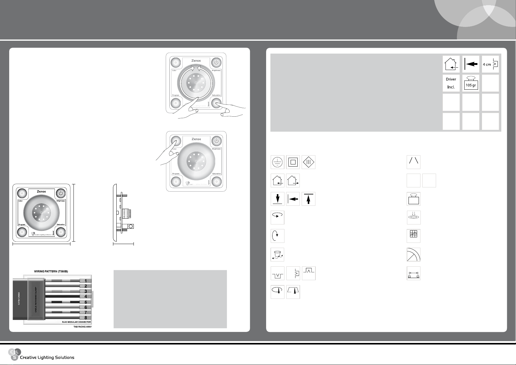
Multiple connection
Possiblities on a fixture
Installation depth
In centimeters
Swivel
Fixture is horizontally rotatable,
indicated in degrees
Swivel
Fixture is vertically rotatable,
indicated in degrees
Mounting hole
In centimeters
Application area
Indoor or outdoor
Application area
Floor, wall or ceiling
Protection class
One, two or three
350º
350°
Cable length
Maximum cable attached
on the fixture in centimeters
Lifespan
Of the light source in hours
Driver
Inclusive or exclusive
Pressure
Maximum pressure on
the fixture per kg/cm2
Weight
In gram/kilogram
Curve
Minimal bending curve
in centimeters
Driver
Incl.
10.000 h
Driver
Excl.
200 cm
6 cm
LED pitch
Pitch between the
LEDs in millimeters
20 mm
15kg/cm2
4x4 cm
4 cm
4 cm
4 cm
4 cm
List of symbols
TECHNICAL SPECIFICATIONS
Input voltage: 12 - 24 VDC
Power consumption: max. 2 Watt
Direct drive current: max. 4 A
Housing: ABS and Polycarbonate
IP value: IP20
Measurements: 82 x 82 x 30 mm (hxwxd)
Weight: 105 gr
Operating ambient temperature: -10 ºC till +40 ºC
MEASUREMENTS
82 mm
82 mm 30 mm
PIN COLOUR FUNCTION
1 Orange/white Not connected
2 Orange Not connected
3 Green/White Not connected
4 Blue DMX data -
5 Blue/White DMX data +
6 Green Not connected
7 Brown/White PWR +
8 Brown PWR - (DMX com)
PINNING DMX OUTPUT
3 x
AB
Speed control
Touching the saturation button will set the Zense to speed control,
if the Zense is in program mode. Indication LED I3 is on. LED I4 is
also on, indicating that the Zense is in program mode. The slider
can now be used to adjust the speed of the programs.
The LEDs L1-L10 indicate the selected speed on a scale from 1 hour
to 10 seconds.
Full white
Holding the colour button for ± 3 seconds will set the saturation
and brightness to 100%. This will set all lights to maximum light
output. This feature can be used when there is a need for high light
output. When button colour or program is touched the Zense will
return to the old setting.
Other Creative Lighting Solutions Dj Equipment manuals

Creative Lighting Solutions
Creative Lighting Solutions CLS RGB LED Par Controller User manual

Creative Lighting Solutions
Creative Lighting Solutions CLS LED PAR56-V3 User manual

Creative Lighting Solutions
Creative Lighting Solutions REVO MODULAR User manual

Creative Lighting Solutions
Creative Lighting Solutions REVO Compact Basic User manual


