CRESTO RESQ RED Pro III User manual

,
EN
SV
NO
DA
FI
DE
IT
FR
ET
PL
ES
TR
PT
CS
NL
简体中文
INSTRUCTIONS FOR USE &
INSPECTION CARD FOR
RESQ RED PRO III

© RESQ RED Pro III 1
FOR YOUR OWN SAFETY, IT IS
IMPORTANT THAT YOU READ
AND FULLY UNDERSTAND
THIS MANUAL!
RESQ RED Pro III
EN
INSTRUCTIONS FOR
USE & INSPECTION CARD
FOR
1 INTRODUCTION 2
2 MARKING & ILLUSTRATIONS 2
3 USING THE RED PRO III 3
4 TECHNICAL DATA 4
5 EQUIPMENT 4
6 OPERATION 4
7 MAINTENANCE AND INSPECTION 6
8 SUSTAINABILITY & RECYCLING 7
9 CE 7
10 INSPECTION- AND USER LOG 7
11 EXPERT USE 8

© RESQ RED Pro III2
This document gives information about the correct use of the RED Pro III in different situations. These instructions must be read
and fully understood by all persons who are going to use the RED Pro III. We also recommend that all employers must read these
instructions carefully, to ensure a good safety level together with a full understanding of the product and its use. Users shall be
trained in the use of the equipment.
1 INTRODUCTION
This emergency equipment is designed for evacuation from height, and operates automatically, descending in a bi-directional
format. It can be used for one or two persons descending at the same time with a controlled descent speed of 0,5-2m/s. It is tted
with an integrated rescue lifting function that can be used to lift one person for short distances, in accordance with the limitations
for load and distances set out under “Technical data” in this user instruction.
User training with the RED Pro III should be under supervision of Cresto trained instructors or Instructors authorized by Cresto or
Cresto partners.
This equipment is made in accordance with the European PPE Regulation 2016/425 and complies with EN341:2011 Descender
device class A & class B; rescue lifting device EN1496:2017.
Applicable as evacuation equipment from Wind turbines, tower cranes, sky lifts, buildings, towers etc.
Warning! The equipment shall only be used by a person trained and competent in a safe use.
Warning! The user-/s must be in good physical and mental condition. In case of known disorder, the user must be aware of pos-
sible consequences, as conditions such as cardiovascular conditions, diabetes, blood pressure deviations, epilepsy and balance
problems or any other medical condition that can be hazardous to the safety using the equipment.
Warning! Equipment use must be supported by the company’s own accident emergency procedures related to daily work.
Warning! Do not make any alternations or additions to the equipment without the manufacturer´s prior written consent, and any
repair shall only be carried out in accordance with the manufacturer´s procedures and guidelines.
Warning! Do not use the equipment outside its limitations or for no purpose other than that which it is intended.
Warning! The equipment must only be used for rescue and evacuation and not intended as fall arrest equipment or as a utility
crane.
2 MARKING & ILLUSTRATIONS
See gure 1 and gure 2.
1. Manufacturer
2. Compliance
3. Serial number
4. Date of manufacture
5. Weight restrictions
6. Temperature limit
7. User instruction
8. Length
8
3
4
5
1
7
6
2
Figure 1

© RESQ RED Pro III 3
Note! Make sure that the product label is legible or that the RFID is readable.
3 USING THE RED PRO III
Note! Before use of the equipment always check the function and condition to ensure safe usage. If stored in the Cresto vacuum
solution, only check that the vacuum is still intact. If punctured you must inspect the function and condition of the equipment before
use.
Check the rope along its entire length for any signs of chang, varying thickness, cuts, chemical especially acids contact, change
of shape, UV-deterioration, stiffness or other deformation with permanent kinks. Check the stitches in the end terminations for any
loose threads or damage. Check the carabiners in the rope and equipment for any signs of signicant corrosion, wear, deformation,
cracks and limited gate function. Check the descender device for any cracks, deformation or missing parts. While pulling the rope
thru the device, check for any ”wobble” in the handwheel. Test the brake function of the device by pulling the rope through the
device hard for at least 3m in each direction (Note: that the brake force must increase with increased pulling power). Check the
friction loop for any deformation. Check the function and spring action of the rope locking mechanism.
Warning! Withdraw the device immediately until conrmed in writing by a competent person if any doubts arises about its condition
for safe use or if it has arrested a fall.
Warning! Always use a fall arrest system if there is a risk for fall when rigging the equipment.
Warning! Always ensure that in a fall-arrest system, it is essential to check for clearance below the user before each use, to avoid
any impact with the ground or an obstacle in case of a fall. Make sure that the anchor point is correctly positioned, in order to limit
the risk and the height of fall. When using multiple pieces of equipment together, a dangerous situation can arise if the safety
function of one piece of equipment is affected by the safety function of another piece of equipment.
Warning! Extreme temperatures may affect the capacity of the device.
Warning! Protect the rope for any edges that may compromise its integrity.
Warning! Long descent distance with minimum load in high wind and trailing rope may affect the descent speed as the trailing
rope will create a counter force.
Warning! Always have an operator operating the device when top mounted if entangelment of the rope will occur and block the
descent. Last person-/s evacuating will have to body mount the equipment to remain in control.
Warning! The RED Pro III is equipped with a Torque limiter in the handwheel that limits the lifting force to approx. 170kg. This
could affect lifting operations when lifting over edges due to increased friction between casualty and device.
Warning! During descent the handwheel will spin fast and may cause burn injuries.
Note! Always position the device so that the handwheel doesn’t come in contact with any structure as this can slow down the
descent or result in a complete stop.
Compatible with PPE components within EN, ANSI or CSA designed for the purpose.
Note! This must always be in conjunction with the national and local requirements.
Only connect to a structure with a minimum strength of 12kN or designed for the purpose. Strive to position as high above as
possible and protect from edges that could damage the rope.
To be used with fall arrest harness EN361, Rescue harness EN1497 or rescue slings EN1498.
See user instruction of the body holding device for correct attachment of the equipment.
Figure 2

© RESQ RED Pro III4
4 TECHNICAL DATA
Type RED Pro III
Rope Kernmantel rope 9,6mm EN 1891:1998 A Material: Polyamide/Polyamide; Elongation: 4%;
Cover 40%; Weight: 61g/m
Certication EN341:2011 cl.A & cl.B (cl.A 100kg, cl.B 200kg),
EN1496:2017 cl.B
Compliance ANSI/ASSE Z359.4-2013
CAN/CSA Z259.2.3:16
Max descent height 160 m
Max descent load 200 kg
Min. descent load 50 kg
Max. ambient temperature +60°C
Min. ambient temperature -40°C
Max. lifting capacity 136 kg
Max. lifting height 12 m
Max. height/load descending 48 x 160m with max. load 100kg
5 x 160m with max. load 200kg
Descent velocity 0,8m/s loads up to 100kg. Increasing speed when load is increased, max. speed of 2m/s
Calculation of descend energy W= m * g * h * n
m= descent load (kg), g= 9,81 m/s2, h= descent distance (m), n= number of descents
Class A: W=7,5 x 10 6J; Class B: 1,5 x 10 6J
5 EQUIPMENT
See gure 3.
9. Carabiner device
10. Friction loop
11. Rope clamp
12. Handwheel
13. Carabiner rope
14. Trailing rope
15. Rescue rope
16. Accessories (Optional)
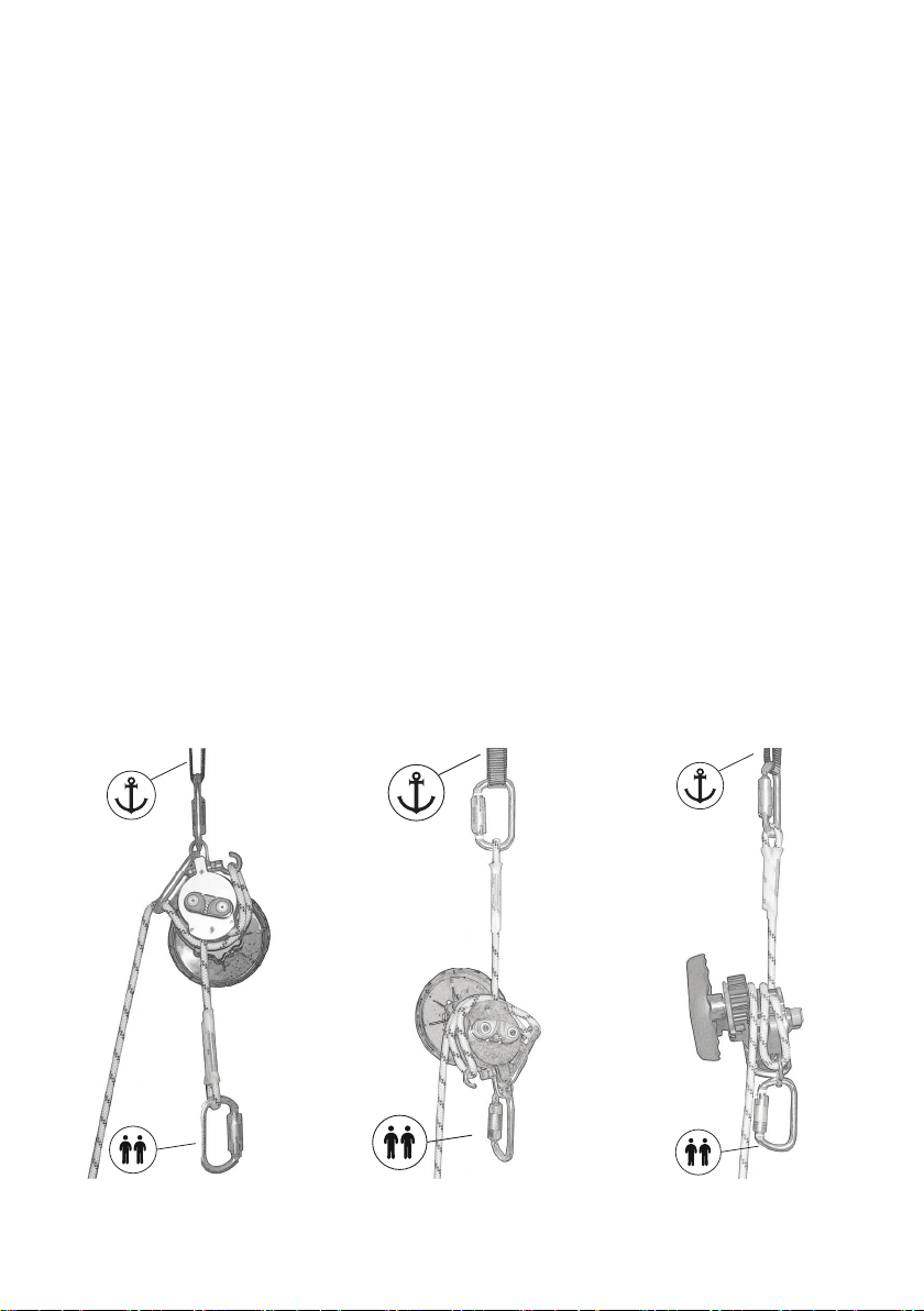
6 OPERATION
6.1. BASIC EVACUATION -
GENERAL INFORMATION
Secure the equipment to the anchor point at least one meter above the
platform. Check that the intended descent path is free of any obstacle
that may obstruct the descent.
Throw the rope bag to the ground if this is appropriate and done
responsibly. Alternatively, the bag can travel with the rst evacuee or be
left at the exit level*.
Note! The last evacuee MUST descend with the device (body mounted)
and carry the rope bag, if the bag hasn´t already been dropped to the
ground).
1
2
3
4
5
6
7
8
Figure 3

© RESQ RED Pro III 5
Note! If not necessary, do not stop the descent until you have reached the ground to
minimize the risk of having the rope come into contact with any hot surfaces of the
device.
6.2. BASIC EVACUATION - TOP MOUNTED
1. Attach the rescue rope carabiner to the harness attachment point (marked with
A) or approved body holding device in accordance with its user instruction.
Remove any slack between you and the device by pulling the trailing rope
downwards. Hold on to the trailing rope while transferring the load into the
device. Carefully swing free of the platform and ease the grip around the
trailing rope to begin the descent.
Note! Always keep control/grip around the trailing rope as it might be impossible to regain control if lost.
Warning! The body of the device will accumulate heat from the brake and may be HOT enough to damage the rope if not adminis-
trated correctly. Always use protective gloves when operating the device and rope.
2. Once the rst person-/s have reached the ground and disconnected from the equipment, the next person may hook onto the
trailing rope (which subsequently becomes the rescue rope) using the carabiner at the end (or making a gure of 8 knot, see
gure 4, if the equipment length is not site specic depending on rope length and descent height).
Warning! If a gure of 8 knot is used instead of the end carabiner always ensure that it is place on the correct end, if wrongfully
placed the descent may be blocked by the knot. Always pull through an extra meter or two on the former rescue rope to ensure
room for the knot to ensure that next evacuee reaches the ground.The lowering process described with continuous lowering of
several evacuees one after the other is called “shuttling”. When evacuating a lot of persons ensure that this complies with the
maximum descent and load according to the specication under technical data.
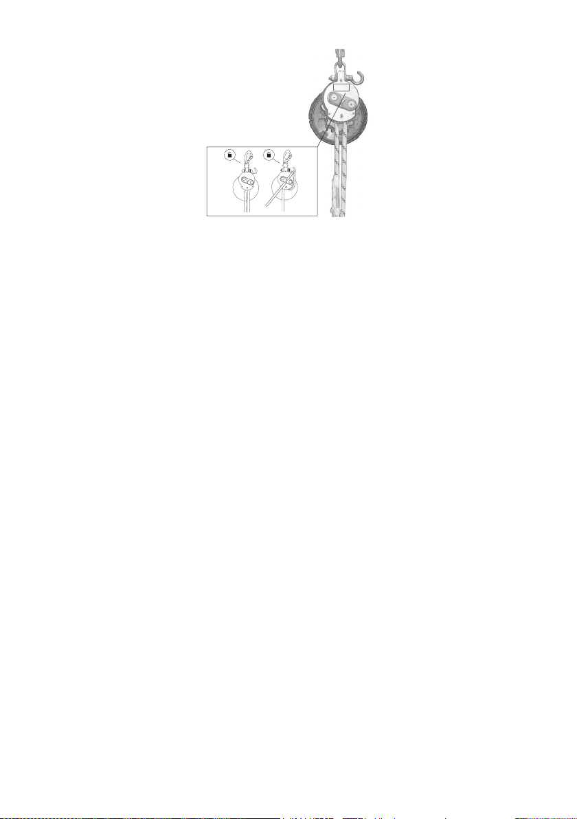
6.3. BASIC EVACUATION - BODY MOUNTED
See gure 5.
1. Attach the rescue rope carabiner to the anchor point. Attach the device carabiner to the harness attachment point (marked with
A) or approved body holding device in accordance with its user instruction. Remove any slack between you and the device by
pulling the trailing rope upwards. Hold on to the trailing rope, see gure 6, while transferring the load into the device. Carefully
swing free of the platform and ease the grip around the trailing rope to begin the descent.
Note! If possible try to position the device so that the handwheel faces away from the user-/s to minimize risk of injuries.
2. To decrease or manually control the descent speed e.g. in narrow spaces, add friction by passing the rope thru the friction loop
on the device. For Body mounted device, see chapter 11. Expert use.
Figure 4
Figure 5 Figure 6 Figure 7

© RESQ RED Pro III6
6.4. BASIC LIFTING
See gure 7.
1. Attach the equipment to an anchor point directly via the device carabiner or with a anchor sling at least 1 meter above the
casualty.
2. Pull out the rescue rope so you can attach it to the casualty’s harness (upper attachment point).
3. Remove any slack between you and the device by pulling the trailing rope downwards.
4. Pull the trailing rope through the friction loop and insert the rope into the rope clamp and tighten.
5. Start to lift by turning the handwheel in counterclockwise direction with two hands. Frequently tighten the slack between the
friction loop and rope clamp. Approx. after every 5 turns on the handwheel.
Note! Secure if necessary the trailing rope around the device to eliminate the risk of unintentional descent.
6. Free the casualty from its fall arrest
7. Start the control descent by releasing the trailing rope from the rope clamp by pulling it outwards.
Warning! Never let go of the trailing rope as it could be difcult to regain control if lost.
Note! Always verify lifting progress by looking at the rope colour threads movement in and out of the device.
7 MAINTENANCE AND INSPECTION
The rescue and evacuation equipment is an emergency equipment and must be inspected after it has been unpacked and used.
The equipment must be service and repacked by a Cresto authorized competent person.
Note! During transport and storage, keep the device dark and dry.
Inspection and service of the equipment must be carried out by the manufacturer or a partner whom is authorized by the
manufacturer and in accordance with the manufacturers guidelines.
If stored, maintained as described and used in normal condition, the expected lifespan of this device is 4-6 Years. 10 Years in
ResQ vacuum pack. The equipment is serviceable up to 20 Years.
Note! If the equipment is installed at a workstation and left in place between inspections it must be protected by the Cresto vacuum
solution to ensure protection from environmental conditions.
Note! The device shall be stored in a dry, dark and well-ventilated location, protected against steam, sharp edges, vibration and
UV-light. The device shall be kept clean for best functionality and durability. Metal parts can be blown clean with compressed air.
Avoid lubricating oil! Lightly soiled devices can be washed with a brush in lukewarm water. A mild soap solution can be used. Wet
devices is hung up to dry. The device shall be allowed to air-dry without being subjected to open re or any other heat source.
Figure 8 Figure 9

© RESQ RED Pro III 7
The device log on the last page must be updated with all periodic inspections, service and repairs and other matters concerning
the safe use of the device, if the CRESTO INSPECTOR data base is not utilized.
Warning! For the user’s safety the device shall be inspected at least every twelfth month in order to ensure its functionality and
durability (refer to EN 365). The inspection can be registered in Inspector online at www.cresto.se
Note! In cases of frequent usage of the device or in aggressive environments, inspections shall be carried out at shorter intervals
(as decided by a trained competent person).
Warning! The inspection shall be carried out by a competent person (a person who has been trained and is competent in fall
protection equipment inspection) who holds a certicate for inspection and in accordance with the manufacturer’s inspection
procedure as well as EN 365.
Warning! The device must not be modied or supplemented using accessories other than those supplied by the manufacturer.
Repairs or replacement of parts may only be carried out by the manufacturer.
Warning! Do not make any alterations or additions to the equipment without the manufacturer’s prior written consent, and any
repair shall only be carried out in accordance with manufacturer’s procedures.
8 SUSTAINABILITY & RECYCLING
We design and manufacture premium products, with premium materials, to be used actively and to last long. When the product is
decided to be taken out of use, or its maximum lifetime has expired, it should be recycled according to your local legislations. Our
products are made of polyester, polyamide or PVC and metal components. If necessary dismantle the metal components before
recycling. You can also send the complete product to Cresto and we will take care of the recycling in order to reduce our impact on
the environment.
9 CE
Manufacturer and expert:
CRESTO AB
Lägatan 3
SE-302 60, Halmstad, Sweden
T: +46 (0) 35 710 75 00
cresto.com
Type certication and approval is carried out by: Production control by:
Warning! It is essential for the safety of the user that if the product is re-sold outside the original country of destination the reseller
shall provide instructions for use, for maintenance, for periodic examination and for repair in the language of the country in which
the product is to be used.
Download your User instruction and Declaration of conformity on http://www.cresto.com/documentation
10 INSPECTION- AND USER LOG
Company: Product: Descender device, class A and B
User: Reference:
Marking: CE 0158 Length:
Date of Purchase: Serial Number:
Date of
manufacturing:
Date rst put into
use:
Notied Body: 0158
DEKRA Testing and Certication
Dinnendahlstr. 9
44809 Bochum
Germany
Notied Body: 0158
DEKRA Testing and Certication
Dinnendahlstr. 9
44809 Bochum
Germany

© RESQ RED Pro III8
Inspection and logged issues
11 EXPERT USE
This section is not part of the EU type certication tests and is tested veried by the manufacturer
to ensure correct and safe use.
11.1. ADDITIONAL FRICTION - BODY MOUNTED DESCENT
See gure 10.
Note! This operation requires an additional carabiner.
1. Connect the additional carabiner around the rescue rope just above the device.
2. Pull the trailing rope thru the friction loop and insert it into the carabiner. Make sure that the trailing
rope is managed so no entanglement occurs.
3. Start the descent by easing the grip around the trailing rope. Make sure that the trailing rope is not lost
during descent.
11.2. 280KG DESCENT WITH RED PRO III
Note! Descending with exceeded load over 200kg requires additional friction and is limited to ONE
descent of maximum 160m.
11.3. 280KG DESCENT WITH TOP MOUNTED RED PRO III
See gure 11.
1. Attach the device to the anchor point directly or with the anchor sling EN795 cl B around a
sufcient structure. Figure 10
Date
NameandSignature
ofthecompetentperson
Nextduedatefor
periodicexamination
© RESQ RED Pro III 9
Figure 11 Figure 12A Figure 12B
2. Connect an additional carabiner to the device top anchorage
3. Pull the trailing rope through the friction loop and around the device housing. Insert the trailing rope into the carabiner. Make
sure that the trailing rope is managed so no entangelment occurs.
4. Connect the rescue rope to the harness attachment point of person 1 and use an additional carabiner between the rescue rope
carabiner to the harness attachment point of person 2.
5. Remove any slack between the persons and the device.
6. Hold rmly the trailing rope until the persons load is transferred to the device.
Note! This conguration requires that you have an operator operating the descent next to the equipment. See following chapter for
body mounted conguration.
7. Start the descent by easing the grip around the trailing rope.
11.4. 280KG DESCENT WITH BODY MOUNTED RED PRO III
See gure 12A and gure 12B.
1. Attach the rescue rope to the anchor point directly or with the anchor sling EN795 cl B around a sufcient structure.
2. Connect an additional carabiner to the device top anchorage.
3. Pull the trailing rope through the friction loop and around the device housing. Insert the trailing rope into the carabiner. Make
sure that the trailing rope is managed so no entangelment occurs.
4. Connect the device to the harness attachment point of person 1 and use an additional carabiner between the device carabiner
to the harness attachment point of person 2.
5. Remove any slack between the persons and the device.
6. Hold rmly the trailing rope until the load is transferred to the device.
Warning! Make sure that any fall arrest systems are disconnected prior to the start of descending as lifting with two persons will
overload and could damaged the equipment.


© RESQ RED Pro III 1
FÖR DIN EGEN SÄKERHET ÄR DET
VIKTIGT ATT DU LÄSER IGENOM
OCH FÖRSTÅR INNEHÅLLET
I DENNA BRUKSANVISNING!
RESQ RED Pro III
SV
INSTRUKTIONER FÖR ANVÄNDNING
OCH BESIKTNINGSKORT
FÖR
1 INLEDNING 2
2 MÄRKNING OCH ILLUSTRATIONER 2
3 ANVÄNDA RED PRO III 3
4 TEKNISKA DATA 4
5 UTRUSTNING 4
6 ANVÄNDNING 4
7 UNDERHÅLL OCH INSPEKTION 6
8 HÅLLBARHET OCH ÅTERVINNING 7
9 CE 7
10 KONTROLL- OCH ANVÄNDNINGSLOGG 7
11 EXPERTANVÄNDNING. 8

© RESQ RED Pro III2
Det här dokumentet innehåller information om hur RED Pro III används i olika situationer. Alla som kommer att använda
RED Pro III måste läsa igenom och förstå dessa anvisningar i sin helhet. Vi rekommenderar också att alla medarbetare läser
igenom anvisningarna noggrant så att en bra säkerhetsnivå kan garanteras tillsammans med en full förståelse för produkten och
dess användning. Alla användare ska utbildas i hur utrustningen används.
1 INLEDNING
Denna nödutrustning är konstruerad för evakuering från höjd och fungerar automatiskt för nedstigning i ett dubbelriktat format.
Den kan användas för nedrning av en eller två personer samtidigt med en kontrollerad nedstigningshastighet på 0,5–2 m/s. Den
är utrustad med en integrerad räddningslyftfunktion som kan användas för att lyfta en person korta sträckor, i enlighet med de
begränsningar för belastning och avstånd som anges under ”Tekniska data” i denna bruksanvisning.
Utbildning i hur man använder RED Pro III bör ske under överinseende av instruktörer som har utbildats eller godkänts av Cresto
eller Crestos samarbetspartners.
Denna utrustning är tillverkad i enlighet med den europeiska PPE-förordningen 2016/425 och uppfyller kraven enligt
SS-EN341:2011 Nedrningsdon klass A och klass B; Lyftanordning för räddning SS-EN1496:2017.
Gäller som evakueringsutrustning från vindkraftverk, tornkranar, lyftkranar, torn osv.
Varning! Utrustningen får endast användas av en person som är utbildad och behörig för säker användning.
Varning! Användaren måste vara i god fysisk och mental form. Om användaren har ett bekräftat sjukdomstillstånd måste denne
vara medveten om möjliga konsekvenser, eftersom till exempel hjärtproblem, diabetes, högt eller lågt blodtryck, epilepsi, balans-
problem eller något annat medicinskt tillstånd som kan äventyra säkerheten när utrustningen används.
Varning! Användningen av utrustningen måste stödjas av företagets egna rutiner vid arbetsplatsolyckor.
Varning! Gör inga ändringar av eller tillägg till utrustningen utan föregående skriftligt medgivande från tillverkaren, och eventuella
reparationer får endast utföras i enlighet med tillverkarens förfaranden och riktlinjer.
Varning! Använd inte utrustningen utanför dess begränsningar eller för något annat ändamål än det som den är avsedd för.
Varning! Utrustningen får endast användas för räddning och evakuering och är inte avsedd att användas som fallskyddsutrustning
eller som en verktygskran.
2 MÄRKNING OCH ILLUSTRATIONER
Se gur 1 och gur 2
1. Tillverkare
2. Överensstämmelse
3. Serienummer
4. Tillverkningsdatum
5. Viktbegränsning
6. Temperaturgräns
7. Bruksanvisning
8. Längd
8
3
4
5
1
7
6
2
Bild 1
© RESQ RED Pro III 3
Obs! Kontrollera att produktetiketten är läsbar eller att RFID-tekniken är läsbar.
3 ANVÄNDA RED PRO III
Obs! Före användning av utrustningen ska dess funktion och skick alltid kontrolleras för att säkerställa säker användning. Om
utrustningen lagras i Crestos vakuumlösning räcker det att kontrollera att vakuumet fortfarande är intakt. Om vakuumlösningen
skulle ha punkterats, ska utrustningens funktion och skick kontrolleras före användning.
Kontrollera repet i hela dess längd för eventuella tecken på nötning, varierande tjocklek, snitt, kontakt med kemikalier – i synnerhet
syror, ändrad form, försämring till föjd av exponering för UV-strålning, stelhet eller andra deformeringar med permanenta halvknutar.
Kontrollera stygnen i repändarna med avseende på lösa trådar eller skador. Kontrollera karbinhakarna i repet och utrustningen för
tecken på betydande korrosion, slitage, deformering, sprickor och begränsad spärrfunktion. Kontrollera nedrningsbromsen med
avseende på sprickor, deformering eller saknade delar. Var observant på eventuella ”wobblande rörelser” hos handratten när du
drar repet genom enheten. Testa enhetens bromsfunktion genom att dra repet genom enheten hårt minst 3 m i vardera riktningen
(Obs: bromskraften måste öka med ökad dragkraft). Kontrollera friktionsslingan med avseende på deformering. Kontrollera funktionen
och fjäderfunktionen hos replåsmekanismen.
Varning! Sluta omedelbart att använda enheten tills en behörig person skriftligen på om det är säkert att använda enheten eller om
den har dämpat ett fall.
Varning! Använd alltid ett fallskyddssystem om det nns en risk för fall vid riggning av utrustningen.
Varning! I ett fallskyddssystem är det viktigt att alltid säkerställa ett fritt fallutrymme under användaren före och efter användning
för att undvika att användaren slår i marken eller ett hinder i händelse av ett fall. Kontrollera att förankringspunkten är korrekt
placerad för att begränsa risken och fallhöjden. Vid användning av era utrustningsdelar tillsammans kan det uppstå en farlig
situation om säkerhetsfunktionen på en del av utrustningen påverkas av säkerhetsfunktionen hos en annan utrustningsdel.
Varning! Extrema temperaturer kan påverkan enhetens kapacitet.
Varning! Skydda repet mot eventuella kanter som kan äventyra dess integritet.
Varning! Lång nedstigningssträcka med minimal belastning vid stark vind och nedrningsrep påverkar nedstigningshastigheten
eftersom nedrningsrepet kommer att skapa en motkraft.
Varning! Se till att alltid ha en operatör som hanterar enheten när denna är toppmonterad om repet skulle sno sig och blockera
nedstigningen. Den person/de personer som evakueras sist måste montera utrustningen på kroppen för att behålla kontrollen.
Varning! RED Pro III är utrustad med en momentbegränsare i handratten som begränsar lyftkraften till cirka 170 kg. Detta kan
påverka lyftoperationer vid lyft över kanter på grund av den ökade friktionen mellan den nödställde och enheten.
Varning! Vid nedstigning kommer handratten att snurra snabbt och kan orsaka brännskador.
Obs! Placera alltid enheten så att handratten inte kommer i kontakt med någon struktur eftersom detta kan bromsa upp nedstig-
ningen eller göra att det helt tar stopp.
Kompatibel med PPE-komponenter i EN, ANSI eller CSA avsedda för ändamålet.
Obs! Detta måste alltid ske i samband med de nationella och lokala kraven.
Anslut endast till en struktur med en minsta hållfasthet på 12 kN eller som är avsedd för ändamålet. Sträva efter att placera enheten
så högt ovanför som möjligt och skydda mot kanter som kan skada repet.
För användning tillsammans med fallskyddssele EN361, räddningssele EN1497 eller räddningsslingor EN1498.
Se bruksanvisningen för selen för korrekt fastsättning av utrustningen.
Bild 2

© RESQ RED Pro III4
4 TEKNISKA DATA
Typ RED Pro III
Lina Kärnmantelrep 9,6 mm SS-EN 1891:1998 A Material Polyamid/Polyamid; Förlängning: 4 %,
Hölje 40 %; Vikt: 61g/m
Certiering SS-EN341:2011 kl.A och kl.B (kl.A 100 kg, kl.B 200 kg),
SS-EN1496:2017 kl.B
Överensstämmelse ANSI/ASSE Z359.4-2013
CAN/CSA Z259.2.3:16
Max. nedstigningshöjd 160 m
Max. nedstigningsbelastning 200 kg
Min. nedstigningsbelastning 50 kg
Max. omgivningstemperatur +60 °C
Min. omgivningstemperatur -40 °C
Max. lyftkapacitet 136 kg
Max. lyfthöjd 12 m
Max. höjd/belastning nedstig-
ning
48 x 160 m med max.belastning 100 kg
5 x 160 m med max. belastning 200 kg
Nedstigningshastighet 0,8 m/s belastningar upp till 100 kg. Hastigheten ökar när belastningen ökar,
maxhastighet på 2 m/s
Beräkning av nedstigningsenergi V= m * g * h * n
m= belastning vid nedstigning (kg), g= 9,81 m/s2, h= nedstigningssträcka (m),
n= antal nedstigningar
Klass A: W=7,5 x 10 6 J; Klass B: 1,5 x 10 6J
5 UTRUSTNING
Se bild 3.
1. Karbinhake
2. Friktionsslinga
3. Repklämma
4. Handratt
5. Karbinhake rep
6. Nedrningsrep
7. Räddningsrep
8. Tillbehör (tillval)
6 ANVÄNDNING
6.1. GRUNDLÄGGANDE EVAKUERING –
ALLMÄN INFORMATION
Fäst utrustningen i ankarpunkten minst en meter ovanför plattformen.
Kontrollera att den tänkta nedstigningsbanan är fri från hinder som kan
hindra nedstigningen.
Kasta ner repväskan på marken om detta är lämpligt och kan göras på
ett ansvarsfullt sätt. Alternativt kan väskan följa med den första personen
som evakueras ned eller lämnas kvar på utgångsnivån*.
Obs! Den sista personen som evakueras MÅSTE ra ner sig med
enheten (kroppsmonterad) och bära repväskan om väskan inte redan
har släppts ner på marken).
1
2
3
4
5
6
7
8
Bild 3

© RESQ RED Pro III 5
Obs! Om det inte är nödvändigt ska nedstigningen inte stoppas förrän du har nått
marken för att minimera risken för att repet kommer i kontakt med heta ytor på
enheten.
6.2. GRUNDLÄGGANDE EVAKUERING – TOPPMONTERAD
1. Fäst karbinhaken på räddningsrepet i fästpunkten på selen (märkt med A)
eller godkänd sele i enlighet med bruksanvisningen. Eliminera eventuellt slack
mellan dig själv och enheten genom att dra nedrningsrepet nedåt. Håll i
nedrningsrepet samtidigt som du överför belastningen till enheten. Svinga
dig försiktigt ut från plattformen och lätta på greppet runt nedrningsrepet för
att påbörja nedstigningen.
Obs! Ha alltid kontroll/behåll hela tiden greppet runt nedrningsrepet eftersom det kan bli omöjligt att återfå kontrollen om du väl
har släppt det.
Varning! Själva enheten ackumulerar värme från bromsen och kan vara tillräckligt VARM för att skada repet om den inte hanteras
korrekt. Använd alltid skyddshandskar när du använder enheten och repet.
2. När den/de första personen/personerna är nere på marken och har kopplats loss från utrustningen kan nästa person kroka fast
sig på nedrningsrepet (som då blir räddningsrepet) med hjälp av karbinhaken i änden (eller gör en överhandsknop i åtta, se
bild 4, om utrustningens längd inte specikt anpassad för platsen beroende på repets längd och nedstigningshöjden).
Varning! Om en överhandsknop i åtta används istället för karbinhaken i änden på nedrningsrepet, måste man alltid se till att knopen
görs på rätt ände då knuten, för om den placeras på fel ställe kan den omöjliggöra fortsatt nedstigning. Dra alltid igen en extra
meter eller två på det tidigare räddningsrepet så att det nns plats för knuten för att säkerställa att nästa person som evakueras
når marken. Nedrningsprocessen som beskrivs med kontinuerlig nedrning av era personer som evakueras efter varandra kallas
”shuttling”. Vid evakuering av många personer, se till att detta överensstämmer med den maximala nedstigningen och belastningen
enligt specikationen under Tekniska data.
6.3. GRUNDLÄGGANDE EVAKUERING – KROPPSMONTERAD
Se bild 5.
1. Fäst karbinhaken på räddningsrepet i förankringspunkten. Fäst karbinhaken på enheten i fästpunkten på selen (märkt med A)
eller godkänd sele i enlighet med bruksanvisningen. Ta bort eventuellt slack mellan dig och enheten genom att dra nedrnings-
repet uppåt. Håll i nedrningsrepet, se bild 6, samtidigt som du överför belastningen till enheten. Svinga dig försiktigt ut från
plattformen och lätta på greppet runt nedrningsrepet för att påbörja nedstigningen.
Obs! Om möjligt, försök att placera enheten så att handratten är vänd bort från användaren/användarna för att minimera risken för
skador.
2. För att minska eller manuellt styra nedstigningshastigheten, t.ex. i trånga utrymmen, kan du öka friktionen genom att dra repet
genom friktionsslingan på enheten. För kroppsmonterad enhet, se kapitel 11. Expertanvändning.
Bild 4
Bild 5 Bild 6 Bild 7

© RESQ RED Pro III6
6.4. GRUNDLÄGGANDE LYFT
Se bild 7.
1. Fäst utrustningen direkt i en förankringspunkt via karbinhaken på enheten eller med en förankringsslinga minst en 1 meter
ovanför den nödställde.
2. Dra ut räddningsrepet så att du kan fästa det i den nödställdes sele (övre fästpunkten).
3. Eliminera eventuellt slack mellan dig själv och enheten genom att dra nedrningsrepet nedåt.
4. Dra nedrningsrepet genom friktionsslingan och för in repet genom repklämman och dra åt.
5. Starta genom att vrida handratten moturs med båda händerna. Korta ofta slacket mellan friktionsslingan och repklämman.
Efter cirka vart femte varv med handratten.
Obs! Säkra vid behov nedrningsrepet runt enheten för att eliminera risken för oavsiktlig nedstigning.
6. Koppla loss den drabbade från dennes fallskydd
7. Starta den kontrollerade nedstigningen genom att frigöra nedrningsrepet från repklämman genom att dra det utåt.
Varning! Släpp aldrig taget om nedrningsrepet eftersom det kan vara svårt att återfå kontrollen om du skulle förlora den.
Obs! Kontrollera alltid lyftförloppet genom att titta på repets färgade trådar när de löper in i och ut ur enheten.
7 UNDERHÅLL OCH INSPEKTION
Räddnings- och evakueringsutrustningen är en nödutrustning och måste besiktigas efter att den har packats upp och använts.
Utrustningen måste servas och packas om av en behörig person som har auktoriserats av Cresto.
Obs! Förvara och transportera enheten mörkt och torrt.
Besiktning och service av utrustningen måste utföras av tillverkaren eller en samarbetspartner som är auktoriserad av tillverkaren
och i enlighet med tillverkarens riktlinjer.
Om utrustningen förvaras, underhålls enligt beskrivningen och används under normala förhållanden är den förväntade livslängden
för denna enhet 4–6 år. 10 år i ResQ vakuumförpackning. Utrustningen kan servas upp till 20 år.
Obs! Om utrustningen installeras på en arbetsplats och lämnas kvar mellan besiktningarna, måste den skyddas av Crestos
vakuumlösning för att säkerställa skydd mot miljöförhållanden.
Obs! Enheten ska förvaras på en torr, mörk och väl ventilerad plats samt skyddas mot ånga, vassa kanter, vibrationer och
UV-strålning. Enheten ska hållas ren för optimal funktion och längsta möjliga produktlivslängd. Metalldelar kan blåsas rena med
tryckluft. Undvik att använda smörjolja! Lätt smutsade enheter kan tvättas med en borste i ljummet vatten. Det går bra att använda
en mild tvållösning. Våta enheter ska hängas upp på tork. Enheten ska lufttorkas utan att utsättas för värmestrålning från öppen
eld eller någon annan värmekälla.
Bild 8 Bild 9

© RESQ RED Pro III 7
Enhetsloggen på sista sidan ska uppdateras vid varje periodisk kontroll, underhåll och reparation och varje annat förhållande som
berör säker användning av enheten, om inte databasen CRESTO INSPECTOR används.
Varning! För användarens säkerhet ska enheten besiktigas minst var tolfte månad för att säkerställa dess funktion och hållbarhet
(se SS-EN 365). Besiktningen kan registreras i Inspector online på www.cresto.se
Obs! Vid frekvent användning av enheten i aggressiva miljöer ska besiktningarna göras med kortare intervall (hur lång tid det ska
vara mellan besiktningarna beslutas av en behörig person).
Varning! Besiktningen ska utföras av en behörig person (någon som är utbildad i och behörig inom besiktning av fallskydds-
utrustning) med certikat för besiktning och i enlighet med tillverkarens besiktningsförfarande samt SS-EN 365.
Varning! Enheten får inte modieras eller kompletteras med andra tillbehör än de som tillhandahålls av tillverkaren. Reparationer
eller byte av delar får endast utföras av tillverkaren.
Varning! Gör inga ändringar av eller tillägg till utrustningen utan föregående skriftligt medgivande från tillverkaren, och eventuella
reparationer får endast utföras i enlighet med tillverkarens förfaranden.
8 HÅLLBARHET OCH ÅTERVINNING
Vi designar och tillverkar premiumprodukter av premiummaterial som är gjorda för aktiv användning och för att hålla länge. När
beslut tas om att ta produkten ur bruk eller om den är uttjänt bör den återvinnas enligt din lokala lagstiftning. Våra produkter är
tillverkade av polyester, polyamid eller PVC och metallkomponenter. Demontera vid behov metallkomponenterna före återvinning.
Du kan också skicka in hela produkten till Cresto så återvinner vi den åt dig för att minska vår miljöpåverkan.
9 CE
Tillverkare och sakkunnig:
CRESTO AB
Lägatan 3
SE-302 60, Halmstad
T: +46 (0) 35 710 75 00
cresto.com
Typgodkännande och godkännande utfärdat av: Produktionskontroll av:
Varning! Om produkten säljs vidare utanför det ursprungliga mottagarlandet ska återförsäljaren av säkerhetsskäl tillhandahålla
instruktioner för användning, underhåll, regelbunden översyn och reparation på språket för det land där produkten ska användas.
Ladda ner din Bruksanvisning och Försäkran om överensstämmelse på http://www.cresto.com/documentation
10 KONTROLL- OCH ANVÄNDNINGSLOGG
Företag: Produkt: Nedrningsbroms, klass A och B
Användare: Referens:
Märkning: CE 0158 Längd:
Inköpsdatum: Serienummer:
Tillverkningsdatum: Datum för första
användningstillfället:
Anmält organ: 0158
DEKRA Testning och certiering
Dinnendahlstr. 9
44809 Bochum
Tyskland
Anmält organ: 0158
DEKRA Testning och certiering
Dinnendahlstr. 9
44809 Bochum
Tyskland

© RESQ RED Pro III8
Kontroller och registrerade händelser
11 EXPERTANVÄNDNING
Detta avsnitt är inte en del av EU:s typgodkännandetester och testas och verieras av tillverkaren
för att säkerställa korrekt och säker användning.
11.1. YTTERLIGARE FRIKTION – KROPPSMONTERAD NEDSTIGNING
Se bild 10.
Obs! Denna operation kräver en extra karbinhake.
1. Anslut den extra karbinhaken runt räddningsrepet precis ovanför enheten.
2. Dra nedrningsrepet genom friktionsslingan och sätt i det i karbinhaken. Se till att nedrningsrepet kan
löpa smidigt och utan att det uppstår trassel.
3. Starta nedstigningen genom att lätta på greppet runt nedrningsrepet. Se till att inte tappa taget om
nedrningsrepet under nedstigningen.
11.2. 280KG NEDSTIGNING MED RED PRO III
Obs! Nedstigning med belastning över 200 kg kräver extra friktion och är begränsad till EN nedstigning på
som mest 160 m.
11.3. 280KG NEDSTIGNING MED TOPPMONTERAD RED PRO III
Se bild 11.
1. Fäst enheten direkt i förankringspunkten eller med förankringsslingan EN795 kl. B runt en
tillräcklig struktur.
Datum Loggpost
Namn och underskrift
för behörig person
Datum för nästa
periodiska kontroll
Bild 10

© RESQ RED Pro III 9
2. Anslut en extra karbinhake i enhetens övre förankring.
3. Dra nedrningsrepet genom friktionsslingan och runt enhetens hölje. Sätt i nedrningsrepet i karbinhaken. Se till att
nedrnings repet kan löpa smidigt och utan att det uppstår trassel.
4. Anslut räddningsrepet till fästpunkten i selen på person 1 och använd en extra karbinhake mellan karbinhaken med räddnings-
repet till fästpunkten i selen på person 2.
5. Eliminera eventuellt slack mellan personerna och enheten.
6. Håll med ett fast grepp om nedrningsrepet tills personernas vikt har överförts till enheten.
Obs! Denna konguration kräver att du har en operatör som är placerad bredvid utrustningen och som styr nedstigningen.
Se nästa kapitel för kroppsmonterad konguration.
7. Starta nedstigningen genom att lätta på greppet runt nedrningsrepet.
11.4. 280KG NEDSTIGNING MED KROPPSMONTERAD RED PRO III
Se bild 12A och bild 12B.
1. Fäst räddningsrepet direkt i förankringspunkten eller med förankringsslingan EN795 kl. B runt en tillräcklig struktur.
2. Anslut en extra karbinhake i enhetens övre förankring.
3. Dra nedrningsrepet genom friktionsslingan och runt enhetens hölje. Sätt i nedrningsrepet i karbinhaken. Se till att ned-
rningsrepet kan löpa smidigt och utan att det uppstår trassel.
4. Anslut enheten till fästpunkten i selen på person 1 och använd en extra karbinhake mellan karbinhaken på enheten och fäst-
punkten i selen på person 2.
5. Eliminera eventuellt slack mellan personerna och enheten.
6. Håll med ett fast grepp om nedrningsrepet tills belastningen har överförts till enheten.
Varning! Se till att eventuella fallskyddssystem är urkopplade innan nedstigningen påbörjas eftersom lyft med två personer kan
göra att utrustningen överbelastas och tar skada.
Bild 11 Bild 12 A Bild 12 B
Table of contents
Languages:
Popular Lifting System manuals by other brands


Extreme Max
Extreme Max Boat Lift Boss 3005.7269 installation instructions

Cruz
Cruz Lift Assembly instructions

Molnar
Molnar SM450 installation manual

Modulift
Modulift MOD 6 User instructions

Vancare
Vancare G Series Installation and operation instructions

Haklift
Haklift VAKH6 Translation of the original instructions

Tuxedo
Tuxedo M-1500C-HR Installation, operation & maintenance manual

Dino lift
Dino lift DINO 260XTD operating instructions

Bend-Pak
Bend-Pak HD-7ZM Installation and operation manual

PRO LIFTS
PRO LIFTS VMB TL-A400 Operating instructions & user manual

Dino lift
Dino lift DINO 160XT II Maintenance instructions

Dino lift
Dino lift DINO 180 T Operation instructions