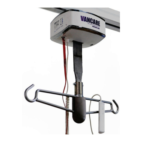
Vancare G Series User manual

Portable450
Installation and Operation Instructions
Service and Repair Manual
G-Series
Portable 450

2 Vancare
Contents
3-4
5
6
7
8
9
10
11
12
12
13
14
15
16
Introduction
Safety Instructions
Technical Specifications for Vancare G-Series Portable Lift
Anatomy of the G-Series Portable Lift
Getting Access to the G-Series Portable Lift
Replacing the G-Series Portable Lift Strap
Replacing the G-Series Portable Lift Battery
Replacing the G-Series Portable Lift Motor
Replacing the G-Series Portable Lift Limit Switch
Replacing the Emergency Switch
PCB Connections
Replacing the PCB
Pairing and Un-pairing the Hand Control to the G-Series
Portable Lift Replace the Battery on the Hand Control
Warranty 17

www.vancare.com 3
Introduction
This manual provides detailed instruction on the installation of Vancare G-Series Portable lift. Since the introduction
of ceiling mounted patient lifts, the frequency of installations has rapidly increased. This is due to greater awareness
of the risks associated with manual patient transfer and repositioning, which has led to the enforcement of more
strict lifting regulations.
Vancare strives to consistently provide exemplary service, design, and installation to all of its customers. In an ever
more competitive market, it is important to standardize installation techniques, thus ensuring that the highest
standards of quality and safety are met.
The methods described in this manual are intended for use by employees of Vancare or its authorized agents.

7.338
7.315
A A
B B
4
4
3
3
2
2
1
1
Front
Back
0.8341”
1.6256”
4 Vancare
SYMBOLS USED IN THIS MANUAL
Symbol Reference Title
!ISO 7000-0434A Caution risk of danger
TUV Certified by TUV
IEC 60417-5840 Type BF Applied Part
CE Certific tion of Conformity
ISO 7010-M002 Refer to instruction manual/booklet
Vancare Inc. Emergency Lowering
N/A N/A
!WARNING: This symbol is intended to alert the user of hazard or unsafe practices, which could result in
serious bodily harm.
MARKINGS
The G-Series Portable Lift 450 are designed to comply with the following Standards:
Standard(s): CAN/CSA-C22.2 No. 60601-1:08 Medical Electrical Equipment – Part 1: General requirements for
basic safety and essential performance. ISO10535:2006 Hoists for the transfer of disables persons
– Requirements and Test Methods. CAN/CSA-C22.2 60601-1-11:2-15 home use environments.
Product: Vancare G-Series Portable Lift
Brand Name: G-Series
Models: 450 lbs
Introduction
Vancare
Email: [email protected]
1. 800.694.4525
M
A
D
E
I
N
N
H
O
R
T
A
M
E
R
I
C
A
!
Charger: Wall Industries 36 V 1.11 A 40W
Duty Cycle: 1 Min ON / 9 Min OFF
Serial #:
Mfg. Date:
GLP450-9999
450 lbs (205 kg)
IP23
G-Series
Portable Lift 450

www.amico.com 5
Safety Instructions
!
READ THESE INSTRUCTIONS CAREFULLY OR SERIOUS INJURY MAY OCCUR
•The Vancare G-Series Portable must be installed only by personnel authorized by Vancare, Inc.
•Do not use this equipment prior to understanding the contents of this manual.
•Contents of this manual are subject to change without prior notice to users. Keep for future reference.
•Never place the Vancare G-Series Portable, track/PLP and sling(s) in control of a person who has not been properly
trained in the use and care of this equipment.
•The Vancare, Inc. Portable and associated Track/PLP and sling(s) are for transferring patients only. Never use the G-
Series for any other purpose.
•Vancare, Inc.'s Warranty is void if unauthorized personnel perform service on the Vancare G-Series Portable system.
•In facilities where more than one caregiver is be responsible for using the Vancare G-Series Portable and associated
track and slings, it is important that all caregivers be trained in the proper use of this equipment. A training program
should be established by the facility to familiarize new caregivers with this equipment.
•Do not expose the Vancare G-Series Portable directly to water. Warranty does not cover any misuse or abuse of the
Vancare G-Series Portable.
•The Vancare G-Series Portable should be inspected and maintained on a regular basis to keep it operating safely
and correctly. Refer to page 16 of this manual.
•Any accessories used with the Vancare G-Series Portable including the track/PLP and sling(s) should be checked to
ensure that they are in good working order. Check for signs of wear or fraying prior to use. Report any unusual wear or
damage immediately.
•Vancare, Inc. will not be responsible for any damage caused by misuse, neglect or purposeful destruction of the lift
and its associated components. Do not attempt to modify/alter the Vancare G-Series Portable.
•Do not in any circumstance exceed the maximum allowable load of this lift. Refer to the “Technical Specifications”
section of this manual and/or the labels on the lift.
•The installation of the lift, track and sling are certified to a maximum load. Do not exceed the maximum rated load of
any of the components.
•There is a risk of explosion if the lift is used in the presence of flammable anesthetics.
•The Vancare G-Series Portable should be decommissioned/disposed of after the recommended service lift in
accordance with local law regulations.
•If the battery case cracks and the contents of the battery contact your skin or clothing rinse immediately with warm
water.
•If the contents of the battery contact your eyes, rinse immediately with plenty of water and seek medical attention.
!
There are no known contraindications associated with the use of the Vancare G-Series Portable and its
accessories, provided they are used per our recommendations and guidelines.
However, for any independent uses of the Vancare G-Series Portable, it is extremely important that the patient is able to
receive assistance, during the transfer in the event of an equipment failure. This assistance can be provided in the form of; a
nearby qualified caregiver, a phone or other communication device.

M
A
D
E
I
N
N
O
R
T
H
A
M
E
R
I
C
A
Maximum Lifting Speed:
No load: 1 inch/second
150 lbs/68 kg: 0.6 inches/seconds
450 lbs/204 kg: 0.5 inch/seconds
Unit Weight:
6 lbs
Safe Working Load (SWL):
450 lbs
Dimensions (see diagram):
Length: 19.4" (049.27 cm)"
Height: 5.2" (13.20 cm)
Depth of Lift: 3.5" (8.89 cm)
Strap Length: 74" (187.96 cm)
Number of Lifts per Charge (Duty: 10/90):
89 with 150 lbs (25% of strap at midrange)
52 with 450 lbs (25% of strap at midrange)
Charging time: 2 - 4 Hours
Lift Case:
Flame retardant ABS
IP27 hand control - 1m water resistance
IP23 Lift - protected from ngers and water
spray less 60 degrees from vertical
Batteries:
High Capacity, Long Lasting NiMH
1 x 24V (1.6Ah)
Battery Charger:
100-240 VAC 40 Watt
Hand Control:
Wired capacitive touch hand control
Safety:
Emergency Stop: Yes
Emergency Lowering Device: Independent Electrical
Emergency Manual Lowering
Upper Limit Detection
Lower Limit Detection
Slack Tape Sensor
Free Fall Brake (Over Speed Governor)
Low Battery and Dead Battery indication
Soft Start and Stop
Overload Protection
Approvals:
CAN/CSA-C22.2 No 60601-1:08
CAN/CSA-Z10535.1:15
Expected Service Life:
22,500 cycles or 10 years. It is recommended that the lift
be replaced after this time.
The expected life of slings, batteries fuses, straps and cord
is dependent upon proper maintenance.
6 Vancare
19.4"
18.2"
5.2"
81"
Technical Specifications for Vancare G-Series Portable Lift

Emergency lowering/stop feature
Unit controls
Quick magnetic hand
control connection
Wireless bluetooth hand control
Durable all metal gears
Hook bumper
Hook bumper
Lifts up to
450 lbs!
G-Series Portable Lift
weighs
just 6 lbs!
Motor
Battery
www.vancare.com 7
Anatomy of the G-Series Portable Lift

Getting Access to the G-Series Portable450
1. Use a stand to support the lift while it is being serviced.
2. Remove three (3) screws from the case using 7/64" Allen key.
3. Open the front cover.
4. Gently pull the charger strip from the PCB.
5. Gently pull the mylar strip from the PCB and remove the cover.
8 Vancare

1. Before replacing, press the down button from either the remote or the lift to pull the strap all the way.
2. Use a small fl t screw driver to remove the screw cover.
3. Use a 5/32" Allen key and a 10M wrench to remove the strap pin.
4. Remove the washer and pull the strap pin out all the way.
5. Once the strap pin is removed, pull the strap all the way out.
6. Replace with a new strap and follow these instructions in reverse to install the new strap.
7. When installing the new strap, make sure the fold of the strap is facing the red wire on the limit switch.
www.vancare.com 9
Replacing the G-Series Portable Lift Strap

1. Make sure the lift is o. Open up the hook bumper from the right side of the tube (see page 7).
2. Using a 3/32" T handle, remove the two (2) screws.
3. After removing the two (2) screws, take off the hoo .
4. Remove one (1) more screw on top of the tube using 3/32" T handle.
5. Pull off the cap on the end of the tube on e all the screws have been taken out.
6. Gently pull out the battery from the tube to avoid damaging the wire.
7. Disconnect the battery connector.
8. Replace with a new battery and follow these instructions in reverse to install the new battery.
NOTE: Apply one (1) or two (2) drops of Blue Loctite 243 for two (2) screws on line no. 2 when installing them back.
Replacing the G-Series Portable Lift Battery
10 Vancare

www.vancare.com 11
1. Using a 3/32" Allen key, remove eight (8) screws from the left side of the tube (facing front of the lift).
Note: One (1) screw from the bottom have no lock washer.
2. Slowly pull the tube out with caution.
3. When pulling out the tube, make sure the brake wires and connector gently go through the hole on the tube.
This is to ensure the connection is not lost between the motor and the brake wires.
4. Remove three (3) screws holding the motor brake, using a 2mm Allen key.
Note: Gently put the screws back in so that they are just touching the motor brake. Do not tighten the screws.
5. Pull out the motor cable from the motor.
6. Pull the cap on the end of the tube once all the screws have been taken out.
7. Use L-type 2.5mm Allen key to loosen four (4) screws inside and remove all of them using a ball pointed Allen key.
8. Pull out the motor with force, replace with a new motor and follow these instructions in reverse to install the new motor.
Note: When installing a new motor, make sure the D-slot from the motor lines up with the motor mounting plate.
Replacing the G-Series Portable Lift Motor

1. Disconnect the limit switch harness from the PCB.
2. Remove the two (2) screws from both sides of the limit switch, using a 1.5 mm Allen key.
3. Replace the limit switch and follow these instructions in reverse to install the new limit switch.
Note: Make sure not to swap limit switches when installing them (Red and Brown wires).
Replacing the Emergency Switch
1. Remove two (2) screws and two (2) bushings from the red emergency push switch using a 3/32" Allen key.
2. Replace the push switch and follow these instructions in reverse to install the new push switch.
Replacing the G-Series Portable Lift Limit Switch
12 Vancare

1
5
3
4
2
PCB Connections
6 87
1. On/Off witch
2. Mylar
3. Battery Connector
4. Charger
5. Limit Switch
6. Motor Brake
7. Motors
8. Fixed Hand Control
www.vancare.com 13

Replacing the PCB
1. Make sure to use proper ESD equipment (wrist strap) prior to handling the PCB.
2. Open up the G-Series Portable 450 by following the steps in the section “Getting access to the G-Series Lift”.
3. Unplug all the harnesses from the PCB (battery connector, motor connector, brake connector, limit switch
connector).
4. Remove four (4) screws from the PCB, using a 1.5 mm Allen key.
5. Gently pull out the PCB from the lift.
6. Replace the PCB and follow these instructions in reverse to install the new PCB.
14 Vancare

Replacing the Hand Control
1. Disconnect the hand control connector from the circuit board.
2. Turn the grommet until the hand control cable can be pulled out.
3. Insert the cable from the new hand cotrol and reconnect to the circuit board.
www.vancare.com 15

16 Vancare
www.amico.comwww.amico.com
Amico Mobility Solutions Corporation 85 Fulton Way, Richmond Hill, ON L4B 2N4, Canada
600 Prime Place, Hauppauge, NY 11788, USA
Tel: 905.764.0800 | Fax: 905.764.0862
Warranty Policy
The primary purpose of our ceiling lift system is to safely lift, transfer and reposition a patient with a little effort as possible
for the caregiver, regardless of the room type. Vancares G-Series Lift is easy and safe to use for caregivers as well as
patients. The lift systems fit into all environments and fulfills the highest requirements of function, safety and reliability.
Vancare warrants its lifting equipment and workmanship to be free from defects for a period of two (2) years from the date
of installation. This includes tracks, lift motor, and carry bar.
Within this period, Vancare will replace any part (at no additional charge), which is deemed defective. Shipping and
installation costs after the first twelve (12) months will be borne by the customer. The following exclusions apply: the
warranty for batteries is for a period of three (3) months from the time of installation; the warranty for power supply is one
(1) year from the time of installation.
This warranty is valid only when the product has been properly installed as outlined in the Vancare specifications;
including but not limited to proper usage and servicing of systems according to factory recommendations. It does not
cover damages as a result of shipment failures, accidents, misuse, abuse, neglect, mishandling, alternation, misapplication
or damages which may be attributed to acts of God.
Vancare shall not be liable for incidental or consequential damages resulting from the use of the equipment.
All claims for warrant must first e arove Vancares Service eartment. A vali eturn oos Autoriation A
numer must e otaine from our autorie Vancare istriutor rior to commencement of an service wor or
returnin of an rouct. arrant wor wic as not een erautorie Vancare will not e reimurse.

Notes

Notes

Notes

www.vancare.com
Vancare | 1515 1st Street, Aurora NE, 68818
www.vancare.com
Manufactured for Vancare, Inc.
Other manuals for G Series
2
This manual suits for next models
1
Table of contents
Other Vancare Lifting System manuals
Popular Lifting System manuals by other brands

Golf-Lift
Golf-Lift GL-1 Instruction

Braun
Braun VISTA Series Installation & service manual

Forward Lift
Forward Lift RSM4T installation instructions

Bishamon
Bishamon NSA3500N Operation and service manual

Harmar Mobility
Harmar Mobility AL350 Installation & owner's manual

BraunAbility
BraunAbility Century 2 Service manual

ergolet
ergolet Stellar/170 User instruction

Tractel
Tractel corso PT 0,5 Original Operation and Installation Manual

Silverline
Silverline 245113 manual

Handicare
Handicare PRISM MEDICAL P600 owner's manual

Dannmar Equipment
Dannmar Equipment Max Jax Installation and operation

Costcare
Costcare L400C user manual