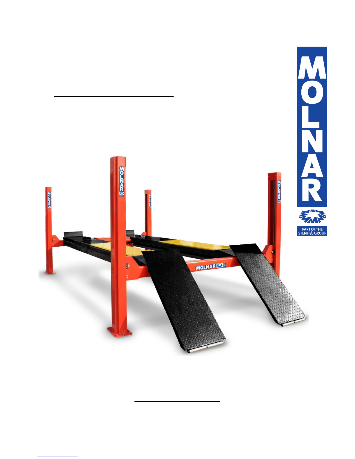
Molnar SM450 User manual

SM450 FOUR POST HOIST
5 Tonne Electro-Hydraulic Four Post Hoist
Installation Manual
Updated 14/12/2018

Page 2of 19 Molnar 4 Post Hoist SM450
Contents
Installation Instructions Page 3-16
Installer Checklist Page 17
24V Transformer Wiring Detail Page 18
Single & three Phase Wiring Diagram Page 19
Please read this manual before you get started.
You must read and understand the precautions for safety purposes and any damages that may occur to your
property.
Address: 3 Graham Street
Export Park
South Australia 5950
Ph: +61 (08) 8234 3611
Fax: +61 (08) 8234 4322
Email: [email protected]
Web: www.molnarhoists.com.au
Specifications/images subject to change without prior notice, Images and sketches are for illustration purposes only.
Before commencing
operation inspect
system components,
control, emergency
stop and safety
equipment for
condition and correct
function

Page 3of 19 Molnar 4 Post Hoist SM450
Tools Required:
Place all the components as shown to check supplied parts.
46 Weight AWH
Hydraulic Oil
10L

Page 4of 19 Molnar 4 Post Hoist SM450
TRANSPORTATION AND INSTALLATION
Preparation for installation
The hoist shall be installed on hard and flat floor made with reinforced concrete at 32MPa grade
with the thickness of 100mm minimum. The anchor bolt shall be M16 x 140mm tru-bolt and requires
16 anchor bolts.
Iccons Part No TB16140
Generally, this machine will be installed on the following conditions:
1) Supply voltage: 0.9 - 1.1 nominal supply voltage
2) Source frequency: 0.99 - 1.01 nominal frequency
3) Ambient temperature: 50C - 400C
4) Altitude: shall be at altitudes up to 1000m above mean sea level
5) Relative humidity: not exceed 50% at 40C
6) Atmosphere: Free from excessive dust, acid fume, corrosive gases and salt.
7) Avoid exposing to direct sunlight or heat rays which can change the environmental
temperature.
8) Avoid exposing to abnormal vibration.
9) Electrical equipment shall withstand the effects of transportation and storage temperature
within a range of -25°C to 55°C and for short periods not exceeding 24 hours at up to +70°C.

Page 5of 19 Molnar 4 Post Hoist SM450
Installation Process
Layout Reference Diagram
A - Run up ramps
B - Control platform
C - Non-control platform
D - Transverse beam control end
E - Transverse beam non-control end
F - Control post
G - Power pack
H - Non-control post
J - Jacking beam
Placing hoist on the installation location using timber under the platforms and transverse beams
1) Place the main parts on the appropriate position in reference to the above layout diagram.

Page 6of 19 Molnar 4 Post Hoist SM450
Assembling Transverse Beam for Platforms
1. Take the pins fixing guide block, pull out the pins and take out the transverse beam pulleys (4
positions)
2. Remove the wood pieces inside the platform which are holding the cables inside. Cut the cable ties
and pull out the large black conduit and tighten the nut to the side of the platform.
3. Connect the lock cables into each end of the transverse beams.

Page 7of 19 Molnar 4 Post Hoist SM450
4. Take out the control platform cable and put it to the control end transverse beam. This is best done
with 2 people, one at each end of the platform pulling out each cable (one in each hand).
NOTE! Fix nuts on each end of the cables to protect the thread from damage
5. Starting with the non-control end transverse beam, bring the cables through the ends of the
transverse beam and reassemble the pulleys in the reverse order that they were disassembled.
6. Attach the platforms to the non-control transverse beam.

Page 8of 19 Molnar 4 Post Hoist SM450
7. Install the front wheel stop on each platform.
8. Moving to the control transverse beam, bring cables through the ends and reassemble the transverse
beam pulleys.
9. Attach the rear of the platforms to the control transverse beam.

Page 9of 19 Molnar 4 Post Hoist SM450
Assembling the Lock Rails and Posts
10. Square up the now assembled transverse beam and platform to ensure square and level.
11. Place the lock rails through the transverse beam ends and locate in the hole at the bottom of the
posts.
NOTE! When assembling the lock rail, place the round part of the rail holes facing away from the post.
NOTE! Check that the lock rail bottom is located in the hole on base plate/ bottom of post.
NOTE! Post with lock sticker should be placed as the front control side so easily visible at controls, as
can be seen in the Figure below:
12. Before setting up the posts, put the lock rail fixing full-thread bolts to the top of the posts.
13. Put the bottom of the lock rail to the base hole as previously mentioned and set up the post.

Page 10 of 19 Molnar 4 Post Hoist SM450
14. Fasten:
-2 (a) nuts (16mm) as shown in the figure below, fasten the upper nut clockwise and the lower nut
counter clockwise, maintaining approx. space to the lock rail for 45-60mm (guideline only).
-2 (b) nuts (11.5mm) each to opposite direction, maintaining 2-3 threads (3mm) between the
nuts.
-Fix (c) nut tight to the lock rail.
15. Set up the posts, maintaining the space of approx. 45-60mm between the fixing plate of the top of the
post and the lock rail bracket.

Page 11 of 19 Molnar 4 Post Hoist SM450
16. Shim the posts as required, drill concrete holes and install anchor bolts, fasten the nuts lightly.
NOTE! Shim up baseplates so that posts are vertical. As much baseplate surface should be in contact
with the floor as possible. Molnar recommends at least 50% surface to floor contact, especially in the
middle of the baseplate which must be in contact with the floor or shimmed.
Part Number SM450-S-15 (Post Base Plate for Levelling available)

Page 12 of 19 Molnar 4 Post Hoist SM450
17. Place the spirit level on the posts and using shims, adjust the posts to be vertical to the ground in all 4
posts.
Set the posts so that guide blocks lightly contact and hold the posts when lifting up/down the
platforms.
Adjust vertically and level the 4 posts and then tighten the anchor nuts. Raise the platform to the first
or second lock position and recheck platform levels.

Page 13 of 19 Molnar 4 Post Hoist SM450
18. Attach the limit switch to the bracket and assemble to the lock rail as shown. Re-adjust the height as
required on commissioning.
NOTE! Ensure the bracket is tightly fitted to lock rail and doesn’t slide up or down.
19. Install the cable end through the hole in the top of the post plate and fasten both nuts together as
shown below on top of the post plate.
20. Attach the conduit holder bracket, air regulator and control box to the post. Then attach the black
conduit end to the holder bracket.

Page 14 of 19 Molnar 4 Post Hoist SM450
21. Mount the red power pack mounting plate to the post. Attach the motor mount and rubber mounts
to the power pack and attach to the post as shown in the image below. Remove tank and fill with 10L
of hydraulic oil and replace. Connect the hydraulic hose to the power pack.
22. There are 4 top post covers included (one for each post). The cover with the extra holes is for the
control post, attach the 24V transformer to this cover and then to the top of the control post.
NOTE! Transformer Wiring detail found in the appendix of this manual.

Page 15 of 19 Molnar 4 Post Hoist SM450
All Electrical Work to be Performed by a Licensed Electrician
23. Connect the main plate conduit tube and the control panel cable with the connection cable (purple)
and assemble the power pack tank cover. (Connection line, tank cover –power pack front vinyl cover)
24. Connect the power pack main supply.
NOTE! Requires 3 active and earth.
-Input voltage tolerance should be ±10%
-Frequency tolerance should be ±1%
-There must be a 10A over current protector installed in the input power line.
-The diameter of power supply cable should be 2.5 mm2
-Bind the hydraulic hose and cables with cable ties.
Levelling the Cables
25. Turn on the hoist and raise up the hoist and press the locking switch to tighten the cable. (Raise the
hoist to the position comfortable to work under the platform)
26. Fasten the cable clamp on the cylinder fixing cable and the drive plate.
NOTE! Clamps must be tight, retighten again at the end of the installation.
NOTE! Lubricate the cylinder rod.
NOTE! To avoid the cable clamps rubbing the cables, adjust and angle the cable clamps as shown
below and keep separated by approx. 10cm

Page 16 of 19 Molnar 4 Post Hoist SM450
27. For the final levelling of the platforms, raise the platforms to the 4th from bottom lock position and
then press the lock button. Pull the cables in each of the 4 posts evenly and tighten the cable end
bolts with a spanner.
NOTE! It is very important to recheck the levels with the heaviest vehicle available (under the hoist
capacity of 5000kg)
28. Install the other top post covers and the transvers beam pulley covers.
29. Assemble the run-up ramps and lift into position on the platforms and slide the pins through and fit
circlips.

Page 17 of 19 Molnar 4 Post Hoist SM450
Installer Checklist
Installer must complete (tick) the following list after installing this Molnar hoist:
legal clearances around hoist
floor is suitable and within manufactures specifications
cables, pulleys and/or hoses are free of any damage
safety devices, limit switches and controls have been checked for correct operation
hydraulic system checked and leak free at time of installation
hoist tested without and with load as per manufactures specifications
hoist has been lubricated and adjusted as per manufactures specifications
log book use has been explained to owner/operator and initial details completed
the client representative has been shown and instructed in the correct operation and
maintenance of the hoist
Distributor (vendor)
Hoist
Company
Installation Date
Branch
Model Number
Serial Number
Hoist Owner
Installer Details
Business
Name
Name
Company
Position
Signature
Signature
These records should be retained for administrative and warranty assistance.
Log books are available from Molnar Services or Molnar Hoists distributors.
Part Number: 8209001 - Hoist Log Book Kit

Page 18 of 19 Molnar 4 Post Hoist SM450
Molnar SM450
Transformer Wiring 24V Low Voltage Control
(Hoist Serial Number 4P5D0142 onwards)
Black
Blue
Yellow/Green
Red
White

Page 19 of 19 Molnar 4 Post Hoist SM450
Molnar SM450
Single and Three Phase Wiring Diagram
(Hoist Serial Number 4P5D0142 Onwards)
Other manuals for SM450
1
Table of contents
Other Molnar Lifting System manuals