SIIG AV-GM0743-S1 User manual

2x4 HDMI 1.3 Matrix
P/N: AV-GM0743-S1

~ 1 ~
Safety and Notice
The AV-GM0743-S1 2x4 HDMI 1.3 Matrix has been tested for conformance to safety
regulations and requirements, and has been certified for international use. However, like all
electronic equipments, the AV-GM0743-S1 should be used with care. Please read and follow the
safety instructions to protect yourself from possible injury and to minimize the risk of damage to
the unit.
Follow all instructions and warnings marked on this unit.
Do not attempt to service this unit yourself, except where explained in this manual.
Provide proper ventilation and air circulation and do not use near water.
Keep objects that might damage the device and assure that the placement of this unit is on a
stable surface.
Use only the power adapter and power cords and connection cables designed for this unit.

~ 2 ~
The 2x4 HDMI 1.3 Matrix provides the most flexible and cost effective solution in the market
to route high definition video sources plus multi-channel (up to 7.1 channel) digital audio from
any of the two HDMI sources to the any four displays at the same time. This solution is well
suited for use in home theater, conference room presentation systems, or other similar setting
or application.
Introduction
HDMI
cable
4x HDMI Output
PS3
HDMI camcorder
2x HDMI Input
AV-GM0743-S1
Blu-ray disc player
TiVo
PC with HDMI output
HDTV
HDMI projector
HDMI monitor

~ 3 ~
Features
State-of-the-art Silicon Image (founder of HDMI) chipset embedded for upmost compatibility
and reliability
HDMI 1.2a/1.3c* compliant
HDCP compliant
Allows any source to be displayed on multiple displays at the same time
Allows any HDMI display to view any HDMI source at any time
Supports 7.1 channel digital audio
Supports default HDMI EDID and learns the EDID of displays
The matrix master can switch every output channels to any HDMI inputs by push button, IR
remote control, or RS-232 control
*HDMI 1.2a for AV-GM0743-S1
v1.2
HDMI 1.3c for AV-GM0743-S1
v1.3

~ 4 ~
Specifications & Package Contents
Model Name
AV-GM0743-S1
Technical
Role of usage
True 2x4 matrix
HDMI compliance
[AV-GM0743-S1 v1.2] –HDMI 1.2a [AV-GM0743-S1 v1.3] –HDMI 1.3c
HDCP compliance
Yes
Video bandwidth
[AV-GM0743-S1 v1.2] –Single-link 165MHz [4.95Gbps]
[AV-GM0743-S1 v1.3] –Single-link 225MHz [6.75Gbps]
Video support
480i / 480p / 720p / 1080i / 1080p60 12-bit color
Audio support
Surround sound (up to 7.1ch) or stereo digital audio
ESD protection
[1] Human body model —±19kV [air-gap discharge] & ±12kV
[contact discharge]
[2] Core chipset —±8kV
PCB stack-up
4-layer board [impedance control —differential 100; single 50]
Input
2x HDMI + 1x RS-232
Output
4x HDMI
HDMI Input
selection
Push button / IR remote / RS-232
IR remote control
Electro-optical characteristics: = 25/ Carrier frequency: 36~40kHz
HDMI connector
Type A [19-pin female]
RJ-45 connector
WE/SS 8P8C with 2 LED indicators [TMDS & DDC channels]
RS-232 connector
DE-9 [9-pin D-sub female]
DIP switch
[SW1~SW4] 2-pin for EDID learning, audio/video settings
[SW Main] 4-pin operation mode & firmware update
Mechanical
MA-5144
Housing
Metal enclosure
Dimensions
(L x W x H)
Model
340 x 110 x 44mm [1’1.4”x4.3”x1.7”]
Package
490 x 225 x 70mm [1’7.3”x8.9”x2.8”]
Carton
510 x 380 x 252mm [1’8”x1’3”x9.9”]
Weight
Model
1075g [2.4lbs]
Package
2090g [4.6lbs]
Fixedness
1U rack-mount with ears and wall hanging holes
Power supply
5V 6A DC
Power consumption
20 Watts [max]
Operation
temperature
0~40C [32~104F]
Storage temperature
-20~60C [-4~140F]
Relative humidity
20~90% RH [no condensation]
Package Contents
1x AV-GM0743-S1
2x Rack-mounting ears
1x User Manual
1x 5V 6A power adapter

~ 5 ~
1x IR remote

~ 6 ~
Front Panel
1. Port 1: Push button for input switch on output port 1.
2. Select 1-2: Green LED lights up indicating the selected HDMI input for output port 1.
3. HP1: Hot-plug LED lights up indicating a valid connection status on output port 1.
4. Port 2: Push button for input switch on output port 2.
5. Select 1-2: Green LED lights up indicating the selected HDMI input for output port 2.
6. HP2: Hot-Plug LED lights up indicating a valid connection status on output port 2.
7. Port 3: Push button for input switch on output port 3.
8. Select 1-2: Green LED lights up indicating the selected HDMI input for output port 3.
9. HP3: Hot-Plug LED lights up indicating a valid connection status on output port 3.
10. Port 4: Push button for input switch on output port 4.
11. Select 1-2: Green LED lights up indicating the selected HDMI input for output port 4.
12. HP4: Hot-Plug LED lights up indicating a valid connection status on output port 4.
13. INPUT 1-2: Plug LED lights up indicating a valid connection status on output port 4
14. IR: IR receiver to receive IR commands from the matrix’s IR remote control
15. Power: Power LED lights up indicating power-on status.
Panel Descriptions
2
1
3
5
4
6
8
7
9
11
10
12
13
14
15

~ 7 ~
Rear Panel
16. ON –OFF: Power ON/OFF switch.
17. RS-232: Connect to a PC for RS-232 serial control.
18. +5V DC: Connect to a 5V DC power supply unit and with a C5-type power cord.
19. SW Main: 4-pin DIP switch for operation and firmware update. See DIP Switch section in p.9
for more detail.
20. SW1 & SW2: 2-pin DIP switch for EDID and audio/video settings. See DIP Switch section in p.8
for more detail.
21. IN1 & IN2: HDMI input 1 and 2 to connect to HDMI source devices.
22. OUT 1: HDMI over CAT5e/6 via TMDS and DDC RJ-45 ports for HDMI output 1.
23. OUT 2: HDMI over CAT5e/6 via TMDS and DDC RJ-45 ports for HDMI output 2.
24. OUT 3: HDMI over CAT5e/6 via TMDS and DDC RJ-45 ports for HDMI output 3.
25. OUT 4: HDMI over CAT5e/6 via TMDS and DDC RJ-45 ports for HDMI output 4.
16
17
18
19
20
21
22
23
24
25

~ 8 ~
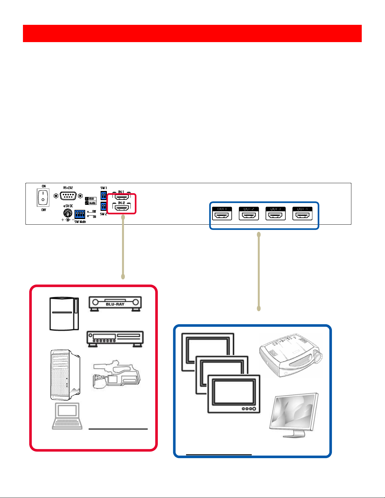
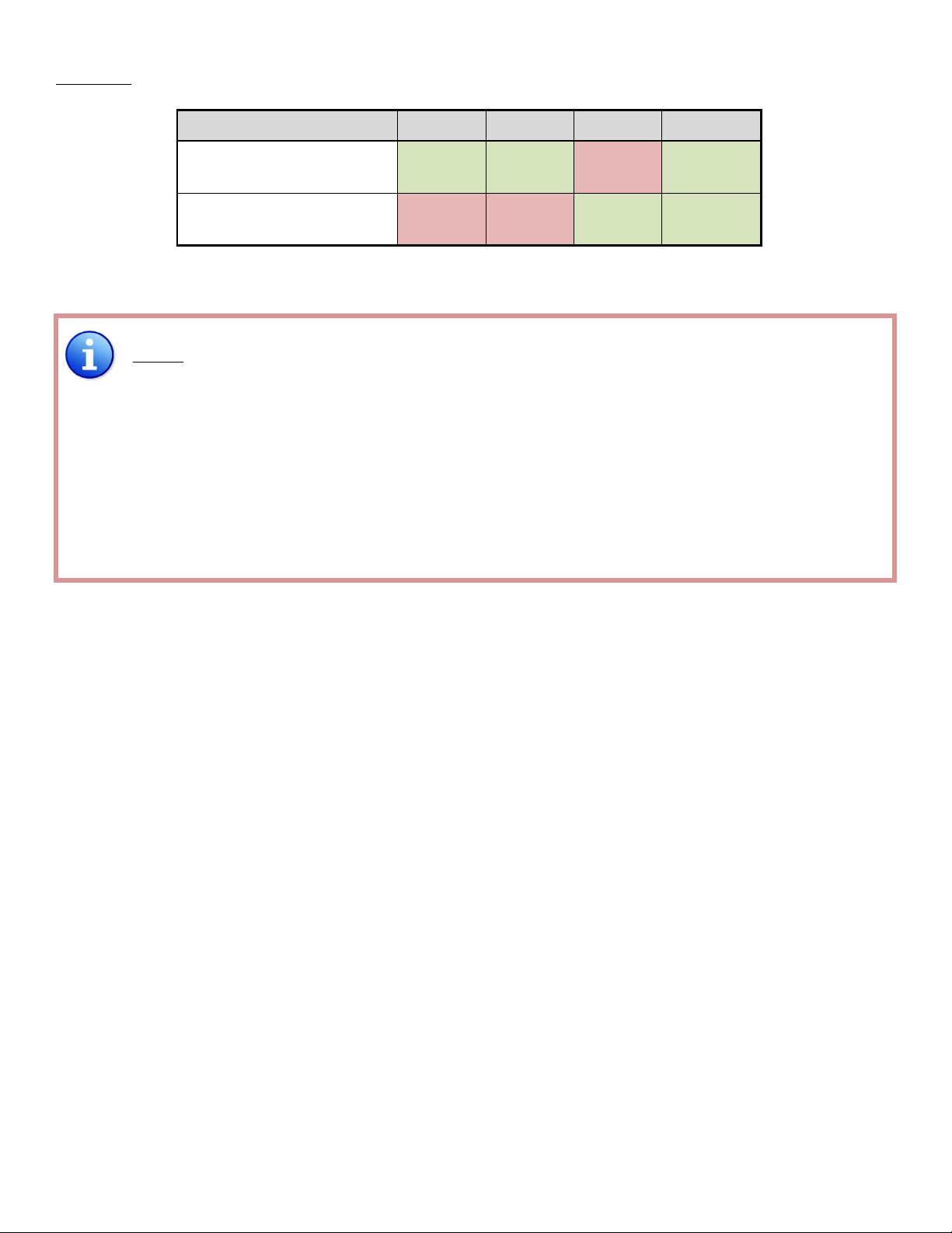
SW1-SW2for EDID/Audio
Note
1
If the HDTV shows video but without audio, please try to set audio mode to stereo.
2
Factory default of SW1-SW2: Pin#1-OFF
[] &
Pin#2- OFF
[] for 1080p with stereo.
3
If you encounter any unsolved audio/video output problem during system installation,
please turn any SW1-SW2 to Pin#1-OFF
[] &
Pin#1-ON
[]
, for safe mode to enforce the
most compatible 720p stereo output for system check. However, the safe mode cannot be
initiated if your HDMI source is set to enforce 1080p output. In this case, please reconfigure
your HDMI source to all resolution output for troubleshooting.
4
Bypass means the matrix will maintain playing the original format of HDMI signals in video
and perhaps audio. By setting at this mode, the users may encounter compatibility issue
among different kinds of HDMI sources and displays. If you cannot get the audio and/or
video output normally at the system installation, please change the DIP switch setting to
default mode or even safe mode to verify the functionality of the device.
5
Set Pin#1 at ON
[]
first then connect the HDMI Input to HDTV through a HDMI cable. Wait
for 20 seconds. The EDID learning procedure will be finished. If you want to learn the EDID
from another HDTV, you must set Pin#1 at OFF
[]
first and repeat this procedure.
DIP Switch
Position
Video
Audio
Description
Pin#1
Pin#2
OFF []
OFF []
Up to
1080p
Stereo
1
Default Mode2–Up to 1080p & stereo audio output
for most HDTVs
OFF []
ON []
Up to
720p /
1080i
Stereo
Safe Mode3–Enforce the system output at
720p/1080i video and stereo audio for basic
compatibility among HDTVs
ON []
OFF []
Bypass4
Bypas
s4
EDID Learning Mode5–for learning EDID from the
display while playing any received HDMI audio format
ON []
ON []
Bypass
Stereo
EDID Learning & Stereo Mode5–for learning EDID
from the display while enforcing stereo output if any
HDTV cannot play surround sound normally
DIP Switch

~ 9 ~
SW Main for firmware update (for technical support only)
DIP Switch Position
Pin#1
Pin#2
Pin#3
Pin#4
Normal Operation
Mode6
OFF []
OFF []
ON []
OFF []
Firmware Update
Mode7
ON []
ON []
OFF []
OFF []
Note
6
Factory default for SW Main: Pin#1-OFF
[]
, Pin#2-OFF
[]
, Pin#3-ON
[]
, Pin#4-OFF
[]
.
PLEASE MAINTAIN THIS SETTING AT ANYTIME FOR REGULAR USE!
7
Sequence for firmware update
[1]. Power off the matrix unit.
[2]. Set the SW Main DIP switch position to Firmware Update Mode [].
[3]. Power on the matrix unit.
[4]. Power off the matrix unit.
[5]. Set the DIP switch position to Normal Operation Mode [].
[6]. Power on the matrix unit.

~ 10 ~
MX-5124H
1. Connect all sources to HDMI Inputs on the 2x4 HDMI Matrix
2. Connect all outputs to HDMI devices
3. Connect the +5V 6A DC power supply to the 2x4 HDMI Matrix
4. Power on the 2x4 HDMI Matrix MX-5124H
The EDID learning function is only necessary whenever you encounter any display on the HDMI
output port that cannot play audio and video properly. Because the HDMI source devices and
displays may have various level of capability in playing audio and video, the general principle is
that the source device will output the lowest standards in audio format and video resolutions to
be commonly acceptable among all HDMI displays. In this case, a 720p stereo HDMI signal
output would be probably the safest choice. Nevertheless, the user can force the matrix to learn
the EDID of the lowest capable HDMI display among others to make sure all displays are capable
to play the HDMI signals normally by performing the procedures stated below.
SW1 / SW2’s pin 1 must be set at ON for EDID Learning Mode
DIP Switch Position
Video
Audio
Description
Pin 1
On []
Bypas
s
Stereo
EDID Learning
For learning EDID from the receiver
Manually connect displays to HDMI input ports
Hardware Installation
EDID Learning

~ 11 ~
1. Power up the matrix master unit. Connect the HDMI display that its EDID needs to be learned
to either/both of the HDMI INPUT 1 & INPUT 2 port where your source device has trouble to
show the picture normally.
2. To learn the display’s EDID for source device connected to respective HDMI INPUT 1-INPUT 2
port, pull both pins of respective DIP switch SW1-SW2 up-and-down to stay at on-on [-]
and wait for about 5 seconds to complete the EDID learning process. You DON’T NEED to pull
up the DIP switch again unless you want to learn another display’s EDID by pulling both DIP
switch pin 1 & pin 2 of SW1 / SW2 up-and-down one more time.
3. Repeat step1 & step2 if you want to learn the EDID of this HDMI display on any other HDMI
input ports that have same trouble playing the audio/video properly.
Method A: Push Button
Push the red switch button of the output port to select the input channels.
Method B: IR Remote Control
a. Choose the output port you want to make channel
switch from OUT 1 to OUT 4 then press 1 or 2 channel
button to choose the HDMI input source shown on the
chosen output display.
Method C: Software Control through RS-232
Operation and IR Control

~ 12 ~
Input-Output Channel Setup:
A. Input Output
Click on either input button then click on the output buttons to assign
them playing the selected input channel.
B. Output Input
Click on either output button then a quick selection table of inputs
will show up. Users can therefore easily select the input for each output.
Function buttons:
Setting: Set the ID of this device for cascading or other
purposes in the future.
1
2
3
4
5
6
7
8
2

~ 13 ~
Scan: Choose COM port number and Device ID for scan.
Then tick “Scan Device ID” and press “Scan” button
to know which COM port is connected based on
this Device ID.
Linkage: Indicate the connection status.
Open: Open the COM port after scan to establish the connection between PC and the matrix.
Close: Release the COM port after scan.
Mapping: Click on this button, a quick selection table of inputs will show up. Users can
therefore easily select the output video for each input by pressing “Output” button.
Fast Select: Provide the fast setup between inputs and outputs of the matrix. “Input1 – All
Output” means all four outputs playing HDMI input 1. “Input2 – All Output” means all
four outputs playing HDMI input 2.
7
3
4
5
6
8

~ 14 ~
RS-232 transmission Format
Baud rate: 9600
Data bit: 8
Parity: None
Set Command
Command Code
Response
Description
Data
Check SUM
ACK
SET
0x08 0x4d 0x41 0x51 0x44 0x05
*0x01~0xff
0x31~0x2f
0xaa
SET MA-5144 Device
ID
0x0c 0x4d 0x41 0x51 0x44
Device_Id 0x02 port1 port2 port3
port4
0x0c+…+port4
0xaa
Set MA-5144 Source
Mapping of Output
Port
Status Command
Command Code
Response
Description
Data
Check
SUM
Get Status
Check
SUM
Status
0x05 0x4d 0x4f 0x44
0xe5
0xaa 0x06 0x4d
0x41 0x51 0x44
0x29
Get Device Type
(MA-5144)
0x07 0x4d 0x41 0x53
0x57 0x04
0x43
0xaa 0x3
0x01~0xff
0x04~0x02
Get Device ID
0x08 0x4d 0x41 0x51
0x44 *0x01~0xFF
0x01
0x2e~0x
2c
0xaa 0x06 port1
port2 port3
port4
0x06 +
port1~port4
Get Source Mapping of
Output Port
0x08 0x4d 0x41 0x51
0x44 *0x01~0xFF
0x04
0x30~0x
2e
0xaa 0x08 0x56
0x33 0x2e 0x30
0x31 0x61
0x81
Software Version
V.3.01a
Check sum:
Check sum = (Data value sum)%256 The check sum of response is not included 0xaa.
0x01 ~ 0xFF:
This data is device ID. The Device ID saved in the device, if the device ID of the controlled
device is 0xff , the device will ignore its own ID and carry out the commands.
RS-232 Commands

~ 15 ~
Default Custom Code —IR2 Code: 00
FF
Function
0x17
0x0A
0x0C
POWER
0x02
SOURCE SEL. 1
0x54
SOURCE SEL. 2
0x55
F1
0x57
F2
0x58
F3
0x59
F4
0x06
Output Port 1
Input 1- 0x18
Input 2 - 0x5B
Output Port 2
Input 1 - 0x1B
Input 2 - 0x5A
Output Port 3
Input 1 - 0x0E
Input 2 - 0x0D
Output Port 4
Input 1 - 0x1C
Input 2 - 0x1D
Custom Code —IR3 Code: 0x12 0x21
Output 1
Output 2
Output 3
Output 4
Source 1
0xA1
0xB1
0xC1
0xD1
Source 2
0xA2
0xB2
0xC2
0xD2
Custom Code —IR4 Code: 0x13 0x31
Output 1
Output 2
Output 3
Output 4
Source 1
0xAE
0xBE
0xCE
0xDE
Source 2
0xAD
0xBD
0xCD
0xDD
Note: Using terminal to set Custom Code
Example: Set custom code from 0x01 0xEE to 0x13 0x31
>>IR4 -------------- command (using RS-232 terminal command mode)
>>IR4 -------------- echo
IR Direct Code
—

~ 16 ~
Command
Custom Code
IR2
0x00 0xFF
IR3
0x12 0x21
IR4
0x13 0x31
For further information, please check the installation CD.

~ 17 ~
The SELLER warrants the AV-GM0743-S1 2x4 HDMI 1.3 Matrix to be free from defects in the
material and workmanship for 3 years from the date of purchase from the SELLER or an
authorized dealer. Should this product fail to be in good working order within 3 years warranty
period, the SELLER, at its option, repair or replace the unit, provided that the unit has not been
subjected to accident, disaster, abuse or any unauthorized modifications including static
discharge and power surge. This warranty is offered by the SELLER for its BUYER with direct
transaction only. This warranty is void if the warranty seal on the metal housing is broken.
Unit that fails under conditions other than those covered will be repaired at the current price
of parts and labor in effect at the time of repair. Such repairs are warranted for 90 days from the
day of reshipment to the BUYER. If the unit is delivered by mail, customers agree to insure the
unit or assume the risk of loss or damage in transit. Under no circumstances will a unit be
accepted without a return authorization number.
The warranty is in lieu of all other warranties expressed or implied, including without
limitations, any other implied warranty or fitness or merchantability for any particular purpose,
all of which are expressly disclaimed.
Proof of sale may be required in order to claim warranty. Customers outside Taiwan are
responsible for shipping charges to and from the SELLER. Cables and power adapters are limited
to a 30 day warranty and must be free from any markings, scratches, and neatly coiled.
The content of this manual has been carefully checked and is believed to be accurate.
However, The SELLER assumes no responsibility for any inaccuracies that may be contained in
this manual. The SELLER will NOT be liable for direct, indirect, incidental, special, or
consequential damages resulting from any defect or omission in this manual, even if advised of
the possibility of such damages. Also, the technical information contained herein regarding the
AV-GM0743-S1 features and specifications is subject to change without further notice.
Limited Warranty

~ 18 ~
April, 2018
Support
For more info or tech support
http://www.siig.com/support
Table of contents
Other SIIG Matrix Switcher manuals

SIIG
SIIG 4x2 HDMI User manual

SIIG
SIIG AV-GM07J3-S1 User manual

SIIG
SIIG AV-GM06Y3-S1 User manual

SIIG
SIIG AV-GM07R3-S12 User manual

SIIG
SIIG AV-GM0823-S1 User manual

SIIG
SIIG CE-H24W11-S1 User manual

SIIG
SIIG AV-GM0803-S1 User manual

SIIG
SIIG AV-GM0703-S1 User manual

SIIG
SIIG AV-GM0733-S1 User manual

SIIG
SIIG AV-GM07M3-S1 User manual

SIIG
SIIG AV-GM07X3-S1 User manual

SIIG
SIIG AV-GM0843-S1 User manual

SIIG
SIIG CE-H21F11-S1 User manual

SIIG
SIIG AV-GM07U3-S1 User manual

SIIG
SIIG AV-GM0783-S1 User manual

SIIG
SIIG AV-GM06X3-S1 User manual

SIIG
SIIG MA-1088D User manual

SIIG
SIIG AV-GM07A3-S1 User manual

SIIG
SIIG AV-GM07C3-S1 User manual

SIIG
SIIG CE-H23H11-S1 User manual


