Crestron Electronics DM-NVX-E30 User manual

DM NVX® Network AV
Encoders/Decoders
DM-NVX-E30
DM-NVX-D30
DM-NVX-E30C
DM-NVX-D30C
DM-NVX-D80-IOAV
Product Manual
Crestron Electronics, Inc.

Original Instructions
The U.S. English version of this document is the original instructions.
All other languages are a translation of the original instructions.
The product warranty can be found at www.crestron.com/legal/sales-terms-conditions-warranties.
The specific patents that cover Crestron products are listed at www.crestron.com/legal/patents.
Certain Crestron products contain open source software. For specific information, visit
www.crestron.com/legal/open-source-software.
Crestron, the Crestron logo, 3-Series, Crestron Toolbox, Crestron XiO Cloud, DigitalMedia, DM NVX, and DM NVX Director
are either trademarks or registered trademarks of Crestron Electronics, Inc. in the United States and/or other countries.
Dolby and Dolby Atmos are either trademarks or registered trademarks of Dolby Laboratories in the United States and/or
other countries. DTS HD and DTS:X are either trademarks or registered trademarks of DTS, Inc. in the United States and/or
other countries. HDMI and the HDMI logo are either trademarks or registered trademarks of HDMI Licensing LLC in the
United States and/or other countries. Active Directory is either a trademark or registered trademark of Microsoft
Corporation in the United States and/or other countries. Intel is either a trademark or registered trademark of Intel
Corporation in the United States and/or other countries. DisplayPort is either a trademark or registered trademark of Video
Electronics Standards Association in the United States and/or other countries. Other trademarks, registered trademarks,
and trade names may be used in this document to refer to either the entities claiming the marks and names or their
products. Crestron disclaims any proprietary interest in the marks and names of others. Crestron is not responsible for errors
in typography or photography.
©2021 Crestron Electronics, Inc.

Product Manual – DOC. 8425D Contents •i
Contents
Introduction.................................................................................................................................... 1
Physical Description......................................................................................................................2
DM-NVX-E30 and DM-NVX-D30 ........................................................................................................... 2
Front Panel, DM-NVX-E30................................................................................................................ 2
Front Panel, DM-NVX-D30 ............................................................................................................... 3
Rear Panel, DM-NVX-E30 and DM-NVX-D30...............................................................................4
DM-NVX-E30C ........................................................................................................................................... 5
DM-NVX-D30C...........................................................................................................................................6
DM-NVX-D80-IOAV .................................................................................................................................. 7
Front Panel ........................................................................................................................................... 7
Rear Panel.............................................................................................................................................8
Status and Configuration........................................................................................................... 8
DMF-CI-8 Chassis Details........................................................................................................................ 9
Using the Web Interface....................................................................................................................9
Using SIMPL Windows .......................................................................................................................9
DM NVX Director Virtual Switching Appliance..................................................................................10
Crestron XiO Cloud Service Connection ..............................................................................................11
Fan Control ............................................................................................................................................... 12
Using the Web Interface.................................................................................................................. 12
Using SIMPL Windows ..................................................................................................................... 13
Automatic Point-to-Point Connectivity .............................................................................................. 13
Using the Web Interface.................................................................................................................. 13
Using SIMPL Windows ..................................................................................................................... 14
Stream Statistics..................................................................................................................................... 14
Using the Web Interface.................................................................................................................. 14
Using SIMPL Windows ..................................................................................................................... 15
Image Preview .......................................................................................................................................... 15
Using the Web Interface.................................................................................................................. 16
Using SIMPL Windows ..................................................................................................................... 17
Multicast TTL (Time-to-Live)................................................................................................................. 17
Using the Web Interface.................................................................................................................. 18
Using SIMPL Windows ..................................................................................................................... 19
DSCP (Differentiated Services Code Point) ...................................................................................... 19
Adaptive Bit Rate..................................................................................................................................... 21
Using the Web Interface.................................................................................................................. 21
Using SIMPL Windows .....................................................................................................................22
7.1 Surround Sound Audio ......................................................................................................................22
DM NAX Audio over IP (AES67) ............................................................................................................23
Using the Web Interface..................................................................................................................23
Using SIMPL Windows ..................................................................................................................... 27
Analog Audio Output ..............................................................................................................................28
Using the Web Interface..................................................................................................................28
Using SIMPL Windows .....................................................................................................................28

ii •Contents Product Manual – DOC. 8425D
Subscriptions ............................................................................................................................................29
Using the Web Interface..................................................................................................................29
Using SIMPL Windows ..................................................................................................................... 31
EDID (Extended Display Identification Data).................................................................................... 31
Background Image...................................................................................................................................34
Using the Web Interface..................................................................................................................34
Using the Web Interface..................................................................................................................38
Still Image Detection...............................................................................................................................38
USB 2.0 Routing .......................................................................................................................................39
Using the Web Interface................................................................................................................. 40
Using SIMPL Windows .....................................................................................................................42
Test Pattern Generator ..........................................................................................................................44
Using the Web Interface..................................................................................................................44
Using SIMPL Windows .....................................................................................................................47
Enterprise-Grade Security .................................................................................................................... 48
Authentication Management ........................................................................................................ 48
IEEE 802.1X Authentication ............................................................................................................49
Automatic Firmware Update ................................................................................................................ 51
IGMP Snooping........................................................................................................................... 52
Troubleshooting.......................................................................................................................... 55
Appendix: Device Discovery ...................................................................................................... 57

Product Manual – DOC. 8425D DM-NVX-E30(C)/DM-NVX-D30(C)/DM-NVX-D80-IOAV •1
Introduction
Crestron® DM NVX® network AV encoders/decoders transport ultra high-definition 4K
video with 60 Hz frame rates and 4:4:4 color sampling over standard Gigabit Ethernet.
Support for High Dynamic Range (HDR) video and HDCP 2.2 ensures high picture quality
and compatibility with a variety of media sources. Using Pixel Perfect Processing
technology, a video signal is encoded and decoded to achieve imperceptible end-to-end
latency of less than 1 frame.
DM-NVX-E30(C) devices consist of the DM-NVX-E30 surface-mountable endpoint
and the DM-NVX-E30C card, which function as encoders (transmitters) only.
DM-NVX-D30(C) devices consist of the DM-NVX-D30 surface-mountable endpoint and
the DM-NVX-D30C card, which function as decoders (receivers) only. The DM-NVX-D80-
IOAV also functions as a decoder only and is compatible with the Intel® OPS (Open
Pluggable Specification).
Compact in design, the DM-NVX-E30 and DM-NVX-D30 are designed to mount to a flat
surface such as a wall. The DM-NVX-E30C and DM-NVX-D30C are designed to occupy
the DMF-CI-8 card chassis. The DM-NVX-D80-IOAV is designed for installation into the
OPS slot of an OPS-supported display.
NOTE: The DM-NVX-D30, DM-NVX-D30C, and DM-NVX-D80-IOAV do not support
video scaling.
This manual provides information about the following:
•Physical description
•Status and configuration
•IGMP snooping
•Troubleshooting
In addition, information about device discovery of a DM NVX device using Crestron
Toolbox™ software is provided in the appendix of this manual. For installation
information, refer to the DM-NVX-E30/DM-NVX-D30 Quick Start (Doc. 8211),
DM-NVX-E30C/DM-NVX-D30C Quick Start (Doc. 8346), or DM-NVX-D80-IOAV Quick
Start (Doc. 8526) as appropriate. For information about designing a DM NVX system,
refer to the DM NVX AV-over-IP System Design Guide (Doc. 7977).

2 •DM-NVX-E30(C)/DM-NVX-D30(C)/DM-NVX-D80-IOAV Product Manual – DOC. 8425D
Physical Description
The following sections provide information about the connectors, controls, and indicators
that are available on the DM-NVX-E30(C), DM-NVX-D30(C), and DM-NVX-D80-IOAV
devices.
DM-NVX-E30 and DM-NVX-D30
This section provides information about the front and rear panels of the DM-NVX-E30
and DM-NVX-D30.
Front Panel, DM-NVX-E30
The following illustration shows the front panel of the DM-NVX-E30.
DM-NVX-E30 Front Panel
CONSOLE: Micro USB connector, female;
USB 2.0 computer console port for setup
NV LED:Green LED, indicates that the device is transmitting and encoding
network video
OL LED: Green LED, indicates an online connection to a control system via Ethernet
LAN: 8-pin RJ-45 connector, female;
100BASE-TX/1000BASE-T Ethernet port;1
PoE+ PD (powered device) port compatible with a PoE+ compliant Ethernet switch, a
Crestron DM-PSU-ULTRA-MIDSPAN, or an approved third-party PSE;
Green LED indicates Ethernet link status;
Amber LED indicates Ethernet activity
HDMI INPUT LED: Green LED, indicates sync detection at the HDMI® input
HDMI INPUT: HDMI Type A connector, female;
HDMI digital video/audio input (DVI and Dual-Mode DisplayPort™ interface
compatible)2, 3
1The LAN port must connect to a 1000BASE-T switch in order to stream network video.
2The HDMI connection requires an appropriate adapter or interface cable to accommodate a DVI or
Dual-Mode DisplayPort signal. CBL-HD-DVI interface cables are sold separately.
3Device control via CEC (Consumer Electronics Control) requires the use of a Crestron 3-Series® or later
control system.

Product Manual – DOC. 8425D DM-NVX-E30(C)/DM-NVX-D30(C)/DM-NVX-D80-IOAV •3
AUDIO: 5-pin 3.5 mm detachable terminal block;
Balanced/unbalanced stereo line-level audio output;
Output Impedance: 200 Ohms balanced, 100 Ohms unbalanced;
Maximum Output Level: 4 Vrms balanced, 2 Vrms unbalanced
NOTE: The analog audio output is functional only when the DM-NVX-E30 is receiving
a 2-channel stereo input signal.
Front Panel, DM-NVX-D30
The following illustration shows the front panel of the DM-NVX-D30.
DM-NVX-D30 Front Panel
CONSOLE: Micro USB connector, female;
USB 2.0 computer console port for setup
NV LED: Green LED, indicates that the device is receiving and decoding network
video
OL LED: Green LED, indicates an online connection to a control system via Ethernet
LAN: 8-pin RJ-45 connector, female;
100BASE-TX/1000BASE-T Ethernet port;1
PoE+ PD (powered device) port compatible with a PoE+ compliant Ethernet switch, a
Crestron DM-PSU-ULTRA-MIDSPAN, or an approved third-party PSE;
Green LED indicates Ethernet link status;
Amber LED indicates Ethernet activity
HDMI OUTPUT LED: Green LED, indicates video signal transmission at the
HDMI output
HDMI OUTPUT: HDMI Type A connector, female;
HDMI digital video/audio output (DVI compatible)2, 3
AUDIO: 5-pin 3.5 mm detachable terminal block;
Balanced/unbalanced stereo line-level audio output;
Output Impedance: 200 Ohms balanced, 100 Ohms unbalanced;
Maximum Output Level: 4 Vrms balanced, 2 Vrms unbalanced
NOTE: The analog audio output is functional only when the DM-NVX-D30 is receiving
a 2-channel stereo input signal.
1The LAN port must connect to a 1000BASE-T switch in order to stream network video.
2The HDMI connection requires an appropriate adapter or interface cable to accommodate a DVI signal.
CBL-HD-DVI interface cables are sold separately.
3Device control via CEC requires the use of a Crestron 3-Series or later control system.
4 •DM-NVX-E30(C)/DM-NVX-D30(C)/DM-NVX-D80-IOAV Product Manual – DOC. 8425D
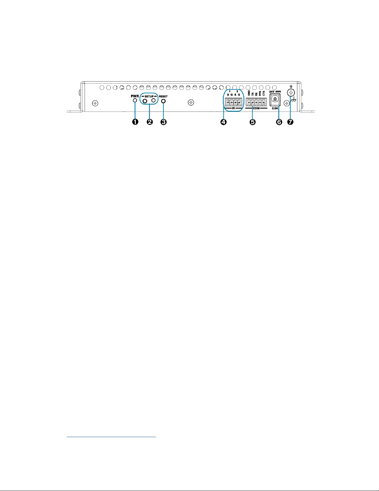
Rear Panel, DM-NVX-E30 and DM-NVX-D30
The following illustration shows the rear panel of the DM-NVX-E30 and DM-NVX-D30.
DM-NVX-E30 and DM-NVX-D30 Rear Panel
PWR: Bicolor green/amber LED, indicates operating power supplied via the power
pack (sold separately), PoE+ compliant Ethernet switch, or injector/PSE;
Lights amber while booting and green when operating
SETUP: Push button for on-screen display of IP address;
Red LED, indicates that the SETUP button is pressed and times out automatically.
RESET: Recessed push button for hardware reset
IR 1–2: 4-pin 3.5 mm detachable terminal block;
Comprises two IR/serial ports∗
IR output up to 1.1 MHz;
1-way serial TTL/RS-232 (0–5 volts) up to 19200 baud;
Crestron IRP2 emitter sold separately
COM: 5-pin 3.5 mm detachable terminal block;
Bidirectional RS-232 port;*
Up to 115.2k baud, hardware and software handshaking support
24VDC 2.0A: 2.1 x 5.5 mm DC power connector;
24 VDC power input;
Power pack included
Ground: 6-32 screw, chassis ground lug
∗Device control via IR and RS-232 requires the use of a Crestron 3-Series or later control system.

Product Manual – DOC. 8425D DM-NVX-E30(C)/DM-NVX-D30(C)/DM-NVX-D80-IOAV •5
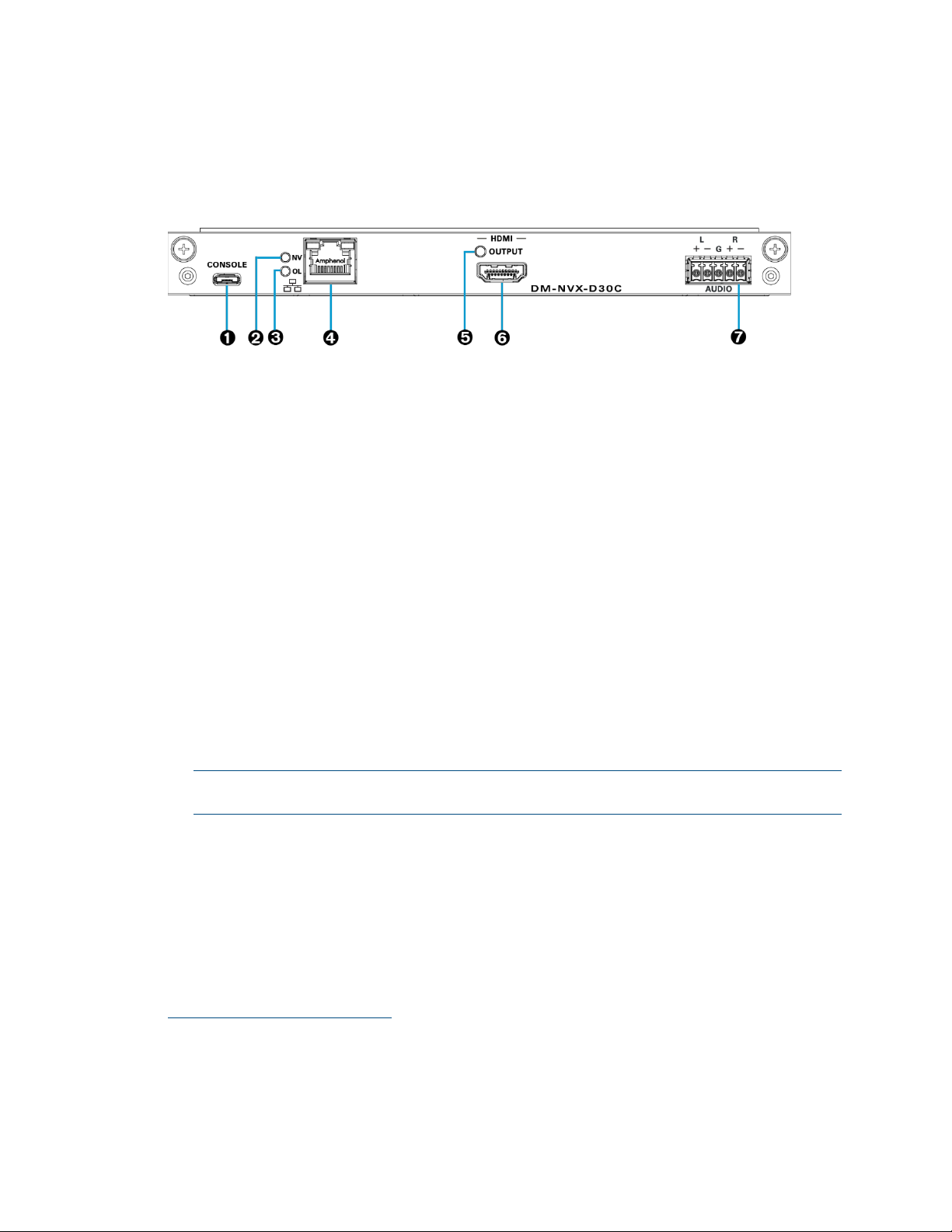
DM-NVX-E30C
The following illustration shows the connectors, controls, and indicators that are
available on the DM-NVX-E30C.
DM-NVX-E30C
CONSOLE: Micro USB connector, female;
USB 2.0 computer console port for setup
NV LED: Green LED, indicates that the device is transmitting and encoding
network video.
OL LED: Green LED, indicates an online connection to a control system via Ethernet
LAN: 100BASE-TX/1000BASE-T Ethernet port;1
Green LED indicates Ethernet link status;
Amber LED indicates Ethernet activity
HDMI INPUT LED: Green LED, indicates sync detection at the HDMI input
HDMI INPUT: HDMI Type A connector, female;
HDMI digital video/audio input (DVI and Dual-Mode DisplayPort interface
compatible)2, 3
AUDIO: 5-pin 3.5 mm detachable terminal block;
Balanced/unbalanced stereo line-level audio output;
Output Impedance: 200 Ohms balanced, 100 Ohms unbalanced;
Maximum Output Level: 4 Vrms balanced, 2 Vrms unbalanced
NOTE: The analog audio output is functional only when the DM-NVX-E30C is
receiving a 2-channel stereo input signal.
1The LAN port must connect to a 1000BASE-T switch in order to stream network video.
2Device control via CEC requires the use of a Crestron 3-Series or later control system.
3The HDMI connection requires an appropriate adapter or interface cable to accommodate a DVI or
Dual-Mode DisplayPort signal. CBL-HD-DVI interface cables are sold separately.
6•DM-NVX-E30(C)/DM-NVX-D30(C)/DM-NVX-D80-IOAV Product Manual – DOC. 8425D
DM-NVX-D30C
The following illustration shows the connectors, controls, and indicators that are
available on the DM-NVX-D30C.
DM-NVX-D30C
CONSOLE: Micro USB connector, female;
USB 2.0 computer console port for setup
NV LED: Green LED, indicates that the device is receiving and decoding network
video.
OL LED: Green LED, indicates an online connection to a control system via Ethernet
LAN: 100BASE-TX/1000BASE-T Ethernet port;1
Green LED indicates Ethernet link status;
Amber LED indicates Ethernet activity
HDMI OUTPUT LED: Green LED, indicates video signal transmission at the
HDMI output
HDMI OUTPUT: HDMI Type A connector, female;
HDMI digital video/audio output (DVI compatible)2, 3
AUDIO: 5-pin 3.5 mm detachable terminal block;
Balanced/unbalanced stereo line-level audio output;
Output Impedance: 200 Ohms balanced, 100 Ohms unbalanced;
Maximum Output Level: 4 Vrms balanced, 2 Vrms unbalanced
NOTE: The analog audio output is functional only when the DM-NVX-D30C is
receiving a 2-channel stereo input signal.
1The LAN port must connect to a 1000BASE-T switch in order to stream network video.
2Device control via CEC requires the use of a Crestron 3-Series or later control system.
3The HDMI connection requires an appropriate adapter or interface cable to accommodate a DVI signal.
CBL-HD-DVI interface cables are sold separately.

Product Manual – DOC. 8425D DM-NVX-E30(C)/DM-NVX-D30(C)/DM-NVX-D80-IOAV •7
DM-NVX-D80-IOAV
This section provides information about the front and rear panels of the
DM-NVX-D80-IOAV.
Front Panel
The following illustration shows the front panel of the DM-NVX-D80-IOAV.
DM-NVX-D80-IOAV Front Panel
CONSOLE: Micro USB connector, female;
USB 2.0 computer console port for setup
PWR LED: Bicolor green/amber LED, indicates operating power supplied via the
OPS-supported display, lights amber while booting and green when operating
SETUP: Push button for on-screen display of IP address;
Red LED, indicates that the SETUP button is pressed and times out automatically.
NOTE: If the DM-NVX-D80-IOAV decoder is connected to a DM-NVX-E30(C) or
DM-NVX-35x(C) encoder, pressing the SETUP button on the DM-NVX-D80-IOAV
for less than 10 seconds displays the decoder and encoder IP addresses. The IP
addresses are shown on the OPS-supported display.
RESET: Recessed push button for hardware reset
OL LED: Green LED, indicates an online connection to a control system via Ethernet
NV LED: Green LED, indicates that the device is receiving and decoding network
video.
LAN: 8-pin RJ-45 connector;
100BASE-TX/1000BASE-T Ethernet port;*
Green LED indicates Ethernet link status;
Amber LED indicates Ethernet activity
1
∗The LAN port must connect to a 1000BASE-T switch in order to stream network video.

8 •DM-NVX-E30(C)/DM-NVX-D30(C)/DM-NVX-D80-IOAV Product Manual – DOC. 8425D
Rear Panel
The following illustration shows the rear panel of the DM-NVX-D80-IOAV.
DM-NVX-D80-IOAV Rear Panel
OPS: 80-pin JAE connector;
Connection for power, video, audio, RS-232, and USB control
Status and Configuration
This section provides information about viewing or configuring the following items using
the web interface and SIMPL Windows as applicable:
•DMF-CI-8 chassis details
•DM NVX Director™ virtual switching appliance
•Crestron XiO Cloud® service connection
•Fan control
•Automatic point-to-point connectivity
•Stream statistics
•Image preview
•Multicast TTL (Time-to-Live)
•DSCP (Differentiated Services Code Point)
•Adaptive bit rate
•7.1 surround sound audio
•Analog audio output
•Subscriptions
•EDID (Extended Display Identification Data)
•Background image
•Still image detection
•USB 2.0 routing
•Test pattern generator
Product Manual – DOC. 8425D DM-NVX-E30(C)/DM-NVX-D30(C)/DM-NVX-D80-IOAV •9
•Enterprise-grade security
•Automatic firmware update
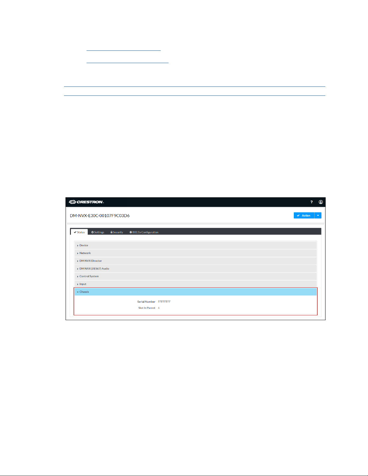
DMF-CI-8 Chassis Details
NOTE: DMF-CI-8 chassis details apply to the DM-NVX-E30C and DM-NVX-D30C only.
A DM NVX card occupies a DMF-CI-8 chassis. Information about the chassis can be
viewed using the web interface or SIMPL Windows.
Using the Web Interface
To view DMF-CI-8 chassis information, click the Status tab and then click Chassis.
The Chassis section displays the following information:
•Serial number of the chassis
•Number of the slot into which the card is installed
Status Tab – Chassis
Using SIMPL Windows
Using the top-level programming slot for the DM NVX card, program the
<ChassisSerialNumber_F>serial output join to report the serial number of the chassis in
which the card is installed. Program the <CardSlotInfo_F> serial output join to report the
slot number in which the card is installed in the chassis.
10 •DM-NVX-E30(C)/DM-NVX-D30(C)/DM-NVX-D80-IOAV Product Manual – DOC. 8425D
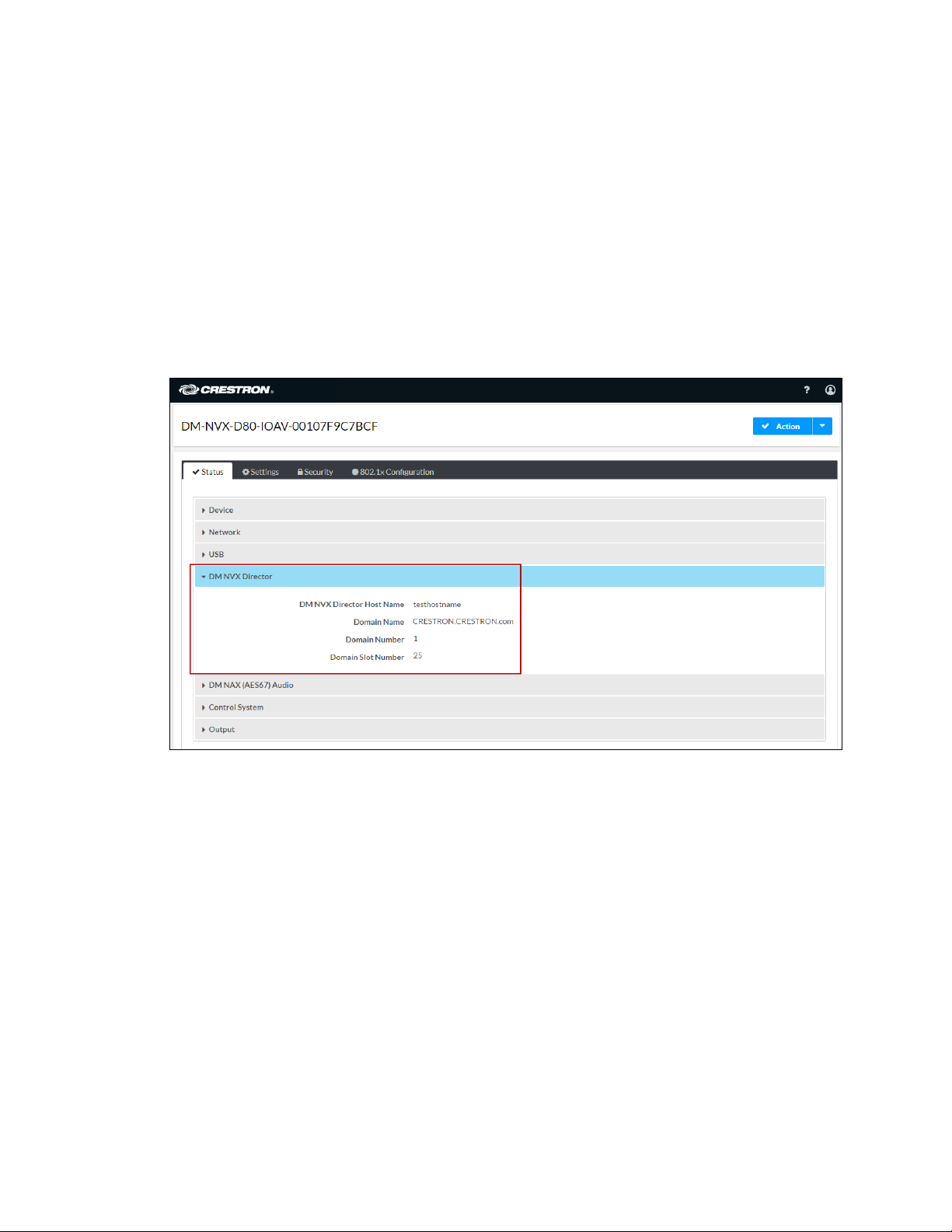
DM NVX Director Virtual Switching Appliance
If a DM NVX device is managed by a DM NVX Director™ virtual switching appliance,
information about the appliance can be viewed using the web interface.
To view DM NVX Director appliance information, click the Status tab and then click
DM NVX Director.
The DM NVX Director section displays the following information:
•DM NVX Director hostname
•Domain name, number, and slot number to which the DM NVX device is assigned
Status Tab – DM NVX Director

Product Manual – DOC. 8425D DM-NVX-E30(C)/DM-NVX-D30(C)/DM-NVX-D80-IOAV •11
Crestron XiO Cloud Service Connection
The Crestron XiO Cloud® service enables supported Crestron devices across an
enterprise to be managed and configured from one central and secure location in the
cloud. Connection to the Crestron XiO Cloud service can be enabled or disabled using the
web interface.
To configure the connection to the Crestron XiO Cloud service:
1. Click the Settings tab and then click System Setup.
2. In the Cloud Settings section, set the Cloud Configuration Service Connection
toggle switch in the On (right) or Off (left) position. The default setting is in the
On position.
Settings Tab – System Setup, Cloud Settings
For instructions about connecting to the service, refer to the DM-NVX-E30/DM-NVX-
D30 Quick Start (Doc. 8211), DM-NVX-E30C/DM-NVX-D30C Quick Start (Doc. 8346), or
DM-NVX-D80-IOAV Quick Start (Doc. 8526) as appropriate. For information about
using the service, refer to the XiO Cloud Provisioning and Management Service User
Guide (Doc. 8214).

12 •DM-NVX-E30(C)/DM-NVX-D30(C)/DM-NVX-D80-IOAV Product Manual – DOC. 8425D
Fan Control
NOTE: Fan control is applicable to the DM-NVX-D30 and DM-NVX-D80-IOAV.
Configure fan control or view fan status using the web interface or SIMPL Windows.
Using the Web Interface
To configure fan control:
1. Click the Settings tab and then click System Setup.
2. In the Fan Control section, set Fan Mode to one of the following:
•Auto: (Default setting) The fan automatically turns off when the following
two conditions exist:
1. No video stream is present.
2. The internal temperature of the device does not exceed the normal
operating range.
•Always On: The fan runs continuously regardless of video stream status and
internal temperature of the device.
Fan status is indicated as either of the following:
•Full On: The fan is running.
•Off: The fan is not running.
Settings Tab – System Setup, Fan Control

Product Manual – DOC. 8425D DM-NVX-E30(C)/DM-NVX-D30(C)/DM-NVX-D80-IOAV •13
Using SIMPL Windows
Using the top-level programming slot for the DM-NVX-D30, set the <FanControl>
analog input join to the desired setting. The <FanControl_F> analog output join reports
the fan mode of operation. The <FanStatus_F> analog output join reports the fan
status. For additional information, refer to the SIMPL Windows help file.
Automatic Point-to-Point Connectivity
Point-to-point connectivity enables a DM NVX encoder to be connected directly to a
DM NVX decoder to stream video, audio, and, if applicable, USB signals. Rather than
being connected to an Ethernet switch, a 1000BASE-T Ethernet port of an encoder is
connected directly to a 1000BASE-T port of a decoder. By default, point-to-point mode
is enabled (set to Auto) and can be disabled if desired. When enabled, no additional
configuration is required for the encoder or decoder to operate in point-to-point mode.
To enable or disable point-to-point mode, use the web interface or SIMPL Windows as
discussed in the following sections.
Using the Web Interface
Enable or disable point-to-point mode by clicking the Settings tab and then clicking
System Setup.
In the Point-to-Point Control section, Point to Point Status indicates whether point-to-
point mode is Active or Inactive.
In the Point-to-Point Mode drop-down list, select either of the following:
•Auto: (Default setting) A 1000BASE-T port of a DM NVX encoder detects a
direct connection to a DM NVX decoder or a connection to a 1000BASE-T switch.
Similarly, a 1000BASE-T port of a DM NVX decoder detects a direct connection
to a DM NVX encoder or a connection to a 1000BASE-T switch. If a direct
connection between an encoder and decoder is detected, point-to-point mode is
automatically enabled.
•Disable: Disables point-to-point mode

14 •DM-NVX-E30(C)/DM-NVX-D30(C)/DM-NVX-D80-IOAV Product Manual – DOC. 8425D
Settings Tab - System Setup, Point-to-Point Control (DM-NVX-D80-IOAV Shown)
Using SIMPL Windows
Using the top-level programming slot for the DM-NVX device, set the
<PointToPointMode> analog input join to the desired value. For additional information,
refer to the SIMPL Windows help file.
Stream Statistics
Statistics can be displayed to indicate the number of packets received or transmitted,
the number of dropped packets, and the bit rate of the received stream.
NOTE: The bit rate of the stream is displayed for the DM-NVX-D30, DM-NVX-D30C, and
DM-NVX-D80-IOAV only.
To enable or disable or to reset stream statistics, use the web interface or SIMPL
Windows as discussed in the following sections.
Using the Web Interface
To enable, disable, or reset stream statistics:
1. Click the Settings tab and then click Stream.
2. In the Advanced section:
•To enable or disable Statistics, set the Statistics toggle switch in the On
(right) or Off (left) position, respectively. The default setting is in the Off
(left) position.
•To reset statistics, click Reset Statistics.
For additional information, refer to the online help of the web interface.

Product Manual – DOC. 8425D DM-NVX-E30(C)/DM-NVX-D30(C)/DM-NVX-D80-IOAV •15
Settings Tab – Stream, Advanced, Statistics
Using SIMPL Windows
For the DM-NVX-E30 and DM-NVX-E30C, configure stream statistics in Slot-01: Stream
Transmit. For the DM-NVX-D30, DM-NVX-D30C, and DM-NVX-D80-IOAV, configure
stream statistics in Slot-02: Stream Receive. Trigger the <StatisticsEnabled>digital
input join to enable the reporting of statistics. To disable statistics, trigger the
<StatisticsDisabled>digital input join. To clear the statistics, trigger the
<ResetStatistics> digital input join. The corresponding serial joins are updated when the
digital input joins are triggered. For additional information, refer to the SIMPL Windows
help file.
Image Preview
NOTE: Image preview functionality is applicable to the DM-NVX-E30, DM-NVX-E30C,
DM-NVX-D30, and DM-NVX-D30C.
Image preview provides still images (thumbnails) that show the current video being
received by an input of a DM NVX transmitter or displayed by an output of a DM NVX
receiver. Still images are shown at one frame per second. Image preview supports the
maximum resolution of the source and scales the image, while maintaining the aspect
ratio. Images can be previewed in the DM NVX web interface and accessed remotely
using a web browser. The images can also be previewed on a Crestron touch screen or
third-party interface.
To configure image preview, use the web interface or SIMPL Windows as discussed in the
following sections.

16 •DM-NVX-E30(C)/DM-NVX-D30(C)/DM-NVX-D80-IOAV Product Manual – DOC. 8425D
Using the Web Interface
To configure image preview:
1. Click the Settingstab and then click Stream.
2. Under Services, enable Preview Output if it is disabled. The default setting is
Enabled. If video is present, video is displayed in the Preview window above
Services. (Double-clicking the Preview window displays the video window full
screen.)
3. Enter a base file name (prefix) to the file name of the images to be generated.
The default base file name is preview.
The Generated Preview Images table lists the image previews. Type indicates the
height of the image in pixels. File Name indicates the file name of the image in
the following format:
<base file name>_<vertical resolution>px.<extension>
•<base file name> is the prefix assigned to the image preview followed by
an underscore. If the default base file name of preview is changed, clicking
the table updates the base name in the table.
•<vertical resolution> is the height of the image in pixels (px).
•
<extension> is the file format of the image. The default file extension
is .jpeg.
For example, using the default base file name, which is preview, and a JPEG
image with a vertical resolution of 240 pixels, the file name of the image
preview is preview_240px.jpeg.
Local Preview Path indicates the /preview location to which image preview files
are saved to the web server of the DM NVX device. An image preview file can be
accessed from a web browser on a remote device by entering the following URL:
https://<username>:<password>@<ip address>/preview/<filename>
•<username> is the user name used to access the DM NVX web server
•<password> is the password used to access the DM NVX web server
•<ip address> is the IP address of the DM NVX device.
•<filename> is the file name of the image preview file.
For example:
https://admin:[email protected]0.160.90/preview/preview_540px.jpeg
•admin is the user name used to access the DM NVX web server
•admin is the password used to access the DM NVX web server
•172.30.160.90 is the IP address of the DM NVX device
•preview_540px.jpeg is the file name of the image preview file
This manual suits for next models
4
Table of contents
Other Crestron Electronics Media Converter manuals


Popular Media Converter manuals by other brands

MicroE Systems
MicroE Systems Dual Axis Averager Mercury 3000Si Installation and reference manual

Convergent Design
Convergent Design HD-Connect LE user manual

TR-Electronic
TR-Electronic LP-38 user manual

HP
HP 5254C Operating and service manual

Cabletron Systems
Cabletron Systems EMC38-12 user guide

LevelOne
LevelOne Infinity IEC-2001 Quick installation guide


