Crestron Electronics DM NVX Series User manual

DM NVX® Network AV
Encoders/Decoders
DM-NVX-350
DM-NVX-351
DM-NVX-352
DM-NVX-350C
DM-NVX-351C
DM-NVX-352C
Product Manual
Crestron Electronics, Inc.

Original Instructions
The U.S. English version of this document is the original instructions.
All other languages are a translation of the original instructions.
The product warranty can be found at www.crestron.com/legal/sales-terms-conditions-warranties.
The specific patents that cover Crestron products are listed at www.crestron.com/legal/patents.
Certain Crestron products contain open source software. For specific information, visit
www.crestron.com/legal/open-source-software.
Crestron, the Crestron logo, 3-Series, Crestron Toolbox, DigitalMedia, DM NAX, DM NVX, DM NVX Director, and XiO Cloud
are either trademarks or registered trademarks of Crestron Electronics, Inc. in the United States and/or other countries.
Audinate and Dante are either trademarks or registered trademarks of Audinate Pty Ltd. in the United States and/or other
countries. Dolby and Dolby Atmos are either trademarks or registered trademarks of Dolby Laboratories in the United
States and/or other countries. DTS HD and DTS:X are either trademarks or registered trademarks of DTS, Inc. in the United
States and/or other countries. HDMI and the HDMI logo are either trademarks or registered trademarks of HDMI Licensing
LLC in the United States and/or other countries. Active Directory is either a trademark or registered trademark of Microsoft
Corporation in the United States and/or other countries. DisplayPort is either a trademark or registered trademark of Video
Electronics Standards Association in the United States and/or other countries. Other trademarks, registered trademarks,
and trade names may be used in this document to refer to either the entities claiming the marks and names or their
products. Crestron disclaims any proprietary interest in the marks and names of others. Crestron is not responsible for errors
in typography or photography.
©2021 Crestron Electronics, Inc.

Product Manual – DOC. 7839L Contents •i
Contents
Introduction.................................................................................................................................... 1
Physical Description......................................................................................................................2
DM-NVX-350, DM-NVX-351, and DM-NVX-352 .................................................................................. 2
Front Panel, DM-NVX-350 and DM-NVX-351 ............................................................................... 2
Front Panel, DM-NVX-352.................................................................................................................4
Rear Panel.............................................................................................................................................5
DM-NVX-350C and DM-NVX-351C........................................................................................................ 7
DM-NVX-352C ............................................................................................................................................8
Configuration and Status......................................................................................................... 10
DMF-CI-8 Chassis Details....................................................................................................................... 11
Using the Web Interface...................................................................................................................11
Using SIMPL Windows ......................................................................................................................11
DM NVX Director Virtual Switching Appliance.................................................................................. 12
Encoding and Decoding Functionality ................................................................................................. 12
Using the Web Interface.................................................................................................................. 13
Using SIMPL Windows ..................................................................................................................... 14
Automatic Point-to-Point Connectivity .............................................................................................. 14
Using the Web Interface.................................................................................................................. 15
Using SIMPL Windows ..................................................................................................................... 15
Stream Statistics..................................................................................................................................... 16
Using the Web Interface.................................................................................................................. 16
Using SIMPL Windows ..................................................................................................................... 16
Multicast TTL (Time-to-Live)................................................................................................................. 17
Using the Web Interface.................................................................................................................. 17
Using SIMPL Windows ..................................................................................................................... 18
Differentiated Services Code Point (DSCP) ...................................................................................... 19
Automatic Routing of Video Inputs..................................................................................................... 20
Using the Web Interface................................................................................................................. 20
Using SIMPL Windows ..................................................................................................................... 21
Automatic Display Control .................................................................................................................... 22
Video Wall Processing .............................................................................................................................25
Using the Web Interface..................................................................................................................25
Using SIMPL Windows ..................................................................................................................... 27
Adjustable Underscan .............................................................................................................................27
Using the Web Interface.................................................................................................................. 27
Using SIMPL Windows .....................................................................................................................28
User-Selectable Output Resolution .....................................................................................................29
Using the Web Interface..................................................................................................................29
Using SIMPL Windows .................................................................................................................... 30
Maximum Color Depth and Color Space Mode ................................................................................. 31
Using the Web Interface.................................................................................................................. 31
Using SIMPL Windows .....................................................................................................................33
EDID (Extended Display Identification Data)....................................................................................33

ii •Contents Product Manual – DOC. 7839L
Adaptive Bit Rate.....................................................................................................................................36
Using the Web Interface..................................................................................................................36
Using SIMPL Windows .....................................................................................................................37
Subscriptions ............................................................................................................................................37
Using the Web Interface..................................................................................................................38
Using SIMPL Windows .....................................................................................................................39
Daisy Chain .............................................................................................................................................. 40
Switching Subscribed Transmitters ............................................................................................. 40
Switching Nonsubscribed Transmitters ....................................................................................... 41
7.1 Surround Sound Audio ......................................................................................................................42
DM NAX Audio over IP (AES67) ............................................................................................................42
Using the Web Interface..................................................................................................................43
Using SIMPL Windows .....................................................................................................................47
Dante and AES67 Audio Embedding and De-embedding .............................................................. 48
Using the Web Interface..................................................................................................................49
Using SIMPL Windows .................................................................................................................... 50
Analog Audio Input or Output............................................................................................................... 51
Using the Web Interface.................................................................................................................. 51
Using SIMPL Windows .....................................................................................................................54
Breakaway Audio .....................................................................................................................................54
Using the Web Interface..................................................................................................................54
Using SIMPL Windows .....................................................................................................................55
USB 2.0 Routing .......................................................................................................................................56
Using the Web Interface..................................................................................................................56
Using SIMPL Windows .....................................................................................................................59
Network Port Selection........................................................................................................................... 61
Device Mode Locking...............................................................................................................................62
Crestron XiO Cloud Service Connection .............................................................................................63
Enterprise-Grade Security .....................................................................................................................64
Authentication Management .........................................................................................................64
IEEE 802.1X Authentication ............................................................................................................65
Automatic Firmware Update ................................................................................................................67
IGMP Snooping........................................................................................................................... 69
Troubleshooting.......................................................................................................................... 72
Appendix. Device Discovery ...................................................................................................... 75

Product Manual – DOC. 7839L DM-NVX-35x(C) Encoders/Decoders •1
Introduction
Crestron® DM NVX® network AV encoders/decoders transport ultra high-definition
4K video with 60 Hz frame rates and 4:4:4 color sampling over standard Gigabit
Ethernet. Support for High Dynamic Range (HDR) video and HDCP 2.2 ensures high
picture quality and compatibility with a variety of media sources. Using Pixel Perfect
Processing technology, a video signal is encoded and then decoded to achieve
imperceptible end-to-end latency of less than 1 frame.
DM-NVX-35x(C) encoders/decoders consist of the following:
•Surface-mountable endpoints: DM-NVX-350, DM-NVX-351, and DM-NVX-352.
Compact in design, the endpoints are designed to fit in various locations, for
example, behind a flat panel display.
•Card endpoints: DM-NVX-350C, DM-NVX-351C, and DM-NVX-352C. The cards
are designed to occupy the DMF-CI-8 card chassis.
The DM-NVX-351 and DM-NVX-351C provide the same functionality as the
DM-NVX-350 and DM-NVX-350C with the addition of surround sound to stereo
downmixing. The DM-NVX-352 and DM-NVX-352C provide the same functionality as the
DM-NVX-350 and DM-NVX-350C with the addition of Dante® audio networking.
All DM-NVX-35x(C) devices offer encoding and decoding capabilities in a single unit.
NOTE: DM-NVX-35x(C) encoders/decoders are compatible with DM-NVX-36x(C)
encoders/decoders, DM-NVX-E30(C) encoders, DM-NVX-D30(C) decoders, and
DM-NVX-D80-IOAV decoders. Scaling is supported by DM-NVX-35x(C) and
DM-NVX-36x(C) decoders only.
This manual provides information about the following:
•Physical description
•Configuration and status
•IGMP snooping
•Troubleshooting
In addition, information about device discovery of a DM NVX device using Crestron
Toolbox™ software is provided in the appendix of this manual.
For DM-NVX-35x(C) installation information, refer to the following documents as
applicable:
•DM-NVX-350, DM-NVX-351, and DM-NVX-352 Quick Start (Doc. 8391)
•DM-NVX-350C, DM-NVX-351C, and DM-NVX-352C Quick Start (Doc. 8392)
For information about designing a DM NVX system, refer to the DM NVX AV-over-IP
System Design Guide (Doc. 7977).

2 •DM-NVX-35x(C) Encoders/Decoders Product Manual – DOC. 7839L
Physical Description
The following sections provide information about the connectors, controls, and indicators
that are available on DM-NVX-35x(C) devices.
DM-NVX-350, DM-NVX-351, and DM-NVX-352
This section provides information about the front and rear panels of the DM-NVX-350,
DM-NVX-351, and DM-NVX-352.
Front Panel, DM-NVX-350 and DM-NVX-351
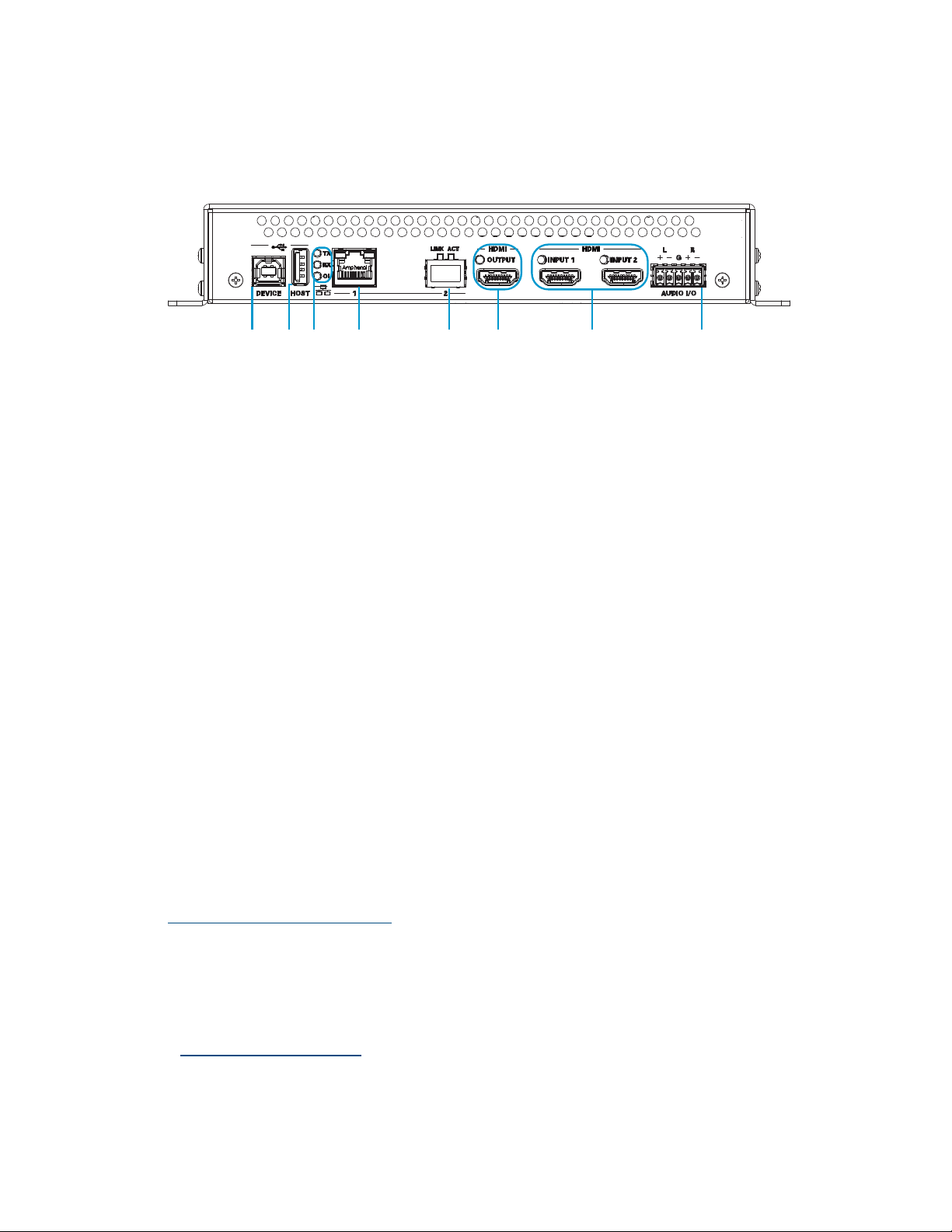
The following illustration shows the front panel of the DM-NVX-350 and DM-NVX-351.
DM-NVX-350 and DM-NVX-351 Front Panel
DEVICE: USB Type B connector, female;
USB 2.0 device port;
USB signal extender port for connection to a computer or other USB 2.0 host*
HOST: USB Type A connector, female;
USB 2.0 host port;
USB signal extender port for connection of a mouse, keyboard, or any other
USB 2.0 device;*
Available Power: 500 mA at 5 VDC
TX, RX, and OL LEDs: Green TX LED indicates that the device is in transmitter
(encoder) mode;
Green RX LED indicates that the device is in receiver (decoder) mode;
Green OL LED indicates an online connection to a control system via Ethernet
* The DEVICE and HOST ports cannot be used simultaneously.

Product Manual – DOC. 7839L DM-NVX-35x(C) Encoders/Decoders •3
LAN 1: 8-pin RJ-45 connector, female;
100BASE-TX/1000BASE-T Ethernet port;1
PD (powered device) port compatible with UPOE compliant Ethernet switch,
Crestron DM-PSU-ULTRA-MIDSPAN, or approved third-party PSE;2
Green LED indicates Ethernet link status;
Amber LED indicates Ethernet activity
LAN 2: 8-pin RJ-45 connector, female;
100BASE-TX/1000BASE-T Ethernet port;1
Green LED indicates Ethernet link status;
Amber LED indicates Ethernet activity
LAN 3: SFP port;
Accepts one Crestron SFP-1G Series SFP transceiver module;3
Green LINK LED indicates Ethernet link status;
Green ACT LED indicates Ethernet activity
HDMI OUTPUT: 19-pin HDMI® Type A connector, female;
HDMI digital video/audio output (DVI compatible);4,5
Green LED indicates video signal transmission at the HDMI output
HDMI INPUTS 1–2: 19-pin HDMI Type A connectors, female;
HDMI digital video/audio inputs (DVI and Dual-Mode DisplayPort™ compatible);4, 5
Two green LEDs, each indicates sync detection at the corresponding HDMI input
AUDIO I/O: 5-pin 3.5 mm detachable terminal block;
Balanced/unbalanced stereo line-level audio input or output;
Input Impedance: 24k Ohms balanced/unbalanced;
Maximum Input Level: 4 Vrms balanced, 2 Vrms unbalanced;
Output Impedance: 200 Ohms balanced, 100 Ohms unbalanced;
Maximum Output Level: 4 Vrms balanced, 2 Vrms unbalanced
1Either LAN 1 or LAN 2 can be used as the primary LAN connection, allowing the other port to be used for
connection to a local network device or to another DM NVX device. If one of the ports is used as the primary
LAN connection, the port requires connection to a 1000BASE-T switch in order to stream network video.
2The DM-NVX-350 and DM-NVX-351 can be powered by the connection of LAN 1 to a UPOE compliant
Ethernet switch, a Crestron DM-PSU-ULTRA-MIDSPAN, or other Crestron approved power injector (sold
separately). For additional information, refer to Answer ID 5791 in the Online Help section of the Crestron
website (www.crestron.com/onlinehelp). The DM-NVX-350 and DM-NVX-351 can also be powered using the
included power pack.
3LAN 3 can be used as the primary LAN connection or can be connected to another DM NVX device. LAN 3 can
connect to a fiber-optic network using the appropriate Crestron SFP-1G transceiver module (sold separately).
Refer to the SFP-1G Series Installation Guide (Doc. 7979) for information about installing Crestron SFP-1G
Series transceiver modules.
4HDMI connections require an appropriate adapter or interface cable to accommodate a DVI or Dual-Mode
DisplayPort signal. CBL-HD-DVI interface cables are sold separately.
5Device control via CEC requires the use of a Crestron 3-Series® or later control system.
4 •DM-NVX-35x(C) Encoders/Decoders Product Manual – DOC. 7839L
Front Panel, DM-NVX-352
The following illustration shows the front panel of the DM-NVX-352.
DM-NVX-352 Front Panel
DEVICE: USB Type B connector, female;
USB 2.0 device port;
USB signal extender port for connection to a computer or other USB 2.0 host1
HOST: USB Type A connector, female;
USB 2.0 host port;
USB signal extender port for connection of a mouse, keyboard, or any other
USB 2.0 device;1
Available Power: 500 mA at 5 VDC
TX, RX, and OL LEDs: Green TX LED indicates that unit is in transmitter (encoder)
mode;
Green RX LED indicates that unit is in receiver (decoder) mode;
Green OL LED indicates an online connection to a control system via Ethernet
LAN 1: 8-pin RJ-45 connector, female;
100BASE-TX/1000BASE-T Ethernet port;2
PD (powered device) port compatible with UPOE compliant Ethernet switch,
Crestron DM-PSU-ULTRA-MIDSPAN, or approved third-party PSE;3
Green LED indicates Ethernet link status;
Amber LED indicates Ethernet activity
LAN 2: SFP port;
Accepts one Crestron SFP-1G Series SFP transceiver module; 2, 4
Green LINK LED indicates Ethernet link status;
Green ACT LED indicates Ethernet activity
1The DEVICE and HOST ports cannot be used simultaneously.
2Either LAN 1 or LAN 2 can be used as the primary LAN connection, allowing the other port to be used for
connection to a local network device or to another DM NVX device. The port that is used as the primary
LAN connection requires connection to a 1000BASE-T switch in order to stream network video.
3The DM-NVX-352 can be powered by the connection of LAN 1 to a UPOE compliant Ethernet switch, a
Crestron DM-PSU-ULTRA-MIDSPAN, or other Crestron approved power injector (sold separately).
For additional information, refer to Answer ID 5791 in the Online Help section of the Crestron website
(www.crestron.com/onlinehelp). The DM-NVX-352 can also be powered using the included
power pack.
4LAN 3 can connect to a fiber-optic network using the appropriate Crestron SFP-1G transceiver module (sold
separately). Refer to the SFP-1G Series Installation Guide (Doc. 7979) for information about installing
Crestron SFP-1G Series transceiver modules.

Product Manual – DOC. 7839L DM-NVX-35x(C) Encoders/Decoders •5
HDMI OUTPUT: 19-pin HDMI Type A connector, female;
HDMI digital video/audio output (DVI compatible);1, 2
Green LED indicates video signal transmission at the HDMI output
HDMI INPUTS 1–2: 19-pin HDMI Type A connectors, female;
HDMI digital video/audio inputs (DVI and Dual-Mode DisplayPort compatible);1, 2
Two green LEDs, each indicates sync detection at the corresponding HDMI input
AUDIO I/O: 5-pin 3.5 mm detachable terminal block;
Balanced/unbalanced stereo line-level audio input or output;
Input Impedance: 24k Ohms balanced/unbalanced;
Maximum Input Level: 4 Vrms balanced, 2 Vrms unbalanced;
Output Impedance: 200 Ohms balanced, 100 Ohms unbalanced;
Maximum Output Level: 4 Vrms balanced, 2 Vrms unbalanced
Rear Panel
The following illustration shows the rear panel of the DM-NVX-350, DM-NVX-351, and
DM-NVX-352.
DM-NVX-350, DM-NVX-351, and DM-NVX-352 Rear Panel
CONSOLE, SERIAL: 8-pin RJ-45 connector, female;
RS-232 computer console port for setup
CONSOLE, USB: USB Type B connector, female;
USB 2.0 computer console port for setup
PWR: Bicolor green/amber LED, indicates operating power supplied via the power
pack (included), UPOE compliant Ethernet switch, or injector/PSE, lights amber while
booting and green when operating
SETUP: Recessed push button for on-screen IP address display and to change the
operating mode (transmitter or receiver). Red LED indicates that the SETUP button
is pressed and times out automatically.
1HDMI connections require an appropriate adapter or interface cable to accommodate a DVI or Dual-Mode
DisplayPort signal. CBL-HD-DVI interface cables are sold separately.
2Device control via CEC requires the use of a Crestron 3-Series® or later control system.

6•DM-NVX-35x(C) Encoders/Decoders Product Manual – DOC. 7839L
NOTES:
•When a DM-NVX-35x decoder is connected to a DM-NVX-35x(C), DM-NVX-
36x(C), or DM-NVX-E30(C) encoder, pressing the SETUP button on the decoder
for less than 10 seconds displays the decoder IP address on the display connected
to the HDMI output of the decoder.
•When a DM-NVX-35x encoder is connected to a DM-NVX-35x(C) decoder,
pressing the SETUP button on the encoder for less than 10 seconds displays the
encoder IP address on the display connected to the HDMI output of the encoder.
In addition, the decoder IP address is shown on the display connected to the
HDMI output of the decoder.
•When a DM-NVX-35x encoder is connected to a DM-NVX-36x(C), DM-NVX-
D30(C) or DM-NVX-D80-IOAV decoder, pressing the SETUP button on the
encoder for less than 10 seconds displays the encoder IP address on the display
connected to the HDMI output of the encoder. Both encoder and decoder IP
addresses are shown on the display connected to the HDMI output of the
decoder.
•When the SETUP button is pressed for 10 seconds, a message appears on the
display stating that the button must be pressed again to change the operating
mode. Pressing the button a second time changes the operating mode from a
receiver (decoder) to a transmitter (encoder) or from a transmitter to a receiver
and reboots the device.
The SETUP button can be used to change the operating mode only if Device
Mode Lock is disabled in the System Setup section under the Settings tab.
For additional information, refer to "Device Mode Locking" on page 62.
RESET: Recessed push button for hardware reset
INPUT SEL: Push button for manual input selection and two bicolor green/amber
LEDs. Green LED indicates that the corresponding input is selected. Amber LED
indicates that the corresponding input is detected but is not selected.
IR 1–2: 4-pin 3.5 mm detachable terminal block;
Comprises two IR/serial ports;∗
IR output up to 1.1 MHz;
1-way serial TTL/RS-232 (0–5 volts) up to 19200 baud;
Crestron IRP2 emitter sold separately
COM: 5-pin 3.5 mm detachable terminal block;
Bidirectional RS-232 port;*
Up to 115.2k baud, hardware and software handshaking support
24VDC 2.0A: 2.1 x 5.5 mm DC power connector;
24 VDC power input;
Power pack included
Ground: 6-32 screw, chassis ground lug
∗Device control via IR and RS-232 requires integration with a Crestron 3-Series or later control system.
Product Manual – DOC. 7839L DM-NVX-35x(C) Encoders/Decoders •7
DM-NVX-350C and DM-NVX-351C
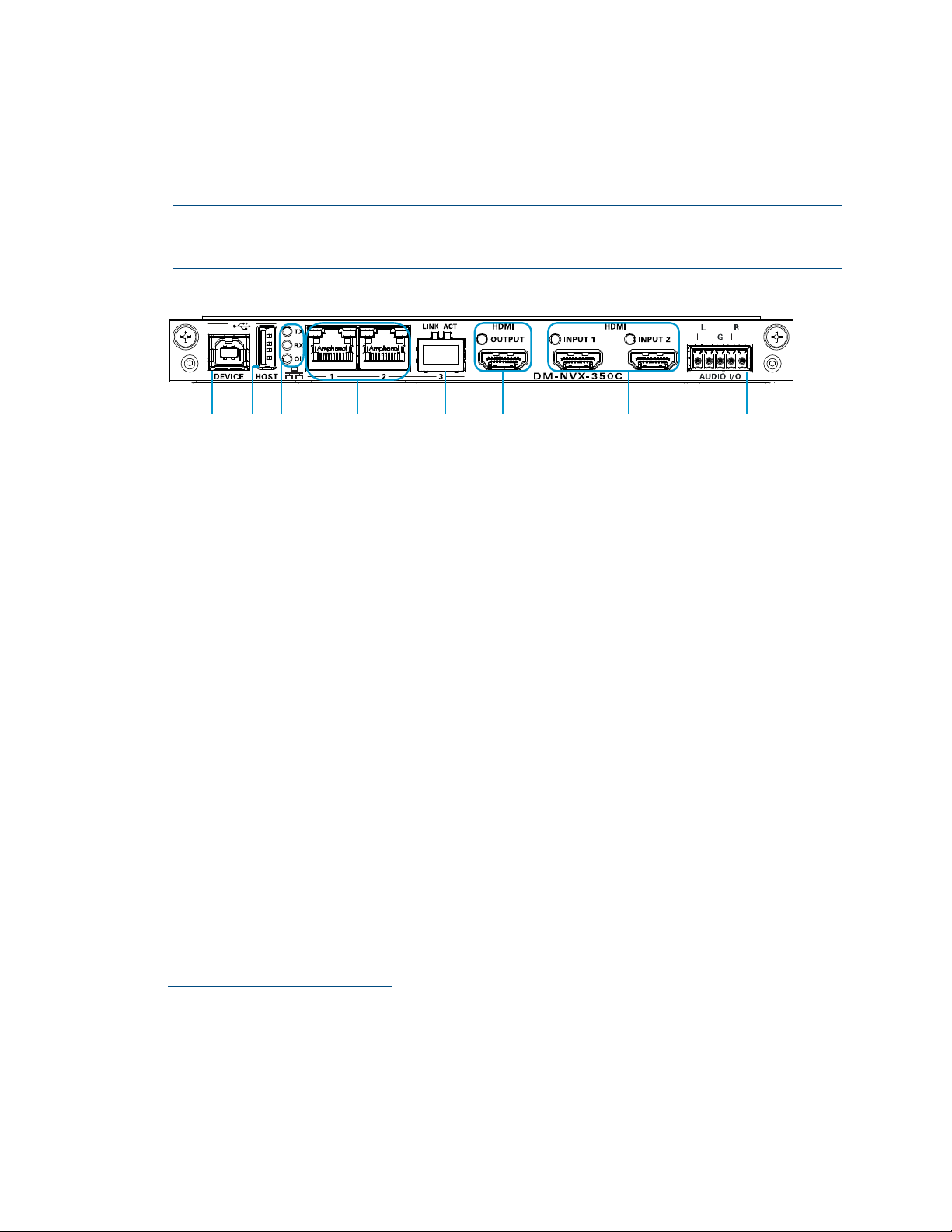
The following illustration shows the connectors, controls, and indicators that are
available on the DM-NVX-350C and DM-NVX-351C.
NOTE: The DM-NVX-350C and DM-NVX-351C contain the same connectors, controls,
and indicators. For illustrative purposes, only the card named DM-NVX-350C is
shown below.
DM-NVX-350C
DEVICE: USB Type B connector, female;
USB 2.0 device port;
USB signal extender port for connection to a computer or any other USB 2.0 host1
HOST: USB Type A connector, female;
USB 2.0 host port;
USB signal extender port for connection of a mouse, keyboard, or any other
USB 2.0 device;1
Available Power: 500 mA at 5 VDC
TX, RX, and OL LEDs: Green TX LED indicates that unit is in transmitter (encoder)
mode;
Green RX LED indicates that unit is in receiver (decoder) mode;
Green OL LED indicates an online connection to a control system via Ethernet
LAN 1–2: 8-pin RJ-45 connectors, female;
100BASE-TX/1000BASE-T Ethernet ports2
Green LED indicates Ethernet link status;
Amber LED indicates Ethernet activity
LAN 3: SFP port;2
Accepts one Crestron SFP-1G Series SFP transceiver module;3
Green LINK LED indicates Ethernet link status;
Green ACT LED indicates Ethernet activity
1The DEVICE and HOST ports cannot be used simultaneously.
2Either LAN 1 or LAN 2 can be used as the primary LAN connection, allowing the other port to be used for
connection to a local network device or to another DM NVX device. If one of the ports is used as the primary
LAN connection, the port requires connection to a 1000BASE-T switch in order to stream network video.
3LAN 3 can be used as the primary LAN connection or can be connected to another DM NVX device. LAN 3 can
connect to a fiber-optic network using the appropriate Crestron SFP-1G transceiver module (sold separately).
Refer to the SFP-1G Series Installation Guide (Doc. 7979) for information about installing Crestron SFP-1G
Series transceiver modules.
8 •DM-NVX-35x(C) Encoders/Decoders Product Manual – DOC. 7839L
HDMI OUTPUT: 19-pin HDMI Type A connector, female;
HDMI digital video/audio output (DVI compatible)1, 2
Green LED indicates video signal transmission at the HDMI output
HDMI INPUTS 1–2: 19-pin HDMI Type A connectors, female;
HDMI digital video/audio inputs (DVI and Dual-Mode DisplayPort compatible)1, 2
Two green LEDs, each indicates sync detection at the corresponding HDMI input
AUDIO I/O: 5-pin 3.5 mm detachable terminal block;
Balanced/unbalanced stereo line-level audio input or output;
Input Impedance: 24k Ohms balanced/unbalanced;
Maximum Input Level: 4 Vrms balanced, 2 Vrms unbalanced;
Output Impedance: 200 Ohms balanced, 100 Ohms unbalanced;
Maximum Output Level: 4 Vrms balanced, 2 Vrms unbalanced
DM-NVX-352C
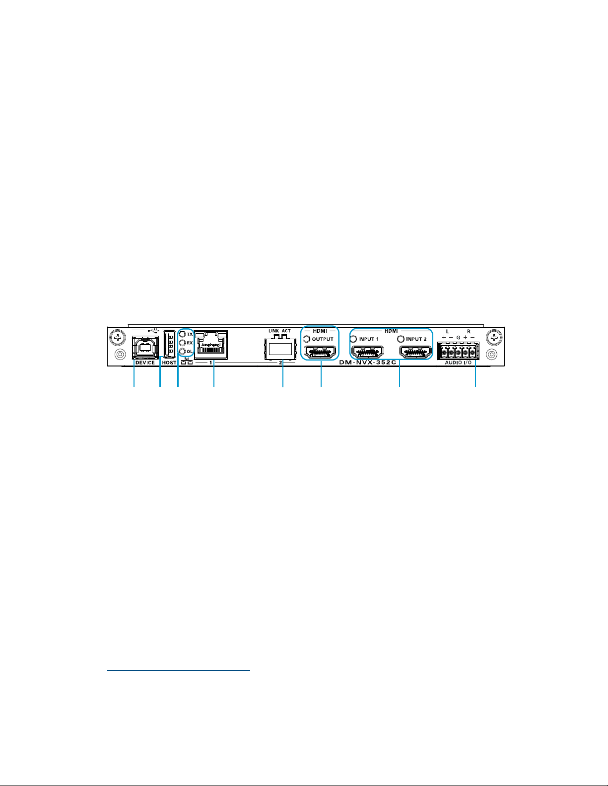
The following illustration shows the connectors, controls, and indicators that are
available on the DM-NVX-352C.
DM-NVX-352C
DEVICE: USB Type B connector, female;
USB 2.0 device port;
USB signal extender port for connection to a computer or any other USB 2.0 host3
HOST: USB Type A connector, female;
USB 2.0 host port;
USB signal extender port for connection of a mouse, keyboard, or any other
USB 2.0 device;3
Available Power: 500 mA at 5 VDC
TX, RX, and OL LEDs: Green TX LED indicates that unit is in transmitter (encoder)
mode;
Green RX LED indicates that unit is in receiver (decoder) mode;
Green OL LED indicates an online connection to a control system via Ethernet
1HDMI connections require an appropriate adapter or interface cable to accommodate a DVI or Dual-Mode
DisplayPort signal. CBL-HD-DVI interface cables are sold separately.
2Device control via CEC requires integration with a Crestron 3-Series or later control system.
3The DEVICE and HOST ports cannot be used simultaneously.

Product Manual – DOC. 7839L DM-NVX-35x(C) Encoders/Decoders •9
LAN 1: 8-pin RJ-45 connector, female;
100BASE-TX/1000BASE-T Ethernet port;1
Green LED indicates Ethernet link status;
Amber LED indicates Ethernet activity
LAN 2:SFP port;
Accepts one Crestron SFP-1G Series SFP transceiver module;1, 2
Green LINK LED indicates Ethernet link status;
Green ACT LED indicates Ethernet activity
HDMI OUTPUT: 19-pin HDMI Type A connector, female;
HDMI digital video/audio output (DVI compatible)3, 4
HDMI INPUTS 1–2: 19-pin HDMI Type A connector, female;
HDMI digital video/audio inputs (DVI and Dual-Mode DisplayPort compatible)3, 4
Two green LEDs, each indicates sync detection at the corresponding HDMI input
AUDIO I/O: 5-pin 3.5 mm detachable terminal block;
Balanced/unbalanced stereo line-level audio input or output;
Input Impedance: 24k Ohms balanced/unbalanced;
Maximum Input Level: 4 Vrms balanced, 2 Vrms unbalanced;
Output Impedance: 200 Ohms balanced, 100 Ohms unbalanced;
Maximum Output Level: 4 Vrms balanced, 2 Vrms unbalanced
1Either LAN 1 or LAN 2 can be used as the primary LAN connection, allowing the other port to be used for
connection to a local network device or to another DM NVX device. The port that is used as the primary
LAN connection requires connection to a 1000BASE-T switch in order to stream network video.
2LAN 2 can connect to a fiber-optic network using the appropriate Crestron SFP-1G transceiver module
(sold separately). Refer to the SFP-1G Series Installation Guide (Doc. 7979) for information about installing
Crestron SFP-1G Series transceiver modules.
3HDMI connections require an appropriate adapter or interface cable to accommodate a DVI or Dual-Mode
DisplayPort signal. CBL-HD-DVI interface cables are sold separately.
4Device control via CEC requires integration with a Crestron 3-Series or later control system.

10 •DM-NVX-35x(C) Encoders/Decoders Product Manual – DOC. 7839L
Configuration and Status
This section provides information about configuring or viewing the following items using
the web interface or SIMPL Windows as applicable:
•DMF-CI-8 chassis details
•DM NVX Director™ virtual switching appliance
•Encoding and decoding functionality
•Automatic point-to-point connectivity
•Stream statistics
•Multicast TTL (Time-to-Live)
•Differentiated Services Code Point (DSCP)
•Automatic routing of video inputs
•Automatic display control
•Video wall processing
•Adjustable underscan
•User-selectable output resolution
•Maximum color depth and color space mode
•EDID (Extended Display Identification Data)
•Adaptive bit rate
•Subscriptions
•Daisy chain
•7.1 surround sound audio
•DM NAX audio over IP (AES67)
•Dante and AES67 audio embedding and de-embedding
•Analog audio input or output
•Breakaway audio
•USB 2.0 routing
•Network port selection
•Device mode locking
•Crestron XiO Cloud service connection
•Enterprise-grade security
•Automatic firmware update
Product Manual – DOC. 7839L DM-NVX-35x(C) Encoders/Decoders •11
DMF-CI-8 Chassis Details
NOTE: DMF-CI-8 chassis details apply to the DM NVX cards only and do not apply to
DM NVX surface-mountable endpoints.
A DM NVX card occupies a card slot in a DMF-CI-8 chassis. Information about the
chassis can be viewed using the web interface or SIMPL Windows.
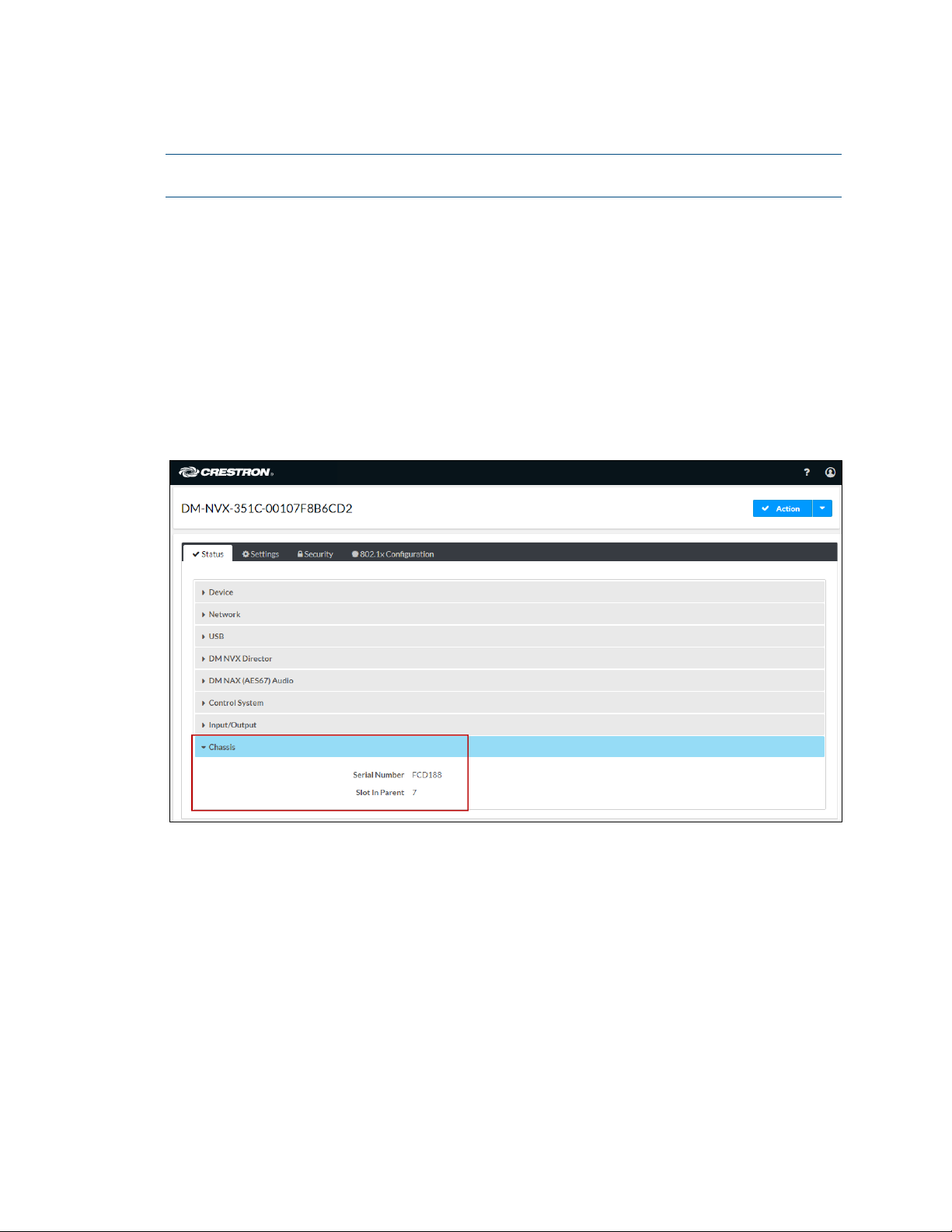
Using the Web Interface
To view DMF-CI-8 chassis information, click the Status tab and then click Chassis.
The Chassis section displays the following information:
•Serial number of the chassis
•Number of the slot into which the card is installed
Status Tab – Chassis
Using SIMPL Windows
Using the top-level programming slot for the DM NVX card, program the
<ChassisSerialNumber_F>serial output join to report the serial number of the chassis in
which the card is installed. Program the <CardSlotInfo_F> serial output join to report the
slot number in which the card is installed in the chassis.

12 •DM-NVX-35x(C) Encoders/Decoders Product Manual – DOC. 7839L
DM NVX Director Virtual Switching Appliance
If a DM NVX device is managed by a DM NVX Director™ virtual switching appliance,
information about the appliance can be viewed using the web interface.
To view DM NVX Director appliance information, click the Status tab and then click
DM NVX Director.
The DM NVX Director section displays the following information:
•DM NVX Director host name
•Domain name, number, and slot number to which the DM NVX device is assigned
Status Tab – DM NVX Director
Encoding and Decoding Functionality
A DM-NVX-35x(C) device can be configured to function as a network AV encoder
(transmitter) or decoder (receiver):
•As an encoder, a DM NVX device allows a laptop computer, camera, or other
media source to be connected via an HDMI cable and then transmitted over the
network.
•As a decoder, a DM NVX device receives the signal from a DM NVX encoder and
feeds the signal to a display device via the HDMI output. A DM NVX decoder can
switch streams among multiple DM NVX encoders on the network alongside
locally connected HDMI sources.
To set the operating mode of a DM-NVX-35x(C) device as a transmitter or receiver, use
the web interface or SIMPL Windows as discussed in the following sections.

Product Manual – DOC. 7839L DM-NVX-35x(C) Encoders/Decoders •13
NOTES:
•When DM-NVX-35x(C) devices are used with DM-NVX-E30(C) and DM-NVX-36x(C)
encoders, the DM-NVX-35x(C) devices must be in Receiver mode. When DM-NVX-
35x(C) devices are used with DM-NVX-D30(C), DM-NVX-D80-IOAV, and DM-NVX-
36x(C) decoders, the DM-NVX-35x(C) devices must be in Transmitter mode.
•For a DM-NVX-35x surface-mountable endpoint, the SETUP button can be used to
change the operating mode from a receiver to a transmitter or from a transmitter to
a receiver. For additional information, refer to the description of the SETUP button
on page 5.
For a DM-NVX-35xC card, the front panel of the DMF-CI-8 chassis can be used to
change the operating mode. For additional information, refer to the DMF-CI-8
Supplemental Guide (Doc. 7861).
Using the Web Interface
To set the DM-NVX-35x(C) operating mode:
1. Click the Settings tab and then click Stream.
2. In the Mode drop-down list, select Receiver or Transmitter. The default setting is
Receiver (decoder).
Settings Tab – Stream, Mode Configuration
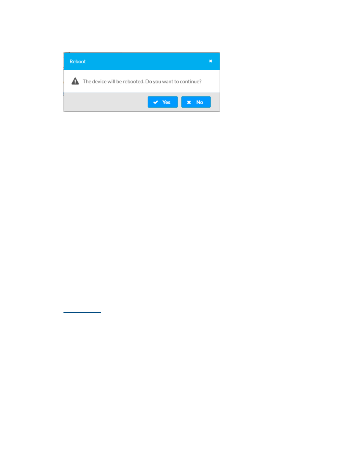
When a different mode is selected, a prompt appears asking for confirmation that the
device be rebooted. Click Yes to reboot the device.
14 •DM-NVX-35x(C) Encoders/Decoders Product Manual – DOC. 7839L
Device Reboot Prompt
For additional information, refer to the online help of the web interface.
Using SIMPL Windows
Using the top-level programming slot for the DM-NVX-35x(C) device, set the
<DeviceMode>analog input join to the desired mode (Receiver or Transmitter).
The default setting is Receiver.
Changing modes requires that the device be rebooted. Trigger the <Reboot> digital
input join to reboot the device. For additional information, refer to the SIMPL Windows
help file.
Automatic Point-to-Point Connectivity
Point-to-point connectivity enables a DM NVX encoder to be connected directly to a
DM NVX decoder to stream video, audio, and USB. Rather than being connected to an
Ethernet switch, a 1000BASE-T Ethernet port of an encoder is connected directly to a
1000BASE-T port of a decoder. By default, point-to-point mode is enabled (set to Auto)
and can be disabled if desired.
When point-to-point mode is enabled, no additional configuration is required for the
encoder or decoder to operate in point-to-point mode; however, the operating mode of a
DM-NVX-35x(C) device must be set correctly. If the device is to function as an encoder,
the operating mode must be set to Transmitter. If the device is to function as a decoder,
the operating mode must be set to Receiver. For information about setting the
operating mode of DM-NVX-35x(C) devices, refer to Encoding and Decoding
Functionality.
To enable or disable point-to-point mode, use the web interface or SIMPL Windows as
discussed in the following sections.
Product Manual – DOC. 7839L DM-NVX-35x(C) Encoders/Decoders •15
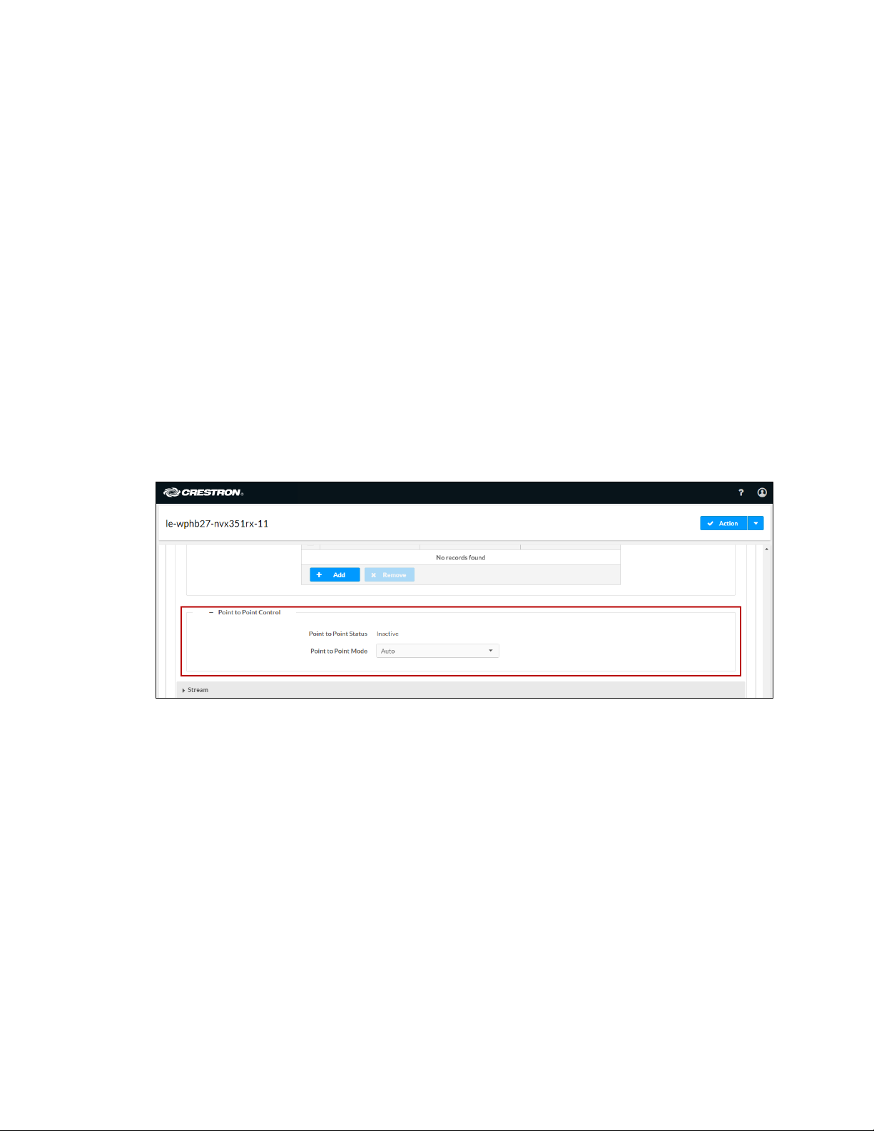
Using the Web Interface
Enable or disable point-to-point mode by clicking the Settings tab and then clicking
System Setup.
In the Point-to-Point Control section, Point to Point Status indicates whether point-to-
point mode is Active or Inactive.
In the Point-to-Point Modedrop-down list, select either of the following:
•Auto: (Default setting) A 1000BASE-T port of a DM NVX encoder detects a
direct connection to a DM NVX decoder or a connection to a 1000BASE-T switch.
Similarly, a 1000BASE-T port of a DM NVX decoder detects a direct connection
to a DM NVX encoder or a connection to a 1000BASE-T switch. If a direct
connection between an encoder and decoder is detected, point-to-point mode is
automatically enabled.
•Disable: Disables point-to-point mode
To enable or disable point-to-point mode, use the web interface or SIMPL Windows as
discussed in the following sections.
Settings Tab - System Setup, Point-to-Point Control
Using SIMPL Windows
Using the top-level programming slot for the DM-NVX-35x(C) device, set the
<PointToPointMode> analog input join to the desired value. For additional information,
refer to the SIMPL Windows help file.

16 •DM-NVX-35x(C) Encoders/Decoders Product Manual – DOC. 7839L
Stream Statistics
Statistics can be displayed to indicate the number of packets received or transmitted,
the number of dropped packets, and the bit rate of the received stream. To enable or
disable or to reset stream statistics, use the web interface or SIMPL Windows as
discussed in the following sections.
Using the Web Interface
To enable, disable, or reset stream statistics:
1. Click the Settings tab and then click Stream.
2. In the Advanced section:
•To enable or disable Statistics,set the Statistics toggle switch in the On
(right) or Off (left) position, respectively. The default setting is in the Off
(left) position.
•To reset statistics, click Reset Statistics.
For additional information, refer to the online help of the web interface.
Settings Tab – Stream, Statistics
Using SIMPL Windows
Configure stream statistics in Slot-01: Stream Transmit or Slot-02: Stream Receive.
Trigger the <StatisticsEnabled>digital input join to enable the reporting of statistics.
To disable statistics, trigger the <StatisticsDisabled>digital input join. To clear the
statistics, trigger the <ResetStatistics> digital input join. The corresponding serial joins
are updated when the digital input joins are triggered. For additional information, refer
to the SIMPL Windows help file.
This manual suits for next models
6
Table of contents
Other Crestron Electronics Media Converter manuals


