Model 5254C Section III
SECTION III
OPERATION
3-1. INTRODUCTION.
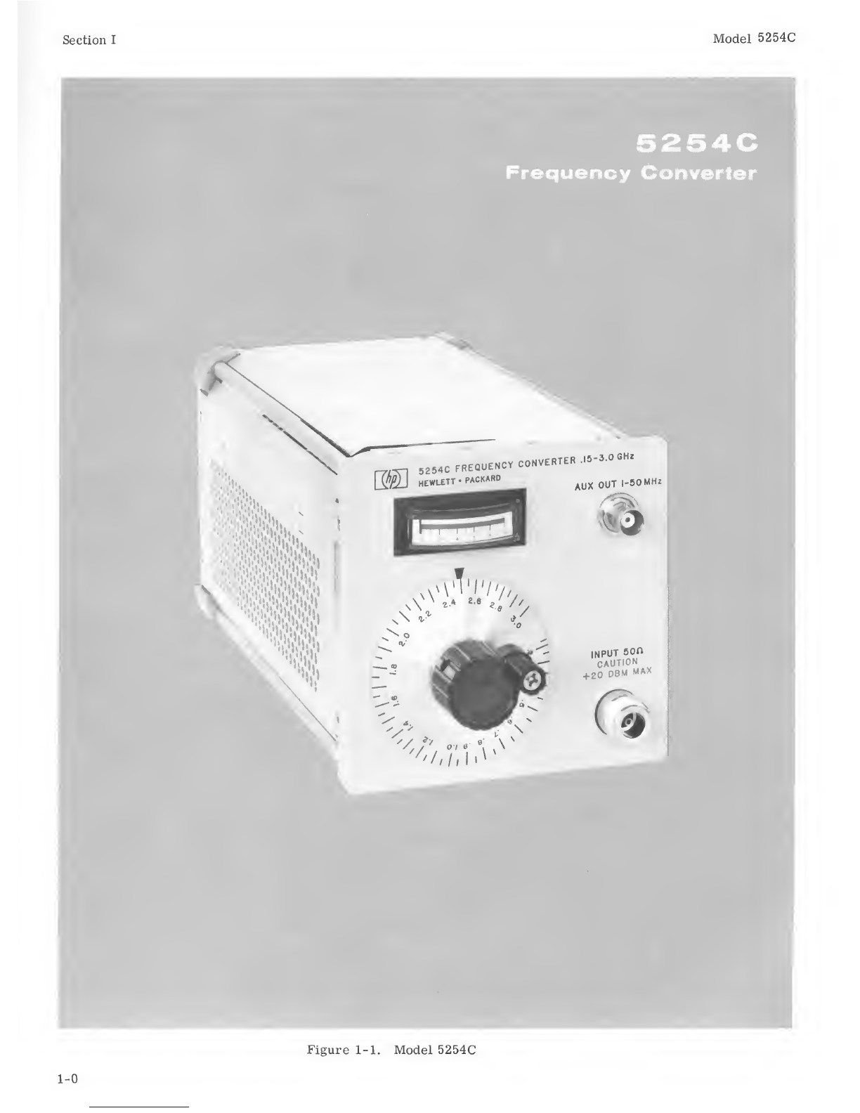
3-2. The Model 5254C Frequency Converter increases
the range of an HP Electronic Counter to. 15 through
3. 0GHz (150 through 3000 MHz). As ageneral rule
to measure frequency, always start with the Mixing
Frequency Control below .2GHz and tune upward in
frequency to obtain first response and tune for a
maximum reading in the green portion of the meter
scale. The input frequency is the sum of the counter
reading and the dial frequency reading. This proce-
dure will be valid whether there are responses in 1,
2, or 3consecutive harmonic reference frequencies;
see Figure 3-1. If the input signal level to the con-
verter is high, the second, third and other harmonics
of this signal may be generated. Therefore, tuning
Mixing Frequency Control from the low end upward
will enable the input fundamental frequency to be de-
tected before its harmonics. In the 5254C, harmonics
of the reference-frequency signals are held to such a
low level that regardless of input signal level, their
mixing effects are not observable, avoiding possible
ambiguity. Figure 3-1 provides astep-by-step pro-
cedure to be used for measurement of frequencies from
.15 to 3. 0GHz (150 MHz to 3000 MHz). The only ex-
ception is if the first response occurs at •15 GHz or
.25 GHz. To avoid possible ambiguity in these cases,
start from above .45 GHz and tune downward in fre-
quency for the first response and subtract the counter
reading from the dial frequency for the frequency of
the input signal.
Note
If the input frequency is known approximately,
the Mixing Frequency Control can be set a
hundred megahertz below the input signal. Tune
up for the first response and add the counter
reading to the dial frequency.
3-3. CONTROLS AND INPUT.
3-4. GENERAL. The function of the front panel con-
trol, meter, connectors, and retaining screws are
discussed in Paragraphs 3-5 through 3-8.
3-5. INPUT CONNECTOR. Signal input, 50 ohms in-
put impedance, 50 mV (-13 dBm in 50 ohms) to 1V
rms (+13 dBm in 50 ohms) into Type Nfemale
connector.
3-6. MIXING FREQUENCY SELECTOR. Calibrated
from .2to 3. 0GHz (200 MHz to 3000 MHz), this con-
trol tunes the internal cavity to select aharmonic of
50 MHz to be heterodyned with the INPUT signal.
3-7. LEVEL INDICATOR METER. The meter circuit
continuously monitors the level of the difference fre-
quency output of the converter to the counter. When
meter reads in the green portion of its scale, INPUT
signal amplitude is adequate for accurate frequency
measurement.
3-8. AUX OUT CONNECTOR. The 1MHz to 50 MHz
video amplifier output appears at AUX OUT BNC type
connector.
3-9. MAXIMUM INPUT VOLTAGES.
3-10. Damage to the converter may result if an ac
signal greater than +20 dBm in 50 ohms (2.2 Vrms)
or adc voltage greater than 100V is applied to the
converter INPUT connector.
3-11. FREQUENCY MEASUREMENT WITH
AMPLITUDE LESS THAN 50 MV RMS.
3-12. The front panel level indicator meter indicates
in the green portion of its scale only when converter
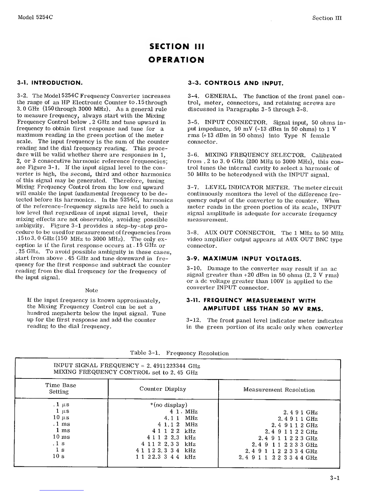
Table 3-1. Frequency Resolution
INPUT SIGNAL FREQUENCY =2.4911223344 GHz
MIXING FREQUENCY CONTROL set to 2. 45 GHz
Time Base
Setting Counter Display Measurement Resolution
.1 jl s*(no display)
1/IS 41.MHz 2. 491GHz
10 /is 4.11 MHz 2. 491 1 GHz
.1ms 41.1 2MHz 2. 49112 GHz
1ms 41122 kHz 2. 491122GHz
10 ms 41 1 22.3 kHz 2.4 911223GHz
.1s41122.3 3kHz 2. 491 1 2 2 33GHz
1s41122. 334kHz 2. 491 122334 GHz
10 s1 1 22.3 344kHz 2.491 1223344 GHz
3-1