Crestron MediaManager™ Applications Guide
the QM-RMCRX receiver, the accumulated skew over the entire 300 feet should
not exceed 15 ns.
QuickMedia supports UXGA (Ultra Extended Graphics Array) resolutions
(1600 x 1200 at 60 Hz vertical rate) at its maximum allowed cable length of 300
feet. The same path is used for the transport of composite and S-video which
ensures support that exceeds the requirements imposed by the highest broadcast
standards, as well as NTSC and PAL.
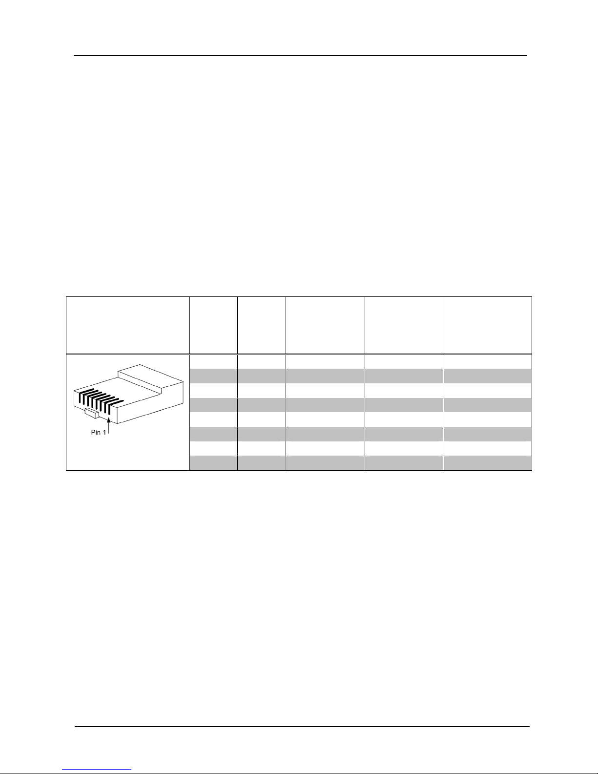
Pin Assignments for QuickMedia Transport
Systems
The pin assignment is based on the EIA/TIA 568B RJ-45 Jack standard.
To determine which pin is number 1, hold the cable so that the end of the eight
pin modular jack is facing you, with clip down and copper side up. When
looking down at the copper connections, pin 1 is on the far right.
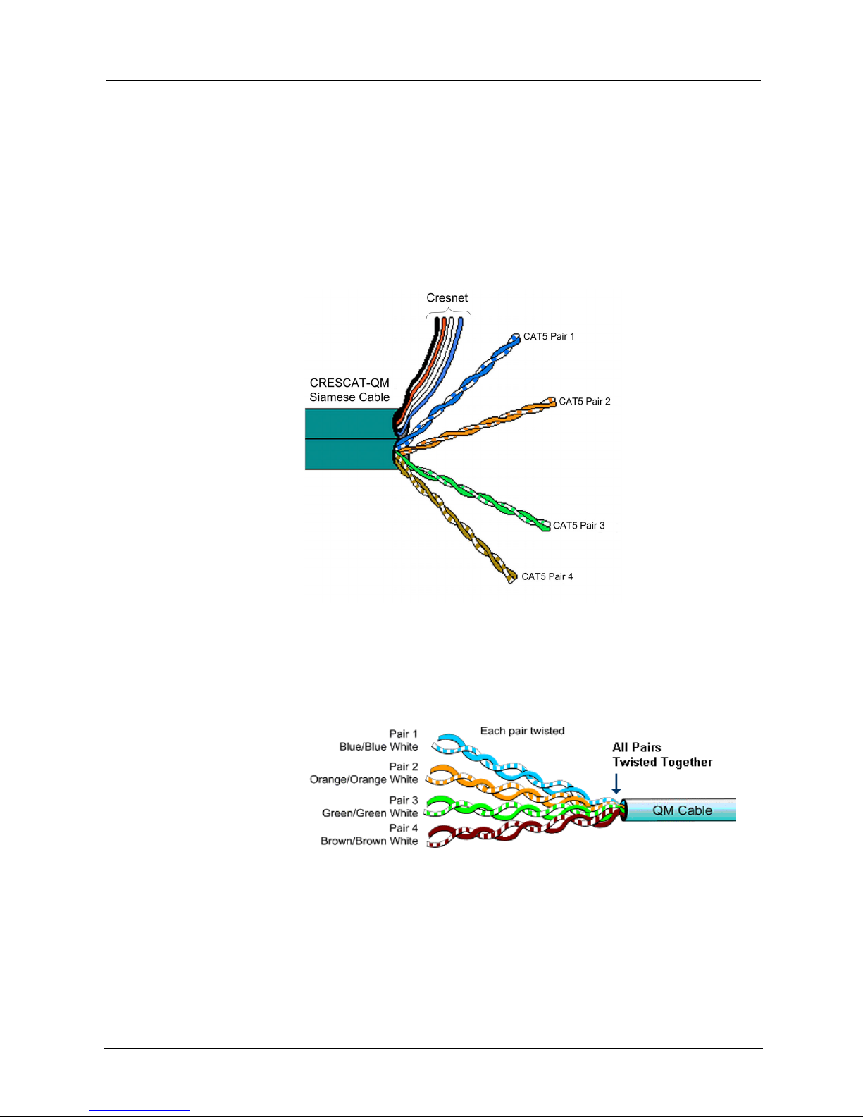
QuickMedia Pin and Pair Assignment
RJ-45 MALE
CONNECTOR
RJ-45
PIN #
CAT5E
PAIR #
WIRE COLORS QM
ASSIGNMENT
RGB AND
AUDIO
QM
ASSIGNMENT
COMPOSITE,
S-VIDEO AND
AUDIO
1 2 White/Orange - RGB Red - Chrominance
2 2 Orange + RGB Red + Chrominance
3 3 White/Green - RGB Green - Luminance
4 1 Blue + Audio + Audio
5 1 White/Blue - Audio - Audio
6 3 Green + RGB Green + Luminance
7 4 White/Brown - RGB Blue - Composite
8 4 Brown + RGB Blue + Composite
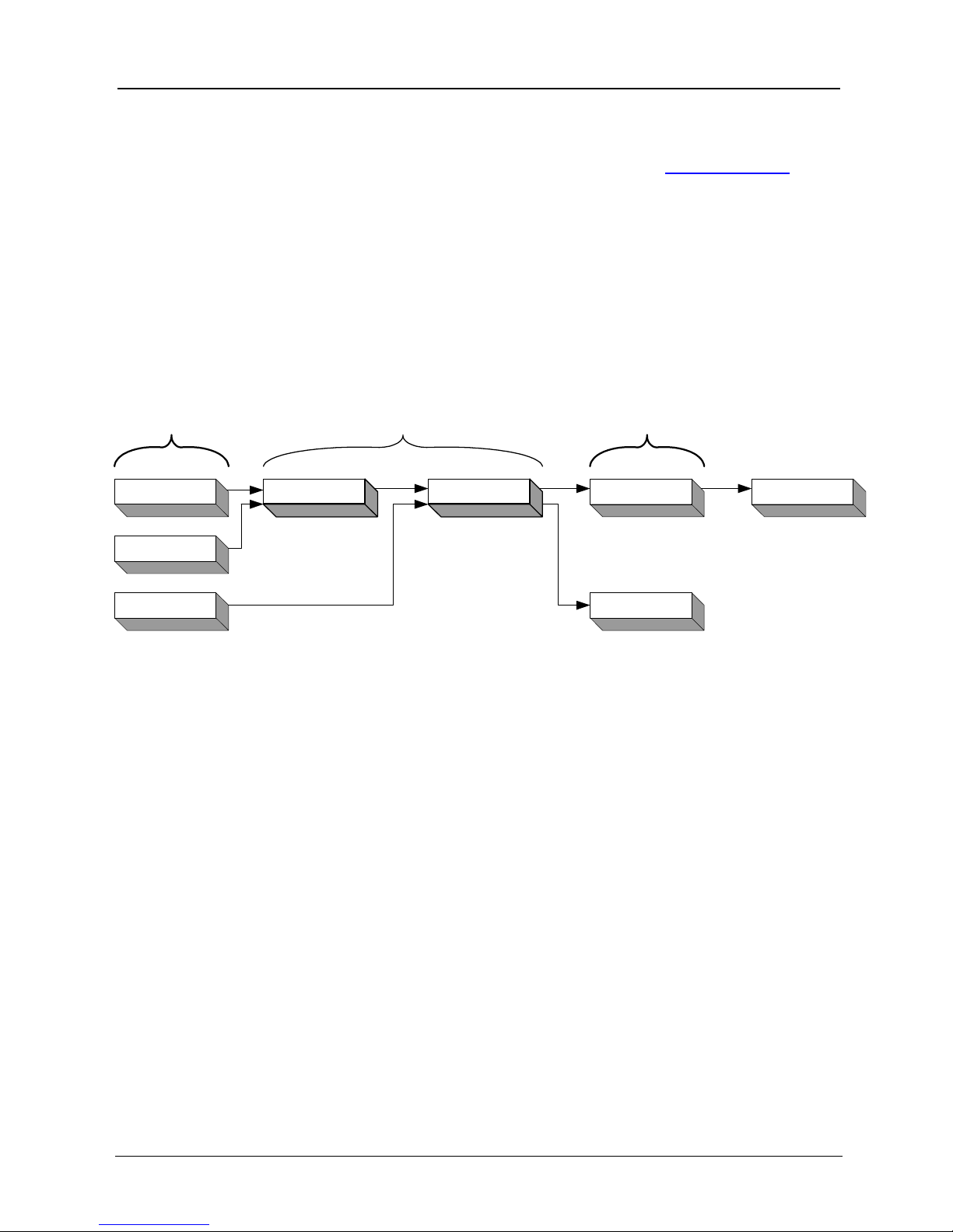
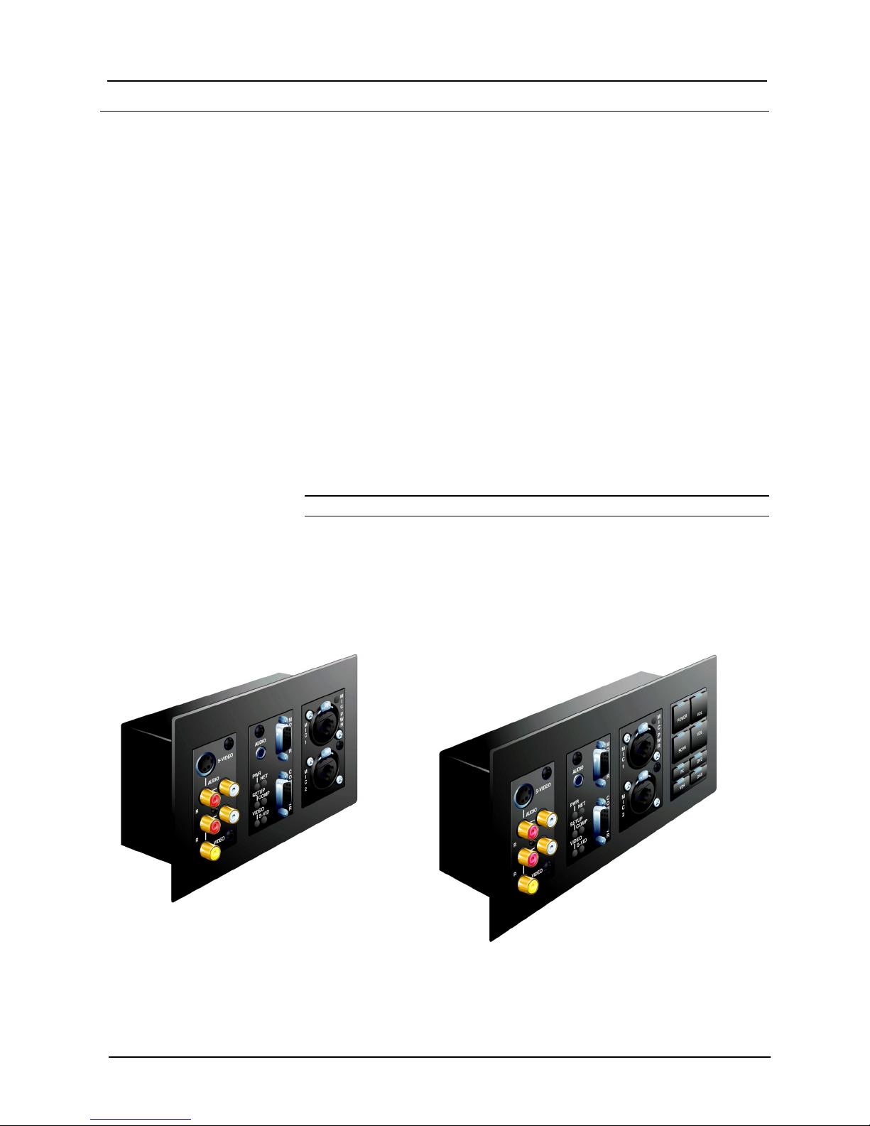
Display Device Selection for a QuickMedia
System
QuickMedia fully integrates the display device with the system. Consequently,
careful selection of a display device is required to take full advantage of this
capability. A projector should support discrete video switching commands. This
enables the QuickMedia receiver/processor to seamlessly pass along the three
different video types to the display and alert the display to switch inputs.
In addition, the display device should support discrete power on and off
commands. This enables a system “Room On” button function that will energize
the display. If the display device has a toggle on/off power command, there is a
possibility of getting out of sync with the room power. An option for displays
that toggle power on/off is to use the Crestron power sensor, however this
requires extra equipment and additional programming. Most RS-232 display
drivers in the Crestron database support discrete commands.
Applications Guide – DOC. 6244 Crestron MediaManager™ •3