Crestron CNIRT-32 User manual


CRESTRON CNRFT/CNIRT One-Way Wireless Panels
REMOTE CONTROL SYSTEMS
DOC. 8107
TABLE OF CONTENTS
DESCRIPTION................................................................................................................1
Functional Description......................................................................................1
CNRFT-32A/-48A..................................................................................1
CNIRT-32A/-48A...................................................................................1
Physical Description..........................................................................................2
Configuration Differences................................................................................2
LEADING SPECIFICATIONS.......................................................................................3
CONTROLS AND INDICATORS..................................................................................4
Controls..............................................................................................................4
Indicators.............................................................................................................4
INSTALLATION/SETUP...............................................................................................4
PROGRAMMING...........................................................................................................6
TEST/TROUBLESHOOTING........................................................................................7
FURTHER INQUIRIES....................................................................................................8
SYNTAX.........................................................................................................................9


CRESTRON CNRFT/CNIRT One-Way Wireless Panels
REMOTE CONTROL SYSTEMS
1 DOC. 8107
CRESTRON
1
13
25
37
14
26
38
23
15
27
39
4
16
28
40
5
17
29
41
6
18
30
42
7
19
31
43
8
20
32
44
9
21
33
45
10
22
34
46
12
24
36
48
11
23
35
47
6.2 in
15.7 cm
8.8 in
22.3 cm
11
19
27
CRESTRON
1
9
17
25
2
10
18
26
3
11
19
27
4
12
20
28
5
13
21
29
6
14
22
30
7
15
23
31
8
16
24
32
6.4 in
16.3 cm
6.2 in
15.7 cm
Figure 1. CNRFT/CNIRT, One-Way Wireless Panels
CNRFT-32A/CNIRT-32A
UNIT DEPTH 2.0 in (5.1 cm) UNIT DEPTH 2.0 in (5.1 cm)
CNRFT-48A/CNIRT-48A
DESCRIPTION:
The CNRFT-32A/CNIRT-32A and CNRFT-48A/CNIRT-48A are a new improved version of CRESTRON's
one-way wireless panels. The new "A" units are functionally identical to the non-"A" units, but the newer
unitshave beencompletely redesignedfor greaterease ofinstallation andmaintenance. Themanual rotary
switchesforID codesetting havebeen eliminatedandreplaced bya softwareutility program available
fromCRESTRON's Workshop.Theradio-frequency (RF)code packetshave beenupdated toinclude error
detection for higher reliability reception. The new improved one-way wireless panels must be used with
CRESTRON's new CNRFGWA or CNIRGWA receiver. The standard, high-quality non-"A" version
transmitters must continue to use the CNRFGW or CNIRGW.
Functional Description
CNRFT-32A/-48A
The CNRFT series of portable RF wireless panels, figure 1, is designed to operate with the CRESNET II
system with the use of a wireless receiver such as the CNRFGWA network unit. Up to 32 miniature
pushbuttons reside on the CNRFT-32A to provide direct user interface. The CNRFT-48A offers up to 48
miniaturepushbuttons.
CNIRT-32A/-48A
The CNIRT series of portable infrared (IR) wireless panels, figure 1, is designed to operate with the
CRESNET II system with the use of a wireless receiver such as the CNIRGWA network unit. Up to 32
miniature pushbuttons reside on the CNIRT-32A to provide direct user interface. The CNIRT-48A offers
upto48 miniaturepushbuttons.

CRESTRON CNRFT/CNIRT One-Way Wireless Panels
REMOTE CONTROL SYSTEMS
2 DOC. 8107
Physical Description
CNRFT-32A/48A and CNIRT-32A/48A electronic hardware is housed in a high-impact molded plastic
enclosure (refer to figures 1 and 2 for front and back views, respectively ). The button array on the printed
circuitboard iscoveredby acustomized buttonpanel. Allbutton panelsinclude customengraving, colored
buttoncaps, choiceofbutton configurations,and panelfinishes. Referto thelatest versionof the
CRESNET II Engraving Worksheet for the wireless transmitters (Doc. 5242 and Doc. 5243) to design a
uniquebutton panel.Omissionof unusedbuttons isstandard. Ared transmitLED islocated abovethe
buttonpanel cover.
BATTERY COVER W BATTERY
COVER.
OFINSIDEONMOUNTED
BATTERY COVER REMOVED TO
LOCATION.SENSORSHOW
Figure 2. CNRFT/CNIRT, Back View
A standard nine-volt battery is included with all units. Access to the battery is permitted after the
battery cover, located on the underside of the unit, is removed. A sensor (photo transistor) used to
programan identitycodeis alsolocated inthe batterycompartment.
Configuration Differences
TheRF and IRone-way wirelesstransmitters havetwo differentconfigurations basedonthe maximum
numberof buttonsavailable onthe customizedpanel. Theyaredepicted intable 1.
Table 1. CNRFT-32A/48A and CNIRT-32A/48A Configurations
CONFIGURATION DESCRIPTION
CNRFT-32A & CNIRT-32A 32buttonsona customizedpanel
CNRFT-48A & CNIRT-48A 48buttonsona customizedpanel

CRESTRON CNRFT/CNIRT One-Way Wireless Panels
REMOTE CONTROL SYSTEMS
3 DOC. 8107
LEADING SPECIFICATIONS:
Table 2 provides a summary of leading specifications for the wireless transmitters. Dimensions and
weightareapproximations roundedto thenearest tenthunit.
Table 2. Leading Specifications
SPECIFICATION DETAILS
Battery 9V DC
CRESNET II Workshop Version 5.0 or later
CRESNET II Operating System SR30160.OPS or later
CNRFT-32A & CNIRT-32A
Dimensions& Weight Height: 6.2 in (15.7 cm)
Width: 6.4 in (16.3 cm)
Depth: 2.0 in (5.1 cm)
Weight: 0.7 lb (0.3 kg)
CNRFT-48A & CNIRT-48A
Dimensions& Weight Height: 6.2 in (15.7 cm)
Width: 8.8 in (22.3 cm)
Depth: 2.0 in (5.1 cm)
Weight: 1.0 lb (0.5 kg)
NOTE This equipment has been tested and found to comply with the limits for a Class B
digital device, pursuant to part 15 of the FCC Rules. These limits are designed to
provide reasonable protection against harmful interference in a residential
installation. This equipment generates, uses and can radiate radio frequency energy
and, if not installed and used in accordance with the instructions, may cause harmful
interference to radio communications. However, there is no guarantee that
interference will not occur in a particular installation. If this equipment does cause
harmful interference to radio or television reception, which can be determined by
turning the equipment off and on, the user is encouraged to try to correct the
interference by one or more of the following measures:
- Reorient or relocate the receiving antenna.
- Increase the separation between the equipment and receiver.
- Connect the equipment into an outlet on a circuit different from that to which the
receiver is connected.
- Consult the dealer or an experienced radio/TV technician for help.

CRESTRON CNRFT/CNIRT One-Way Wireless Panels
REMOTE CONTROL SYSTEMS
4 DOC. 8107
CONTROLS AND INDICATORS:
Controls
Button controls are custom designed. The wireless transmitters are available with a maximum of 32 to
48functional buttons(dependingon themodel). Functiondefinition isdetermined byapplication ofthe unit
withintheCRESNET IIsystem. Thecustomized buttoncontrolscorrespond tosignal namesthat are
definedin theSIMPL program.
Indicators
There is only one indicator located on the wireless transmitters. The indicator is a red LED and resides on
theface oftheunit abovethe buttonpanel cover.The transmitLED indicatesIR/RF transmissionand
illuminateswhen abuttonis depressed.
INSTALLATION/SETUP:
Every wireless transmitter communicating with either the CNRFGWA or CNIRGWA requires a unique
identity code (ID CODE). For RF devices the ID CODE is referred to as RF ID. For IR devices the ID CODE is
referred to as IR ID. There are 254 possible two-digit hexadecimal alphanumeric codes ranging from 01 to
FE. The CNRFT/CNIRT ID CODE is factory set to 11, but may be changed from a PC via CRESTRON's
CRESNETII Workshop.An IDCODE mayneed tobe changedif morethan onetransmitter isplaced onthe
network. To maintain code diversity within the CRESNET II system, use codes between 10 and FE for the
transmitters.
NOTES
1. The ID CODE on the wireless transmitters is factory set to 11.
2. If an ID CODE needs to be changed, do not use 00 or FF as an RF/IR ID.
3. Do not confuse RF/IR ID with network (NET) ID.
The following items are required to change the wireless transmitter ID CODE:
• PC running CRESNET II Workshop, version 5.0 or later.
• CNIDC- Identity Codecable.
Completethe followingstepsin theorder providedto ensureproper IDCODE assignmentof theunit.
1. Start upthe CRESNETII Workshopwith the followingDOS commands.
CD\CN2 (depress ENTER)
CNWS (depress ENTER)
2. The Workshopcommences withan openingscreen. Depressany keyto openthe MAINMENU,
illustrated in figure 3.

CRESTRON CNRFT/CNIRT One-Way Wireless Panels
REMOTE CONTROL SYSTEMS
5 DOC. 8107
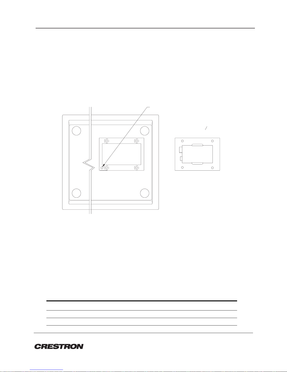
3. From the MAIN MENU, highlight Utilities and depress ENTER. The UTILITY MENU, illustrated in
figure4, appearson thedisplay.
Figure 3. MAIN MENU, Workshop
CRESNET II Workshop v5.0
ESC to Quit Alt[D] = Set Defaults F1=Help
MAIN MENU
SIMPL
RIPE
Sort IR drv
Utilities
Quit
Enter the SIMPL (Symbol - Intensive - Master - Programming -
Language) program development environment.
Figure 4. UTILITY MENU, Workshop
CRESNET II Workshop v5.0
ESC to Main Menu Alt[D] = Set Defaults F1=Help
Transmitter ID Programmer
UTILITY MENU
performance Viewport
load/save Touch panels
Print touch panel
OS Upgrade
CPU
DEAL
Easykey programmer
load/save Nvram
TID
Leave Utilities
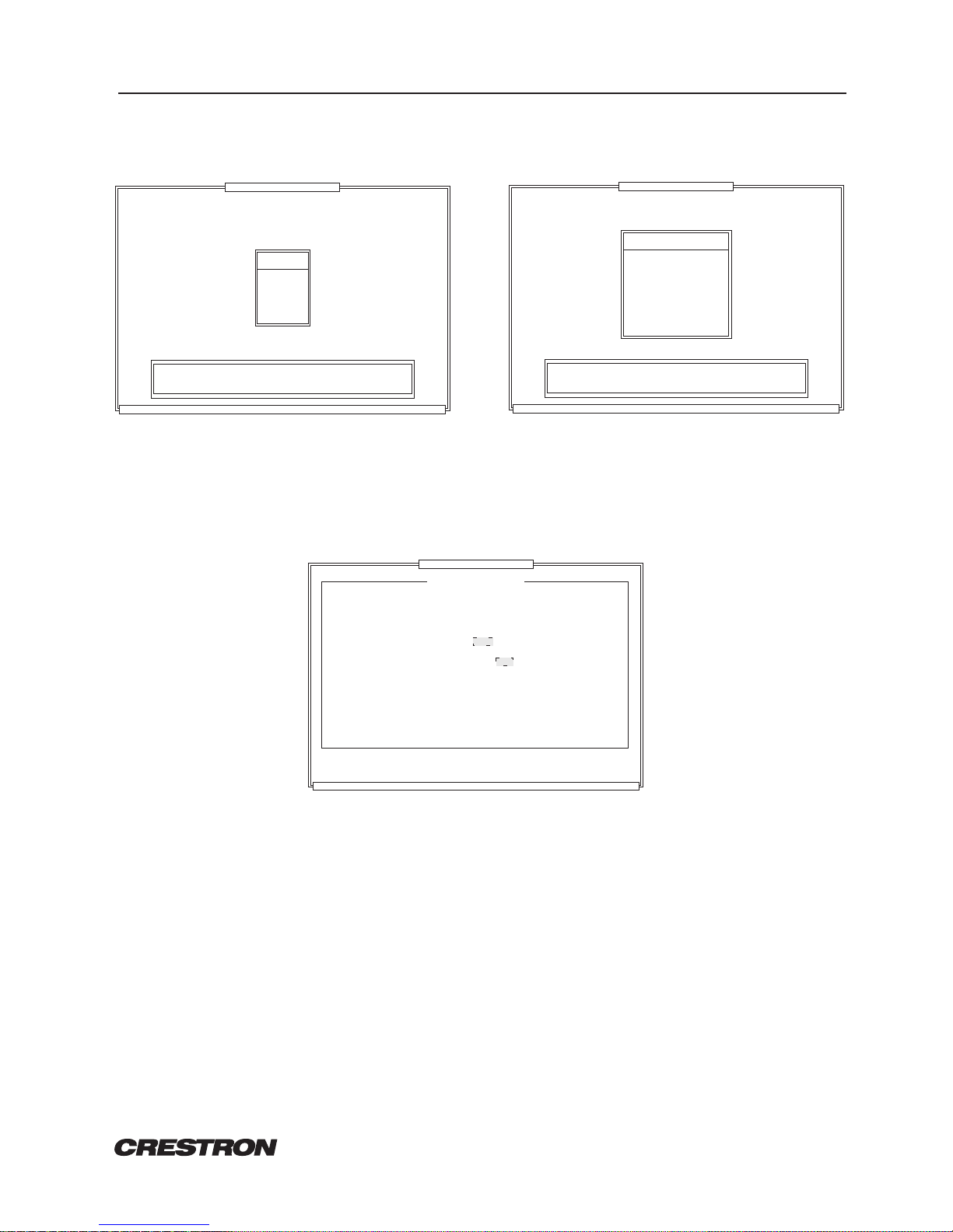
4. From theUTILITY MENU,highlight TIDand depress ENTER.The TransmitterID Programmer,
illustrated in figure 5, appears on the display.
CRESNET II Workshop v5.0
ESC-Utility Menu
TAB-Select COM
F1-Help Enter-Program the transmitter
Transmitter ID Programmer
Figure 5. Transmitter ID Programmer, Workshop
Position IR probe over sensor on transmitter.
RS-232 COM port:
Type RF id code in HEX:
COM1
Hit Enter to program the transmitter ID
Do not remove IR probe until it stops blinking
5. From the Transmitter ID Programmer screen, specify the PC's COM port with the TAB key.
6. Connect the9-pin DINconnector fromthe CNIDCtothe properCOM porton theback ofthe PC. Use
thesame portasthat assignedin theprevious step.
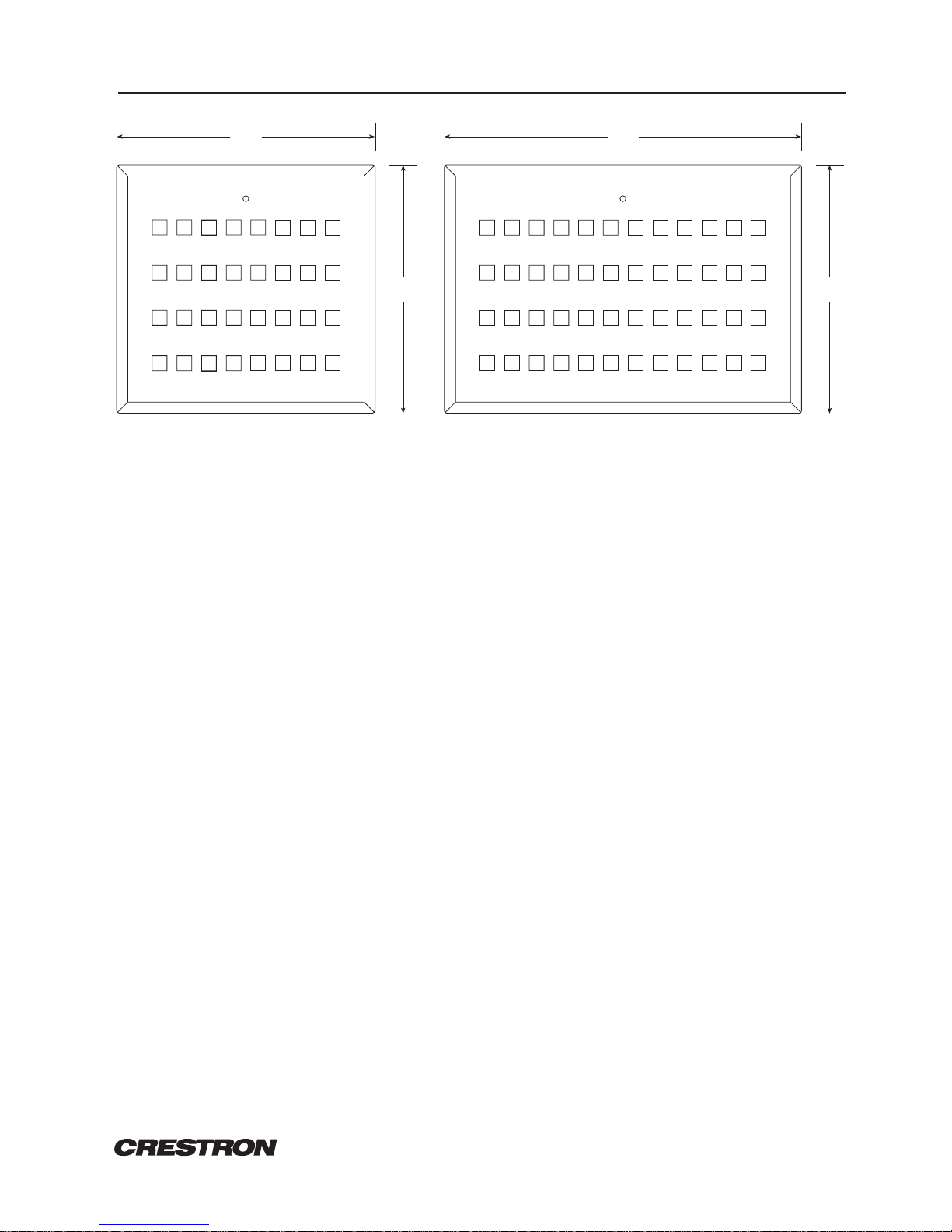
7. Position the transmitter button-side down so the battery compartment is accessible.
8. Remove thebattery coverto exposethe batterycompartment. Referto figure2.
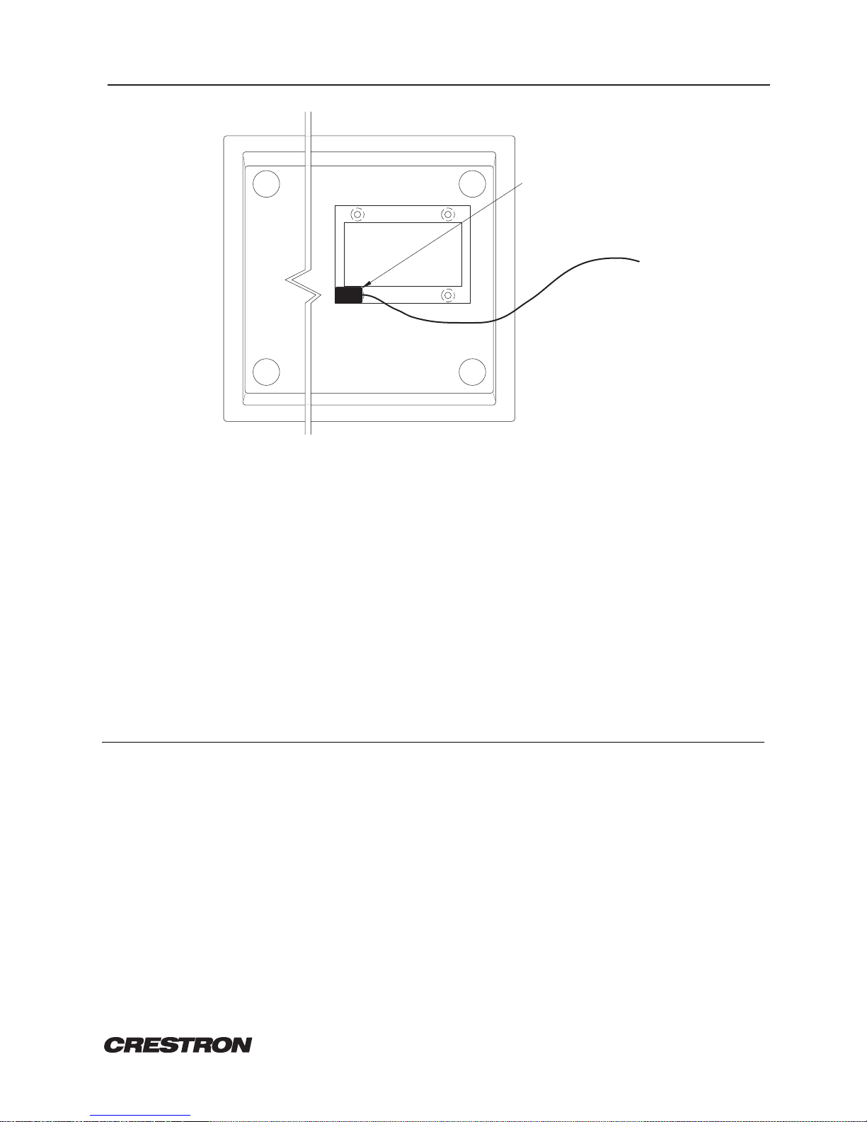
9. Place LEDprobe fromthe CNIDCover theexposed sensor (phototransistor) asshown infigure 6.The
probeshouldrest inthe cornerof thebatterycompartment sothat itcompletely covers thesensor.

CRESTRON CNRFT/CNIRT One-Way Wireless Panels
REMOTE CONTROL SYSTEMS
6 DOC. 8107
PROBE SHOULD COVER
SENSOR SHOWN.AS
Figure 6. Probe Placement
10. With a finger over the probe to hold it in place, lift and rotate transmitter so that the red LED located
abovethe button panelis visible.
11. From thePC, typethetwo-digit hexadecimalID CODE.
12. Depress theENTER keyandobserve theflashing redLED onthe frontof the transmitter.
13. Whenthe redLED stopsflashing, removethe probefromthe backof theunit. TheID CODEis
programmedinto thetransmitter.
14. Secure thebattery cover overthe batterycompartment.
15. Disconnect theCNIDC fromthe PC.
PROGRAMMING:
Thebuttonarray islocated beneaththe custombuttonpanel ofeach wirelesstransmitter. Refer tofigure
1forthe locationof theSIMPL-C buttonnumbersand theircorresponding buttonpositions for theCNIRT
andCNRFT transmitters.Thenumbering foreach buttonis constant.For eachbutton input,a signalname
mustbe definedin theSIMPL program.Unused buttonsneednot beassigned signalnames. Thefollowing
example illustrates button definition of the CNRFT-32A and CNIRT-32A in the CRESNET II Workshop.
Access the following tables from the "Define Network" section of the SIMPL-I Menu. Aside from
difference in nomenclature, the Workshop menus of the CNRFT-48A and CNIRT-48A are identical.

CRESTRON CNRFT/CNIRT One-Way Wireless Panels
REMOTE CONTROL SYSTEMS
7 DOC. 8107
ESC to Def Equip F1=HelpDefine Network
TAB to select entries
F3-Display Signals
PgUp/PgDn to find ID
F2-Detail
Net PF: 3.0System PF :
P.F.DescriptionNet DeviceNet ID
3.0
03:
CRESNET II Workshop v5.0
04:
05:
06:
07:
08:
09:
0A:
0E:
0F:
10:
11:
12:
0B:
0C:
0D:
CNRFGW CNRFGW/CNIRGW Receiver 3.0
ESC to Define Net F1=HelpPanel Detail
F4- Auto-Increment
CNIRT-32
CRESNET II Workshop v5.0
1:
F2-Detail
BUTTON SIGNAL NAMES
2:
3:
4:
5:
6:
7:
8:
9:
F3-Display Signals
10:
11:
12:
13:
14:
CNRFGW
RF ID: 14
Net ID: 03
ESC to Define Net F1=HelpPanel Detail
to Enter ID
CNRFGW
CRESNET II Workshop v5.0
CNRFGW/CNIRGW Receiver
TAB - Select Transmitter
Net ID: 03
F2-Detail
32-button 1-way transmitter
Transmitter
RF ID Description
12
14 CNRFT-32
CNIRT-32 32-button 1-way IR transmitter
ESC to Define Net F1=HelpPanel Detail
F4- Auto-Increment
CNRFT-32
CRESNET II Workshop v5.0
1:
F2-Detail
BUTTON SIGNAL NAMES
2:
3:
4:
5:
6:
7:
8:
9:
F3-Display Signals
10:
11:
12:
13:
14:
CNRFGW
RF ID: 12
Net ID: 03
TEST/TROUBLESHOOTING:
Table 3 provides corrective action for possible trouble situations. If further assistance is required, please
contact a CRESTRON technical support representative.
Table 3. Troubleshooting Guide
TROUBLE POSSIBLE CAUSE(S) CORRECTIVE ACTION
LEDon unitdoes not
illuminate. No battery in unit or battery is dead. Install new battery.
Intermittent
responseduring Refer tocause whenLED doesnotilluminate. Refer tocorrective actionwhen LEDdoes not
illuminate.
transmission. Receiveris blockedor moved. For IR unit, verify direct line-of-sight. For RF
unit, verify that heavy metal is not in vicinity
oftransmission.
CNRFGWA is in vicinity of metal. Verify that largeamount of metalis not
blockingtransmission.

CRESTRON CNRFT/CNIRT One-Way Wireless Panels
REMOTE CONTROL SYSTEMS
8 DOC. 8107
Table 3. Troubleshooting Guide (Continued)
TROUBLE POSSIBLE CAUSE(S) CORRECTIVE ACTION
Noresponse from
CRESNETII system. Referto causeswhen LEDdoes notilluminate and
intermittent response during transmission occurs. Referto corrective actionwhen LEDdoes not
illuminateand intermittent responseduring
transmission occurs.
NET ID of receiver is incorrectly set. Enter Performance Viewport in the CRESNET II
Workshop. Depress the F4 key to poll the
network. Verify that the NET ID for the
receiver is properly set to match the SIMPL
program.
NOTE:
After changing the CNRFGWA/CNIRGWA
identitycode, disconnectand reconnectthe
networkconnector.
RF ID or IR ID is incorrectly set. Verify that the RF ID or IR ID for the
transmitter is properly set to match the
SIMPLprogram.
NOTE:
NETIDand RFID orIR IDareseparate
parameters. ALT-R in Workshop (v5.0)
shows RF or IR transmitter button presses.
Program does not matchhardware. Verify correct program is loaded in system via
PerformanceViewport Workshop.
Receiver is unplugged (nopower). Verify power to the receiver.
Two or more receiversare too close together. Verify that multiple receivers are properly
spaced(>50 feet)from eachother.
Wrong transmitter in use. If multiple transmitters are accessible, verify
properunit isused.
FURTHER INQUIRIES:
If after reviewing this Operations Guide you still have additional questions, please contact a CRESTRON
technical support representative by dialing (888) CRESTRON [(888) 273-7876] or (201) 894-0660.

CRESTRON CNRFT/CNIRT One-Way Wireless Panels
REMOTE CONTROL SYSTEMS
9 DOC. 8107
SYNTAX:
Thefollowingsyntax codesare providedfor compatibilitypurposesonly.
NET.ID <10 o FE>: CNRFGW \CNRFT talking to a CNRFGWA
TRANSMITTER <RF IDCODE >: CNRFT \ID # and transmitter type.
i1 = <signal name> \Independent button.
i2 = <signal name>
i3 = <signal name>
" = " "
NET.ID <10 o FE>: CNIRGW \CNIRT talking to a CNIRGWA
TRANSMITTER <IR IDCODE >: CNIRT \ID # and transmitter type.
i1 = <signal name> \Independent button.
i2 = <signal name>
i3 = <signal name>
" = " "

Other manuals for CNIRT-32
1
This manual suits for next models
2
Table of contents
Other Crestron Other manuals

Crestron
Crestron TPS-FPAR2000L User manual

Crestron
Crestron Media Manager User guide

Crestron
Crestron CNIRT-32 User manual

Crestron
Crestron CNWP-32 User manual

Crestron
Crestron VT-3500IMW Instruction Manual

Crestron
Crestron CNPCI-8 User manual

Crestron
Crestron CAGE2 User manual

Crestron
Crestron iLux CLSI-C6 User manual

Crestron
Crestron CAT5 User manual

Crestron
Crestron CAT5 User manual