Crestron DM-RMC-100-STR Owner's manual

DM-RMC-100-STR
HD Streaming Receiver and
Room Controller 100
Supplemental Guide
Crestron Electronics, Inc.

The product warranty can be found at www.crestron.com/warranty.
The specific patents that cover Crestron products are listed at patents.crestron.com.
Certain Crestron products contain open source software. For specific information, please visit www.crestron.com/opensource.
Crestron, the Crestron logo, Crestron Toolbox, and DigitalMedia are either trademarks or registered trademarks of Crestron Electronics, Inc.
in the United States and/or other countries. HDMI, the HDMI logo, and High Definition Multimedia Interface are either trademarks or registered
trademarks of HDMI Licensing LLC in the United States and/or other countries. Other trademarks, registered trademarks, and trade names
may be used in this document to refer to either the entities claiming the marks and names or their products. Crestron disclaims any
proprietary interest in the marks and names of others. Crestron is not responsible for errors in typography or photography.
This document was written by the Technical Publications department at Crestron.
©2015 Crestron Electronics, Inc.

Supplemental Guide – DOC. 7846A Contents
•
i
Contents
Introduction 1
User Interface Overview 1
Accessing the User Interface................................................................................... 1
Opening a Web Browser Directly ............................................................... 2
Opening a Web Browser within the Crestron Toolbox Application.............. 2
Logging In to the DM-RMC-100-STR......................................................... 3
Navigating the User Interface .................................................................................. 4
Status and Configuration 5
Viewing DM-RMC-100-STR Status Information....................................................... 5
Configuring Stream Settings ................................................................................... 6
Configuring On-Screen Display Settings................................................................ 11
Configuring Text Overlay Settings ............................................................ 11
Configuring Image Overlay Settings.......................................................... 12
Configuring HDMI Output Settings ........................................................................ 14
Configuring Network Settings................................................................................ 16
Configuring Device Settings .................................................................................. 17
Configuring Control System Connection Settings..................................... 17
Changing the User Name and Password ................................................. 18
Controlling the Display of the LEDs .......................................................... 18
Upgrading Firmware................................................................................. 19
Restoring Factory Default Settings ........................................................... 20
Rebooting the DM-RMC-100-STR ........................................................... 20


Supplemental Guide – DOC. 7846A DM-RMC-100-STR: HD Streaming Receiver
•
1
DM-RMC-100-STR: HD Streaming
Receiver and Room Controller 100
Introduction
The Crestron®DM-RMC-100-STR is an H.264 streaming decoder designed to receive
high-definition AV signals over an IP network. The DM-RMC-100-STR decodes the H.264
streaming signal from a DigitalMedia™ switcher, IP camera, or other streaming source, and
then outputs an HDMI®signal to feed the input of a display device, AV receiver, or switcher.
The web-based user interface of the DM-RMC-100-STR facilitates configuration of the
DM-RMC-100-STR from a laptop. Extensive configuration, control, and monitoring of the
DM-RMC-100-STR are also provided through integration with a Crestron control system.
This guide provides information about configuration of the DM-RMC-100-STR using the
web-based user interface. For additional information, refer to the DM-RMC-100-STR DO
Guide (Doc. 7651).
User Interface Overview
The user interface of the DM-RMC-100-STR consists of built-in web pages that allow
configuration of stream, on-screen display, HDMI output, network, and device settings.
In addition, information about the DM-RMC-100-STR as well as the connected display can
be viewed.
Accessing the User Interface
The user interface is accessed from a web browser. To access the user interface, do either
of the following:
•Open a web browser directly. Refer to “Opening a Web Browser Directly” on the
following page for additional information.
•Open a web browser within the Crestron Toolbox™ application. Refer to “Opening
a Web Browser within the Crestron Toolbox Application” on the following page for
additional information.

2
•
DM-RMC-100-STR: HD Streaming Receiver Supplemental Guide – DOC. 7846A
Opening a Web Browser Directly
To access the user interface by opening a web browser directly, do the following:
1. Find the IP address or host name of the DM-RMC-100-STR by doing either of the
following, respectively:
•To find the IP address, press the
SETUP
button on the device and note the
IP address on the connected display. The IP address appears for
10 seconds.
•To find the default host name, locate the label on the rear of the device or
on a mounting flange of the device and note the host name.
NOTE:
The default host name is DM-RMC-100-STR-xxxxxxxxxxxx, where
xxxxxxxxxxxx is the MAC address of the device.
NOTE:
The host name can be changed. For additional information, refer to
“Configuring Network Settings” on page 16.
2. Open a web browser.
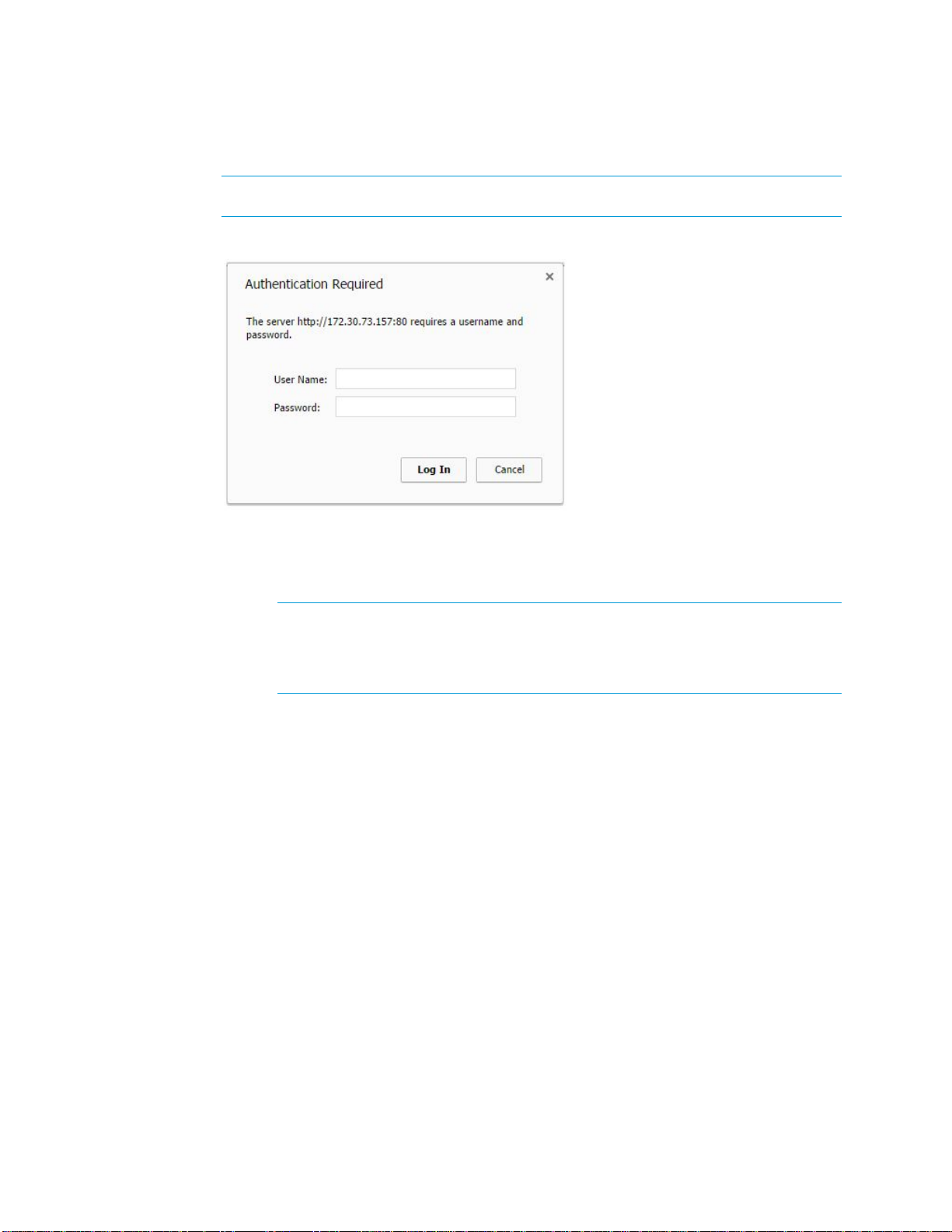
3. Go to the IP address or host name of the DM-RMC-100-STR.
The user name and password dialog box opens, allowing login to the
DM-RMC-100-STR. For login information, refer to “Logging In to the
DM-RMC-100-STR” on the following page.
Opening a Web Browser within the Crestron Toolbox Application
To access the user interface by opening a web browser within the Crestron Toolbox
application, do the following:
1. Open the Crestron Toolbox application.
2. From the
Tools
menu, select
Device Discovery Tool.
NOTE:
You can also access the Device Discovery Tool by clicking the Device
Discovery Tool button ( ) in the toolbar.
NOTE:
The security software running on the computer may send a program alert
regarding the attempt of the Crestron Toolbox application to connect to the
network. Allow the connection so that the Device Discovery Tool can be used.
3. From the device list on the left-hand side of the screen, double-click
DM-RMC-100-STR
.
A browser window opens, and then the user name and password dialog box
opens, allowing login to the DM-RMC-100-STR. For login information, refer to
“Logging In to the DM-RMC-100-STR” on the following page.

Supplemental Guide – DOC. 7846A DM-RMC-100-STR: HD Streaming Receiver
•
3
Logging In to the DM-RMC-100-STR
The user name and password dialog box allows login to the DM-RMC-100-STR.
NOTE:
Depending on the web browser being used, the user name and password dialog
box may vary from the dialog box shown below.
User Name and Password Dialog Box
To log in to the DM-RMC-100-STR, do the following:
1. Enter the user name and password. The default user name is admin, and the
default password is admin.
NOTE:
The user name and password are case sensitive.
NOTE: For enhanced security, it is recommended that the default user name and
password bechanged. Forinformation about changing the user name and
password, refer to “Changing the User Name and Password" on page 18.
2. Click the button that allows login to the DM-RMC-100-STR. If the browser being
used displays the same dialog box as the one shown above, click
Log In
.
The Status page, which is the home page of the user interface, opens.
For information about navigating the user interface, refer to “Navigating the User
Interface” on the following page.

4
•
DM-RMC-100-STR: HD Streaming Receiver Supplemental Guide – DOC. 7846A
Navigating the User Interface
The user interface provides a navigation bar and built-in web pages of the
DM-RMC-100-STR.
DM-RMC-100-STR User Interface (Status Page Shown)
The navigation bar provides access to the web pages as follows:
•Clicking
Status
accesses the Status page, which provides general information
about the DM-RMC-100-STR as well as network-related information. For additional
information, refer to “Viewing DM-RMC-100-STR Status Information” on the
following page.
•Clicking
Stream
accesses the Stream page, which allows configuration of the
DM-RMC-100-STR as a streaming decoder. For additional information, refer to
“Configuring Stream Settings” on page 6.
•Clicking
On-Screen Display
accesses the On-Screen Display page, which allows
text or an image—or both—to be overlaid on the connected display. For additional
information, refer to “Configuring On-Screen Display Settings” on page 11.
•Clicking
HDMI Output
accesses the HDMI Output page, which allows various
settings, such as the output resolution, to be set. In addition, the output can be
enabled or disabled. For additional information, refer to “Configuring HDMI Output
Settings” on page 14.
•Clicking
Network
accesses the Network page, which allows network settings such
as host name, domain name, and DHCP (Dynamic Host Configuration Protocol)
mode to be set. For additional information, refer to “Configuring Network Settings”
on page 16.
•Clicking
Device
accesses the Device page, which sets up connection to a control
system, allows changes to user name and password settings, and controls various
device functions. For additional information, refer to “Configuring Device Settings”
on page 17.

Supplemental Guide – DOC. 7846A DM-RMC-100-STR: HD Streaming Receiver
•
5
Status and Configuration
The web-based user interface of the DM-RMC-100-STR displays status information and
allows configuration of the following:
•Stream settings
•On-screen display settings
•HDMI output settings
•Network settings
•Device settings
Viewing DM-RMC-100-STR Status Information
General information, such as model name, serial number, and firmware version of the
DM-RMC-100-STR, can be viewed. The current network settings, such as host name and
IP address, can also be viewed.
To view status information, do the following: In the navigation bar, click
Status
. The Status
page opens.
NOTE:
The Status page opens after logging in to the DM-RMC-100-STR.
Sample Status Page
The Status page displays the following information about the DM-RMC-100-STR:
•General information, which consists of the following:
oModel, which is
DM-RMC-100-STR
oSerial Number
oFirmware Version

6
•
DM-RMC-100-STR: HD Streaming Receiver Supplemental Guide – DOC. 7846A
oApplication Version
oIP ID
oController
•Network-related information, which consists of the following:
oHost Name
NOTE:
In the sample Status page shown on the previous page, the
default host name is DM-RMC-100-STR-00107f36fc84, where
00:10:7f:36:fc:84 is the MAC address of the device.
oIP Address
oSubnet Mask
oDefault Gateway
oMAC Address
Configuring Stream Settings
To configure stream settings, do the following:
1. In the navigation bar, click
Stream
. The Stream page opens.
Stream Page
2. Configure stream settings. Refer to the following table for stream configuration
guidelines. In addition, refer to the Streaming Design Guide (Doc. 7610) at
www.crestron.com/manuals for information about DigitalMedia streaming.

Supplemental Guide – DOC. 7846A DM-RMC-100-STR: HD Streaming Receiver
•
7
Stream Configuration Guidelines
CONFIGURATION
ITEM
GUIDELINES
Initiation Specifies the streaming method used to determine when the
DM-RMC-100-STR is to begin streaming. In the
Initiation
drop-down
list, select one of the following:
•
By Receiver:
(Default setting) Specifies a unicast RTSP,
HLS (HTTP Live Streaming), or MPEG DASH (Dynamic Adaptive
Streaming over HTTP) stream. The DM-RMC-100-STR
attempts to connect to the transmitting device whose address
is specified in the
Stream Location
text box. The stream must
be configured before the DM-RMC-100-STR can connect to
the transmitting device. Refer to the documentation of the
transmitting device for information about configuring the device.
•
By Transmitter:
Specifies a unicast UDP stream.
The DM-RMC-100-STR waits for an incoming connection from
a client. When the client connects, the initiation session
parameters are exchanged and the stream begins.
•
Multicast via RTSP:
Specifies a multicast RTSP stream.
The DM-RMC-100-STR attempts to connect to the transmitting
device whose address is specified in the
Stream Location
text
box. The stream must be configured before the
DM-RMC-100-STR can connect to the transmitting device.
Refer to the documentation of the transmitting device for
information about configuring the device.
When the stream starts, the multicast address is displayed in
the
Detected Multicast Address
field (read only).
•
Multicast via UDP:
Specifies a multicast UDP stream.
The DM-RMC-100-STR begins streaming to the multicast IP
address specified in the
Stream Location
text box.
Stream Location (Enabled only when
Initiation
is set to
By Receiver
,
Multicast via
RTSP
, or
Multicast via UDP
) Enter the stream location using the
standard scheme format:
•For
By Receiver:
oWhen
By Receiver
specifies a unicast RTSP stream,
enter the RTSP URL, for example:
rtsp://streaming.server.com:544/path/to/file.sdp
oWhen
By Receiver
specifies an HLS stream, enter the
HTTP URL, for example:
http://hls.server.com:8080/stream.m3u8
oWhen
By Receiver
specifies an MPEG DASH stream,
enter the HTTP URL, for example:
http://localhost:1935/live/myStream/manifest.mpd
•For
Multicast via RTSP,
enter the RTSP URL, for example:
rtsp://streaming.server.com:544/path/to/file.sdp
•For
Multicast via UDP,
enter the multicast IP address in dotted
decimal notation, for example:
225.1.1.1
(Continued on following page)

8
•
DM-RMC-100-STR: HD Streaming Receiver Supplemental Guide – DOC. 7846A
Stream Configuration Guidelines (Continued)
CONFIGURATION
ITEM
GUIDELINES
Stream Type Specifies the stream type. Click one of the following radio buttons:
•
MPEG-2 TS Encapsulated:
Allows the DM-RMC-100-STR to
receive incoming MPEG-2 TS streams. Only one port number is
consumed by the encapsulation. The default port number is
4570
. Refer to the documentation of the transmitting device to
verify that it can encapsulate the stream in MPEG-2 TS.
•
Independent RTP Streams:
(Default setting) Allows the
DM-RMC-100-STR to stream the audio and video as separate
RTP streams. Each RTP stream uses a different port. Refer to
the documentation of the transmitting device to verify that this
setting should be used.
The
Detected Stream Type
field (read only) displays the stream type
as
MPEG-2 TS Encapsulated, Independent RTP Streams,
or
Unknown
.
Custom Ports Enables or disables the assignment of custom port numbers for the
selected Initiation method (
By Receiver
,
By Transmitter, Multicast via
RTSP,
or
Multicast via UDP
). By default, the
Enable
check box is
deselected. The default port numbers are as follows:
•For
By Receiver
, the default port number is
554
.
•For
By Transmitter
, the default port numbers are as follows:
oIf
Stream Type
is set to
MPEG-2 TS Encapsulated
, the
default port number is
4570
.
oIf
Stream Type
is set to
Independent RTP Streams
, the
default video port number is
49170
and the default
audio port number is
49172
. The audio port number is
always the next even-numbered port number following
the video port number.
•For
Multicast via RTSP
, the default port number is
554
.
•For
Multicast via UDP
, the default port numbers are as follows:
oIf
Stream Type
is set to
MPEG-2 TS Encapsulated
, the
default port number is
4570
.
oIf
Stream Type
is set to
Independent RTP Streams
, the
default video port number is
49170
and the default
audio port number is
49172
. The audio port number is
always the next even-numbered port number following
the video port number.
To change the port numbers, select the
Custom Ports
check box and
do the following:
•For
By Receiver
, select the desired port number in the
Server
spin box. Valid values range from
1
to
65535
.
•For
By Transmitter
, select the desired port number in the
Video
spin box. Valid values range from
1
to
65535
. The audio
port number becomes the next even-numbered port number
following the video port number.
•For
Multicast via RTSP
, select the desired port number in the
Server
spin box. Valid values range from
1
to
65535
.
•For
Multicast via UDP
, select the desired port number in the
Video
spin box. Valid values range from
1
to
65535
. The audio
port number becomes the next even-numbered port number
following the video port number.
(Continued on following page)

Supplemental Guide – DOC. 7846A DM-RMC-100-STR: HD Streaming Receiver
•
9
Stream Configuration Guidelines (Continued)
CONFIGURATION
ITEM GUIDELINES
Stream Options,
Buffer
Specifies the amount of time in milliseconds that the device delays
before playout of the audio and video in the stream buffer. Larger
buffers absorb disturbances in the stream but result in more latency.
In the
Buffer
drop-down list, select one of the following:
Minimal (<100ms latency)
Small (100-500ms latency)
Medium (1000ms) (Default setting)
Large (5000ms)
Custom
If
Custom
is selected, the
Custom Buffer (ms)
spin box is enabled.
Click the up or down arrow to select the desired custom buffer size.
Available values range from
0
to
5000
milliseconds.
Statistics Enables or disables statistics for the number ofdropped packets for
audio andvideo. Bydefault, the Enable check box is deselected.
To enable statistics, select the Enable check box. The Dropped
Packets fields (read only) display the statistics for audio andvideo.
To reset the statistics, click the
Reset Statistics
button.
If the Enable check box isnot selected, the Dropped Packets
fields and the Reset Statistics button are disabled.
Output Options,
Resolution
Specifies the resolution of the HDMI output. In the
Resolution
drop-down list, select one of the following:
NOTE:
In the following list, RB denotes Reduced Blanking.
Auto (Recommended) 1360x768@60Hz
640x480@60Hz 1366x768@60Hz
720x480i@30Hz 1366x768@60Hz RB
720x480@60Hz 1400x1050@60Hz
720x576i@25Hz 1400x1050@60Hz RB
720x576@50Hz 1440x900@60Hz
800x600@60Hz 1440x900@60Hz RB
848x480@60Hz 1600x900@60Hz RB
1024x768@60Hz 1600x1200@60Hz
1280x720@50Hz 1680x1050@60Hz
1280x720@60Hz 1680x1050@60Hz RB
1280x768@60Hz 1920x1080i@25Hz
1280x768@60Hz RB 1920x1080i@30Hz
1280x800@60Hz 1920x1080@24Hz
1280x800@60Hz RB 1920x1080@50Hz
1280x960@60Hz 1920x1080@60Hz
1280x1024@60Hz 1920x1200@60Hz RB
The default setting is
Auto (Recommended)
.
(Continued on following page)

10
•
DM-RMC-100-STR: HD Streaming Receiver Supplemental Guide – DOC. 7846A
Stream Configuration Guidelines (Continued)
CONFIGURATION
ITEM
GUIDELINES
Output Options,
Volume
The
Volume
button toggles audio on and off. By default, the
Volume
button is enabled, showing three sound waves emanating from the
speaker icon ( ). Audio is not muted.
To disable the
Volume
button, deselect the button. The three waves
emanating from the speaker icon are removed ( ) and audio is muted.
To adjust the volume, drag the
Volume
slider to the left or to the right.
The volume decreases in one-tenth decrements when the slider is
dragged to the left and increases in one-tenth increments when the
slider is dragged to the right. Values range from
-80
to
20
decibels.
The default setting is
0
.
Output Options,
Bass
Adjusts the bass level of the audio. The bass level decreases in
one-tenth decrements when the slider is dragged to the left and
increases in one-tenth increments when the slider is dragged to the
right. Values range from
-10
to
10
decibels. The default setting is
0
.
Output Options,
Treble
Adjusts the treble level of the audio. The treble level decreases in
one-tenth decrements when the slider is dragged to the left and
increases in one-tenth increments when the slider is dragged to the
right. Values range from
-10
to
10
decibels. The default setting is
0
.
Output Options,
Delay
Specifies the audio delay so that the audio is in sync with the video.
To adjust the delay, use the
Delay
slider or the
Delay
spin box:
•To use the
Delay
slider, drag the slider to the left or to the right.
The delay decreases when the slider is dragged to the left and
increases when the slider is dragged to the right. Values range
from
0
to
100
milliseconds. The default setting is
0
.
The value set by the
Delay
slider appears in the
Delay
spin box.
•To use the
Delay
spin box, select the desired value. Valid
values range from
0
to
100
milliseconds.
The value entered in the
Delay
spin box adjusts the
Delay
slider
to the corresponding value.
3. Use the transport buttons to control streaming as appropriate:
•Begin streaming by selecting the
Start
button ( ). The button starts
blinking green every 500 milliseconds while the DM-RMC-100-STR sets up
the stream. When the stream starts, the button becomes solid green.
In addition, the
Status
field (read only) indicates that the stream started.
•Pause streaming by selecting the
Pause
button ( ). The button starts
blinking yellow every 500 milliseconds until the stream pauses. When the
stream pauses, the button becomes solid yellow. In addition, the
Status
field (read only) indicates that the stream paused.
•Stop streaming by selecting the
Stop
button ( ). The button starts
blinking red every 500 milliseconds until the stream stops. When the
stream stops, the button becomes solid red. In addition, the
Status
field
(read only) indicates that the stream stopped.

Supplemental Guide – DOC. 7846A DM-RMC-100-STR: HD Streaming Receiver
•
11
Configuring On-Screen Display Settings
On-screen display settings can be configured to allow text or an image—or both—to be
overlaid on the connected display. Text can be overlaid for purposes such as labeling the
video or displaying instructions, schedules, or alerts. An image such as a logo graphic can
be overlaid to allow branding of the streaming content.
To enter and configure text for on-screen display, refer to “Configuring Text Overlay
Settings” below. To select and configure an image for on-screen display, refer to
“Configuring Image Overlay Settings” on the following page.
Configuring Text Overlay Settings
To configure text overlay settings, do the following:
1. In the navigation bar, click
On-Screen Display
. The On-Screen Display page
opens.
On-Screen Display Page—Text Overlay
2. In the
Text Overlay
section of the page, do the following:
a. Enable text overlay by clicking the
Enabled
radio button if it is not already
selected. By default, the
Disabled
radio button is selected, preventing text
from being overlaid for on-screen display.
b. In the
Text to display
text box, enter the desired text.
c. In the
Location
drop-down list, select one of the following options to
position the text on the display device:
Custom, Upper Left
(default
setting),
Center Left, Lower Left, Upper Right, Center Right,
or
Lower
Right
.
If
Custom
is selected, enter the
X
(horizontal) and
Y
(vertical) coordinates in
pixels to position the text on the display.
d. In the
Font Size
drop-down list, select one of the following options:
•
Custom:
(Default setting)
Allows a custom point size to be set in
the
Font Size
spin box
•
Small:
Sets a fixed point size of
22

12
•
DM-RMC-100-STR: HD Streaming Receiver Supplemental Guide – DOC. 7846A
•
Medium:
Sets a fixed point size of
54
•
Large:
Sets a fixed point size of
108
If
Custom
is selected, select the desired point size in the
Font Size
spin
box by clicking the up or down arrow until the desired point size is
displayed. Valid values range from
0
to
300
. Click the
Set
button to save
the setting.
NOTE: SIMPL programming allows the following additional text attributes to be set:
•Boldface
•Underline
•Italic
•Strikethrough
•Drop shadow
•Color
•Scrolling
Configuring Image Overlay Settings
The following image file formats can be uploaded to the DM-RMC-100-STR and then be
overlaid on the display device:
•PNG with alpha channel
•JPEG
•BMP
To configure image overlay settings, do the following:
1. In the navigation bar, click
On-Screen Display
. The On-Screen Display page
opens.
On-Screen Display Page—Image Overlay

Supplemental Guide – DOC. 7846A DM-RMC-100-STR: HD Streaming Receiver
•
13
2. In the
Image Overlay
section of the page, do the following:
a. Enable image overlay by clicking the
Enabled
radio button if it is not
already selected. By default, the
Disabled
radio button is selected,
preventing an image from being overlaid for on-screen display.
b. Specify the image path type by selecting the
Local
or
Remote
radio
button:
•If the image is located on the hard drive of the device from which
the DM-RMC-STR-100 user interface is accessed, select
Local
.
•If the image is located on a device other than the local hard drive,
select
Remote
.
c. Specify the path to the image as follows:
•If the image path type is set to
Local
, click the
Browse…
button,
navigate to the desired image file, and then click
Open
. The image
file is uploaded from the local device to the DM-RMC-100-STR.
The filename appears in the
Browse…
box.
•If the image path type is set to
Remote
, enter the URL (HTTP,
HTTPS, or FTP), and then click the
Set
button.
d. In the
Location
drop-down list, select one of the following options to
position the image on the display device:
Custom, Upper Left
(default
setting),
Center Left, Lower Left, Upper Right, Center Right,
or
Lower
Right
.
If
Custom
is selected, enter the
X
(horizontal) and
Y
(vertical) coordinates in
pixels to position the image on the display.
NOTE:
Using SIMPL programming, transparency can be set for the entire image.
In addition, an image can be loaded dynamically.

14
•
DM-RMC-100-STR: HD Streaming Receiver Supplemental Guide – DOC. 7846A
Configuring HDMI Output Settings
The HDMI output can be enabled or disabled. In addition, output resolution, underscan
percentage, and timeout settings can be configured. Information about the connected
display device can also be viewed.
To configure HDMI output settings, do the following:
1. In the navigation bar, click
HDMI Output
. The HDMI Output page opens.
HDMI Output Page—Output Settings
2. Enable or disable the HDMI output by selecting the
Enable
or
Disable
radio button,
respectively. By default, the
Enable
radio button is selected, allowing the output
display to be turned on. If the
Disable
radio button is selected, the output display
turns off.
3. In the
Resolution
drop-down list, select the desired resolution of the output display.
The following settings are available:
Auto (Recommended) (Default setting) 1360x768@60Hz
640x480@60Hz 1366x768@60Hz
720x480i@30Hz 1366x768@60Hz Reduced Blanking
720x480@60Hz 1400x1050@60Hz
720x576i@25Hz 1400x1050@60Hz Reduced Blanking
720x576@50Hz 1440x900@60Hz
800x600@60Hz 1440x900@60Hz Reduced Blanking
848x480@60Hz 1600x900@60Hz Reduced Blanking
1024x768@60Hz 1600x1200@60Hz
1280x720@50Hz 1680x1050@60Hz
1280x720@60Hz 1680x1050@60Hz Reduced Blanking
1280x768@60Hz 1920x1080i@25Hz
1280x768@60Hz Reduced Blanking 1920x1080i@30Hz
1280x800@60Hz 1920x1080@24Hz
1280x800@60Hz Reduced Blanking 1920x1080@50Hz
1280x960@60Hz 1920x1080@60Hz
1280x1024@60Hz 1920x1200@60Hz Reduced Blanking
4. In the
Underscan
drop-down list, select the desired underscan percentage.
The underscan percentage reduces the size of the image, resulting in black bars
around the image. Available values are
Custom
,
0.0%
(default setting),
2.5%,
5.0%,
and
7.5%
.

Supplemental Guide – DOC. 7846A DM-RMC-100-STR: HD Streaming Receiver
•
15
If
Custom
is selected, select the desired underscan percentage in the
Underscan
spin box by clicking the up or down arrow until the desired percentage is displayed.
Valid values range from
0
to
10
in one-tenth intervals (for example, 0, 0.1, 0.2, 0.3,
and so on). Click the
Set
button to save the setting.
5. Enable or disable automatic timeout by selecting the
Enable
or
Disable
radio
button, respectively. By default, automatic timeout is disabled.
If automatic timeout is enabled, select one of the following options in the
Timeout
drop-down list:
Custom, 1 minute, 5 minutes
(default setting),
10 minutes,
or
15 minutes
.
If
Custom
is selected, select the desired automatic timeout value in the
Timeout
spin box by clicking the up or down arrow until the desired timeout value is
displayed. Valid values range from
0
to
300
in one-tenth intervals (for example, 0,
0.1, 0.2, 0.3, and so on). Click the
Set
button to save the setting.
The HDMI Output page displays information about the connected display device in the
Connected Display
section of the page.
HDMI Output Page—Connected Display Information
As shown above, the following information is displayed:
•
Sink Detected:
Specifies whether the HDMI signal is detected by the connected
display (
Yes
or
No
)
•
Transmitting:
Specifies whether the HDMI output is transmitting an HDMI signal to
the connected display (
Yes
or
No
)
•
Current Resolution:
Specifies the current resolution of the connected display
•
Manufacturer:
Specifies the name of the manufacturer of the connected display
•
Name:
Specifies the model name of the connected display
•
Serial Number:
Specifies the serial number of the connected display

16
•
DM-RMC-100-STR: HD Streaming Receiver Supplemental Guide – DOC. 7846A
Configuring Network Settings
To configure network settings, do the following:
1. In the navigation bar, click
Network
. The Network page opens.
Network Page
2. Configure network settings. Refer to the following table for configuration guidelines.
Network Configuration Guidelines
CONFIGURATION
ITEM
GUIDELINES
Host Name Specifies the host name that identifies the DM-RMC-100-STR on the
network. The default host name is DM-RMC-100-STR-xxxxxxxxxxxx,
where xxxxxxxxxxxx is the MAC address of the DM-RMC-100-STR.
Overwrite the existing host name in the
Host Name
text box with the
desired new host name. The host name is restricted to the letters
ato z(not case sensitive), the digits 1to 9, and the hyphen.
Domain Name Specifies a domain name.
DHCP Specifies whether the IP address of the DM-RMC-100-STR is to be
assigned by a DHCP (Dynamic Host Configuration Protocol) server.
To set the IP address, click either of the following radio buttons:
•
Obtain an IP address automatically:
(Default setting) Allows
the IP address of the DM-RMC-100-STR to be automatically
assigned by a DHCP server on the local area network (LAN)
for a predetermined period of time.
NOTE:
If a DHCP server does not exist on the network and
45 seconds have elapsed since the DM-RMC-100-STR was
powered on, the IP address defaults to a link-local address.
Refer to RFC 3927 for information about link-local addressing.
•
Use the following IP address:
Allows a static IP address to
be set for the DM-RMC-100-STR as well as the subnet mask,
default gateway, and DNS servers:
o
IP address:
Enter a unique IP address for the
DM-RMC-100-STR.
o
Subnet Mask:
Enter the subnet mask that is set on
the network.
o
Default Gateway:
Enter the IP address that is to be
used as the network’s gateway.
o
DNS Servers:
Enter the IP address of one or more
DNS servers.
Other manuals for DM-RMC-100-STR
1
Table of contents
Other Crestron TV Tuner manuals