CRH Fermond F2156 User manual

FERMOD FLOOR GUIDED SLIDING DOOR HARDWARE KITS
F2156 Installation Guide - 2018 www.crh.com.au

Fermod Floor Guided Sliding Door Hardware Kits - F2156 Installation Guide www.crh.com.au
2
Fermod F2135 Floor Guided Sliding Door System
General Characteristics
This is a manual system with an anodized rail designed to t horizontal sliding doors with specic characteristics, (isothermal, acoustical,
clean-rooms, dust tight).
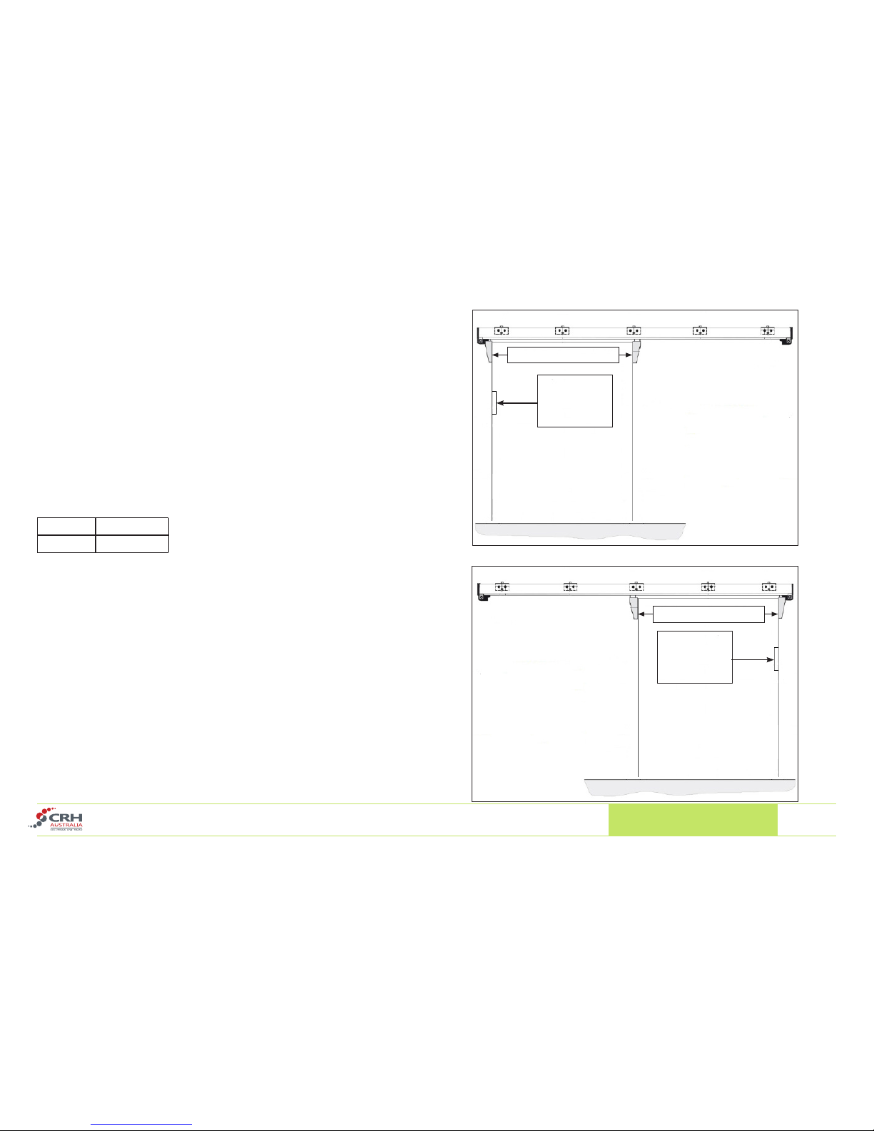
When the door is closed, tightness of the door against the frame is achieved by 2 rollers moving down the ramps and in against the door frame.
When the door is open, the 2 rollers come up the ramps and the door moves away from the oor & frame. This means that the door seals are
only in contact when the door is in a closed position. The rollers run eortlessly along the rail until they reach the end of the track stop.
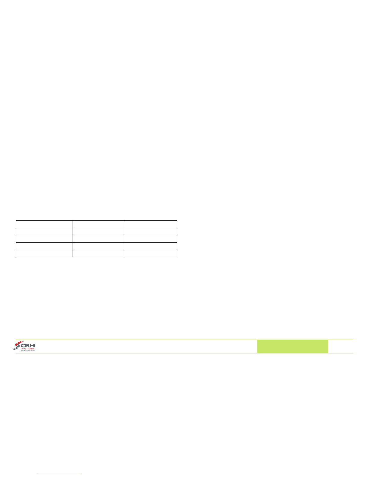
This system is suitable for doors within the following specications:
Specication Minimum Maximum
Door Blade Width 2001mm 2300mm
Door Blade Height - 2900mm
Door Blade Thickness 50mm 150mm
Door Weight - 120Kg
The operating temperature is between -30 °C and +55 °C.
The maximum noise level generated when the door operates is lower than 85dB.
The lever handle recommended for use with this system are as follows:
Internal Lever Handle :
F8530, F8530P (Packer)
External Lever Handle.
F8730-70/115K Used for door blades including gasket between 70mm and 115mm thick.
F8730-115/160K Used for door blades including gasket 115mm and 160mm thick.

Fermod Floor Guided Sliding Door Hardware Kits - F2156 Installation Guide www.crh.com.au
3
IMPORTANT INFORMATION
1. Due to the varying density of wall panel types used in Australia,
CRH Australia STRONGLY recommends that an aluminium
Support Rail is securely xed to the panel wall and then the Track
Rail Brackets are secured into or through the Support Rail.
2. The installation drawing that follows in these instructions are all
based on the fact that the Track Rail Brackets are Flush with the
face of the door frame, i.e. they are both oset the same distance
from the wall panel.
3. As the L shaped Track Rail Brackets need to be packed out the
same distance as the face of the door frame it is suggested that
the Support Rail also serves as the packer.
IMPORTANT- THE SUPPORT RAIL/PACKER MUST BE THE
SAME THICKNESS AS THE DOOR FRAME.
Support Rail / Packer
Track Rail
Trolley &
Roller
Gasket
Door Blade
Door Frame

Fermod Floor Guided Sliding Door Hardware Kits - F2156 Installation Guide www.crh.com.au
4
R+65
RR
R+70
20 70
120110
25
70
E+114
E+70
E+70
E+107
E
22X+2202
1/2X+104
1/3X-301941/3X-301/3X-30206
60
X50
R
==
LR
25
20
200
R’+84
65
89,5
R’
120
H
Y
E=50
mini
35
26
1/3X-30
1/3X-301/3X-30
X=Door Width
L=Clear opening width
R=Overlapping width
R’=Overlapping height
E=Door thickness
Y=Door height
H=Clear opening height
Z=Door Frame

Fermod Floor Guided Sliding Door Hardware Kits - F2156 Installation Guide www.crh.com.au
5
Ref Description
A1 Rail (1)
A2 Running Prole (1)
A3 Floor Guide Prole (1)
A4 Ramp (2)
A5 Running prole end clamp (2)
A6 Rail stop opening side (1)
A7 Rail stop closing side (1)
A8 Rail holder & screw (5) (3 for F2131)
A9 Rail holder
A10 Rail upper cover (1)
A11 Frame gasket (1)
A12 Frame gasket xing prole (3)
A13 Frame gasket corner prole (2)
A14 Floor gasket xing prole (1)
A15 Floor Gasket (1)
A16 Gasket xing bolt & nuts (Not Included in Kit)
A17 Floor Guide Opening Side (1)
A18 Floor Guide Closing Side (1)
A19 Roller + trolley RH
A20 Roller + trolley LH
A21 Door bracket/Door RH
A22 Door bracket/Door LH
A23 Trolley cover
A24 Complete roller assembly RH (1)
A25 Complete roller assembly LH (1)
A26 Rail end cap (2)
Components Supplied
What is NOT supplied in your Fermod Wall Guided Sliding Door Kit.
• Fasteners
• Aluminium Support Rail
• Sliding door blade.
• Door frame.
Required Fasteners (Not Supplied)
19 Screws or anchor bolts M8x40mm
4 Masonry Anchors 14G x 70mm
12 screws TR M5x30mm
50 to 100 TR M4x25mm

Fermod Floor Guided Sliding Door Hardware Kits - F2156 Installation Guide www.crh.com.au
6
Door Blade Construction
Each contractor may have their own method of insulated door
construction. The Fermod Floor Guided Hardware Kit does require metal
anchoring points to be constructed within the door blade that can be drilled
& tapped to secure key components such as:
• Left hand & right hand trolley assemblies.
• External Lever Handle.
It is recommended that the metal anchoring points are 10mm thick.
External Lever Handle anchoring - Recommended fastener height from the
bottom of the door:
Lower 1170mm
Upper 1240mm
Door size construction should also allow for the Fermod Gasket supplied
in the kit. F8511 Frame Gasket - 35mm Height, F250 Floor Gasket - 35mm
Height.
Lever Handle
anchoring
point
Right Hand Opening
Left Hand Opening
Lever Handle
anchoring
point
Trolley Assemblies
Trolley Assemblies

Fermod Floor Guided Sliding Door Hardware Kits - F2156 Installation Guide www.crh.com.au
7
Step 1.
Attach the frame gasket supplied to
the internal side of the door blade
using the xing strip & corners.
For negative temperature doors
purchase the “Negative Temperature
Kit” which will include the extra run of
frame gasket.
NOTE:
Negative temperature means
doors operating below zero
degrees celsius
Positive Temperature Conguration Negative Temperature Conguration
Inside Face of Door Blade

Fermod Floor Guided Sliding Door Hardware Kits - F2156 Installation Guide www.crh.com.au
8
Negative temperature oor
gasket conguration
Step 2.
Attach the oor gasket to the bottom of
the door blade.
Ensure to bolt through where the
frame & oor Gasket xing strips meet.
Nylon bolts are provided in the kit for
this purpose. (A16)
For negative temperature doors, 2
runs of oor gasket are recommended.
Purchase a “Negative Temperature Kit”
which will include the extra run of oor
gasket and xing prole.

Fermod Floor Guided Sliding Door Hardware Kits - F2156 Installation Guide www.crh.com.au
9
Step 3.
Cut the Floor Guide Rail to the correct
length.
DO NOT CUT THE GUIDE RAIL ON
THE CLOSING SIDE.
Once the guide rail has been cut to the
correct length le the sharp top corner
to a small smooth radius.
X= Total door blade width.
Example:
If the total door blade width
is 1600mm the cut oor
guide rail length is 1660mm.
X + 60
30 80 R 20
Opening
Side
Closing
Side

Fermod Floor Guided Sliding Door Hardware Kits - F2156 Installation Guide www.crh.com.au
10
15
20
200
200
30
X
Ø5
X+60
R20
Step 4.
Attach the oor guide rail to the front
face of the door blade.
Closing Side
Opening Side

Fermod Floor Guided Sliding Door Hardware Kits - F2156 Installation Guide www.crh.com.au
11
Step 5.
Mounting Holes for the hanging door brackets.
On the top left and right edges of the door blade drill and tap the xing
holes to attach the hanging brackets. Be mindful of the thickness of the
support rail packer you are using.
The support rail bracket should be the same thickness as your door frame,
if these are dierent you should adjust you hole locations accordingly. E.G
If you were to use a 15mm thick door frame & a 25mm thick aluminium
support rail prole the measurement would change from 20mm in from the
gasket to 30mm.
The measurements are also based on the use of the Fermod 35mm Frame
Gasket. Using a dierent gasket may require adjustment.
Note:
Be precise on your locations measuring from the inside of the door blade,
as there is little horizontal adjustment available on the hanging brackets.

Fermod Floor Guided Sliding Door Hardware Kits - F2156 Installation Guide www.crh.com.au
12
Step 6.
Cutting the main rail to length.
The main rail length must be double the door blade with plus an
additional 220mm.
“X” equals the total door blade width.
Example: If the total door blade width is 1600mm, the main rail
should be 3420mm. (1600 x 2 + 220).
Step 7.
Cutting the running prole to length.
2 x running proles cut to length are
required.
The running prole must be equal to the door blade width less
45mm.
“X” equals the total door blade width.
Example: If the total door blade width is 1600mm, 2 lengths need
to be cut at 1555mm. (1600 - 45)

Fermod Floor Guided Sliding Door Hardware Kits - F2156 Installation Guide www.crh.com.au
13
Step 8.
Assembly of the ramps, running prole and rail
stops.
Note. The drawing shows a left hand opening
door and should be reversed for a right hand
opening door.
• Slide the running prole, ramps and clamps into
the rail (see drawing for mounting order)
• Tighten the clamp/closing side. Clamp should
be ush with the end of the main rail.
• Opening side, push the clamp so all parts are in
contact and tighten.
• Slide the rail stops onto each end of the rail and
temporarily tighten.

Fermod Floor Guided Sliding Door Hardware Kits - F2156 Installation Guide www.crh.com.au
14
Quick Reference Tips.
• Make your aluminium support rail the same length as your main rail for simple calculations.
• Fix the rail holder brackets to the support rail in the workshop prior to going to site.We recommend that the brackets are xed using a bolt, nut &
washer combination. This can be achieved in the workshop by cutting or drilling holes in the back of the support rail to gain access with a socket.
The essential measurements:
• The bottom centre mounting hole on the closing side is 194mm from the end of the support rail.
• The bottom centre mounting holes on the opening side is to be 206mm from the end of the support rail.
• The centre rail holder bracket should be positioned half way between.
• Mark the centre of your clear doorway opening
• Calculate 1/2 the size of the door blade minus 90mm,eg. door blade 1030 ÷ 2 - 90mm = 425mm.
• Measure from the centre of the clear opening towards the closing side & mark.
• Calculate Door Blade overlapping height above the clear opening + 84mm. e.g Door overlap is 65mm + 84mm = 149mm.
• Measure up 149mm from the top of the clear opening & this is the location point of the bottom centre mounting hole.
• You can now locate your support rail holder brackets. Fix the support rail to the wall ensuring it is level.

Fermod Floor Guided Sliding Door Hardware Kits - F2156 Installation Guide www.crh.com.au
15
Step 10.
Mark and drill the xing holes for the rail brackets.
Top mounting holes
Bottom centre mounting hole
Step 10.
Attach the rail holder brackets to the support rail/wall.
It is recommended that the support rail sits on top of the door
frame to provide extra support.
Refer to drawing.
X=Door Blade width.
L= Clear opening width.
R’= Overlapping height (minimum 50mm) - (Y+32) - H.
Y = Door height.
H= Clear opening height.
60
1/3X-30
1/3X-30
30
60
30
60
30
60
60
30
30
L
1/3X-30
R’+84
26
Ø8
6
0
30
3
60
0
1/3X-30 1/3X-30
1/3X-3
0
1/2X-90
==
Closing Side
Opening Side

Fermod Floor Guided Sliding Door Hardware Kits - F2156 Installation Guide www.crh.com.au
16
Step 11.
Attach the main rail to the rail holder brackets.
1. Slide the 3 xing nuts into the main rail prole
and attached each using the bolts & washers
provided.
2. Adjust the end of the closing side to the
distance shown in g.B
3. Refer to drawing on page 3 for the distance
from the support rail to the face of the main rail,
(89.5mm).
4. Tighten the xing screws.
Note:
After hanging the door the installer may nd that
the top gasket is tight against the frame causing
the bottom of the door to be pushed outwards.
This will aect the performance of the door. In
this case, loosen the top bracket screws and
adjust the top rail outwards. Fig.B
CLOSING SIDE
Fig.AA9
A8
149

Fermod Floor Guided Sliding Door Hardware Kits - F2156 Installation Guide www.crh.com.au
17
Step 12.
Install closing & opening side oor guides.
E = Door blade thickness (excluding gasket).
Example: If door blade thickness is 75mm
the measurement out from the frame will be
112mm.
R = Overlapping width.
Example: If the door overlaps the frame 50mm
on each side the following measurements would
apply.
Fig.a R - 46 = 4mm
Fig.b R + 1 = 51mm
Note: If xing through oor tiles drill a 5mm pilot
hole before inserting the Masonary Anchors
other wise you may damage the tile.
Closing Side Opening Side
Door Frame Door Frame
Fig.a Fig.b

Fermod Floor Guided Sliding Door Hardware Kits - F2156 Installation Guide www.crh.com.au
18
Step 13.
Install the door brackets on the main rail and running
prole. Install each door bracket from the centre ramp
and slide to the left & right.
Step 14.
Attach the door brackets to the door blade.
1. Wedge Up the door blade & bolt/screw the door
brackets into the previously pre-drilled & tapped
holes.
Step 15 - Adjust the door.
1. With the door in the closed position, the oor and
frame gaskets should create a rm seal, however the
gaskets should not be squashed and out of shape. If
the seal at the top of the door is too tight it will push
the bottom out and guides will not run smoothly.
2. When the door is running, the gaskets should not
touch the frame or oor.
3. Height adjustment can be achieved by adjusting
the door brackets as shown.
4. Tightness against the frame can be adjusted by
adjusting the oor guide. See Fig A & B on the next
page.
5. Loosen A for horizontal adjustment then tighten.
±11
B
C
A
A19A20
A22A21
A23
A25A24
D= Right Hand Side
G= Left Hand Side
G
D
TO ADJUST DOOR:
Loosen screws C 1/2 turn.
Tighten or loosen screw B
Lock screw C
Wedge 20mm

Fermod Floor Guided Sliding Door Hardware Kits - F2156 Installation Guide www.crh.com.au
19
Step 15 (Continued)
Adjust the door.
Fig.A. Opening side oor guide in the open position.
The guide allows for 7mm +/- adjustment.
Fig.B. Closing side oor guide in the closed position
Fig.A
Fig.B
Gasket
Gasket
(Sealed but not
squashed)

Fermod Floor Guided Sliding Door Hardware Kits - F2156 Installation Guide www.crh.com.au
20
Step 16.
Attach the trolley covers.
To attach push in and straight up. To remove slide straight down.
Note: Take care with the trolley covers as the plastic lugs are easily broken if
forced the wrong way
Step 17.
Attach the nal covers.
1. Cut to size and attach the rail upper cover (A10). This is a dirt and hygiene
protection feature
2. Attach the 2 x rail end covers. (A26)
1
2A10
Table of contents
Popular Garage Door Opener manuals by other brands

Chamberlain
Chamberlain 995XD owner's manual

Centurion
Centurion Vantage installation manual

GFA
GFA ELEKTROMAT SI 8.20-25,00 10003369 10011 installation instructions

Chamberlain
Chamberlain Whisper Drive WD922K owner's manual

Chamberlain
Chamberlain Dial Code installation manual

Chamberlain
Chamberlain Series 1000E owner's manual

SOMFY
SOMFY Dexxo Pro 800 RTS Installation manual - Illustrations

Chamberlain
Chamberlain PD432DM 1/2 HP Owners owner's manual

Aprimatic
Aprimatic ROLLI Series Installation and adjustment instructions

Genie
Genie Intelligent Wall Console manual

Becker
Becker BOM 520 operating instructions

Beninca
Beninca KEN3 Operating instructions and spare parts catalogue