Crime Guard 650i6 User manual

Modular
Backup
Battery
Valet Switch
plugs
in
inside control module
Inside Control
Module:
Backup Battery
plugs
in
and mounts
System Antenna
~
Jumper
~PIUg
2-way Echo can be
added, as
an
option
Programmable Relays
"Unlock"
Relay
(programmable) Cables
(+)
or
(-) Input (N/O) -VioletlBlack
Output (COM) -BluelBlack
Input (N/C) -Brown/Black
--
.....
"Lock"
Relay
(programmable) Cables
(+
or -) Input (N/O) -BlacklRed
__
----I
Output (COM) -GreenlViolet
.....
Input (N/C) -White/Red
---'
Page
-19
\650i6
\\\\\\\\
DLS Power Doorlock
Interface Port
Lock Output -Green
Relay Coil Power (pin)
Unlock
#1
Output -Blue
Unlock #2 Output -Pink
./
Auxiliary
Selsor
Port
#1
!
Auxiliary Sensor Port
#2
(
System
Receive ITransmit
Module
Valet
Switch
Status Lights
Page
-18
Power -
Red---./
Ground -
Black---/
Trigger -
Blue-----"
Prewarn -
Green-----"
Secondary Wiring Harness Connector
(-) 3rd Channel Output -Pink
(-) Door Trigger Input -Green
(-) Hood Trigger Input -Blue
(+) Door Trigger Input -Violet
(+) Siren Output -Brown
(+) Parking Light Output -White
Interior Light Output -GreenlViolet
(+
or
-) Interior Light Input -BlacklRed
Main Wiring Harness Connector
(-) Starter Interrupt Output -Orange
-------------~
(-) 2nd Channel Output (trunk release) -Gray
====-_----==::=::j
Ignition Power Input -Yellow
:=~~
System (-) Ground -Black
To
Constant
(+)
Power -Red
Wiring
Diagram
Overview
The Crime Guard 750i6
is
a2-way secu-
rity
system,
which
includes
a
I-way
transmitter and a2-way controller. The
650i6
is
aI-way system, including two
transmitters.
The
650i
6may
be
up-
graded to 2-way operation by an
op-
tional
Omega
Echo kit.


Contents
Wiring Diagram Overview 18-19
Installation Considerations 3-5
Wiring Connections
Main Wiring Harness 6-8
Secondary Wiring Harness 9-17
Auxiliary Harness &Programmable Relays 14-16
Accessory
Connections
DLS
Power
Doorlock Port.. 17, 20-22
Backup Battery 23
Dual Sensor Ports 23
Data Port 23
Programming
The Programmable Features 24-32
Progran1ming Features 33
Programmable Features Matrix 34
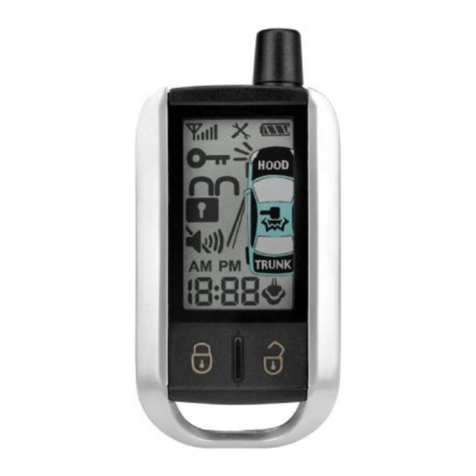
The Crime Guard 650i6'stransmitters and the 750i6'sI-way transmitter and
2-way controller are pre-programmed at the factory to operate the system.
If
adding
or
replacing transmitters orcontrollers, please see the Operation
Guide booklet for Transmitter and Controller programming.
Omega
Disclaims Any Responsibility or Liability
In
Connection With Installation.
Copyright2009 Omega Research and Development, Inc.

-
IMPORTANT-
Please carefully read these instructions before
starting
the installation
of
the Crime
Guard
security
system.
The
numerous
wiring
connections required,
and
the options offered
by
several
of
the programmable features makes
pre-planning the installation critical.
More complete instructions for programming
transmitters
and
features
may
be found in the
Operation Manual.
Installation Considerations
Before Starting The Installation: This entire booklet should be read
before starting the installation. An understanding
of
which control module wires
are to be used and theirfunctions is essential. Installations will vary from car to car
,as some control module wire connections are required, while others are optional.
Before starting the installation, it should be determined which control module
wires will be used. Most installers will list these wires, then "map out" the instal-
lation by locating and noting the target wires in the vehicle. This will also deter-
mine the best location for the control module, which is mounted upon completion
of
the installation and testing
of
the system.
Some
of
the wiring connections, such as power, ignition and starter interrupt, are
best made at the ignition switch harness, located around the steering column area.
CAUTION! Avoid the Airbag circuit! Especially avoid any har-
ness or wires encased
in
Yellow or Red tubing or sleeves. Do not
use astandard test light, as
it
can deploy an airbag or damage
on-board computers and sensors if the wrong circuits are probed.
ADigital Multimeter (DMM) should be used.
Other typical connection points may be behind the dash or in the kick panel areas,
for parking and/or interior lights, trigger circuits and power doorlocks. Soldering
or proper use
of
crimping terminals for all wiring connections are recommended.
Page - 3

Mounting The Control Module: The Control Module contains the
necessary electronics required for the system's operation. Always mount this mod-
ule
in
the vehicle's interior compartment,
in
asecure location that is not easily
accessible. Ensure that moisture, vibration and temperature extremes are mini-
mized. Acceptable locations include mounting behind the dash, behind the glovebox
or other interior panels.
Mounting The Electronic Siren: The electronic "2-n-1 Psycho Siren"
must be mounted external
to
the vehicle, but not accessible or vulnerable to tam-
pering. The engine compartment typically offers the best mounting location op-
portunities. See page 9for specific mounting and connection details.
The Status Light and Valet Switch are in two forms:
-contained within the 2-way transceiver unit, as with the 7S0i6;
-and as separate items, which can be mounted independently or in acombination
holder, as with the 6S0i6•
The separate Status Light and Valet Switch may be used with the 7S0i6as optional
parts, and the transceiver unit hidden,
if
desired; and similarly the
6S0i
6may
be
upgraded to 2-way operation, which adds the transceiver to the system. It
is
im-
portant to understand this flexible compatibility, both ways, between the two se-
curity systems, and with the two forms
of
Status Light and Valet Switch.
Transceiver- Using the transceiver-mounted items requires no special in-
stallation considerations; this places the Status Light in agood position to be seen,
both inside and outside
of
the vehicle, and the Valet Switch at aconvenient loca-
tion
to
the user. The user may customize the switch presses required to perform an
Emergency Override with Programmable Feature
#1
(the factory setting is the
most
convenient"
1press").
The transceiver unit may be mounted directly to an interior glass by utilizing
the attached adhesive pad (clean and prepare the glass before adhering). The best
operating range performance is obtained by mounting the transceiver placed as
high as possible in the vehicle, with the smaller rod-like end pointed upwards.
Avoid mounting this unit close to metal parts or structure
of
the vehicle.
Separate- In the case
of
the 6S0i6,or as optional parts for the 7S0i6,the
separate Status Light and Valet Switch may be custom-mounted inside the vehicle
by drilling a 9 I32" hole in asuitable interior panel;
be
sure to carefully ensure that
the area behind the location has an unobstructed depth
of
at least 1/2". Then route
the wiring harness through the hole to the control module, and snap the light in
place. Mount the valet switch, using its adhesive pad, in ahidden location which
is
accessible to the operator; carefully route the wires to the control module.
Or, use the combination holder for the Status Light and Valet Switch. Mount
the assembly in alocation where it can easily be seen by the driver, and preferably
where it can be seen from outside. Two mounting methods are provided: double-
Page - 4

sided adhesive tape, and two screws.
If
using the adhesive tape, properly prepare
the mounting surfaces to ensure good adhesion.
If
using the screws for amore
permanent mounting, carefully separate the housing halves, install the screws
(avoid overtightening), then snap the assembly halves back together. Carefully
route the wiring harness to the control module to avoid any chances
of
it being
chafed
or
pinched.
Power DoorlockOptions: The unique flexibility
of
the 750i6and 650i6
is also found in multiple options for interfacing the vehicle power doorlocks.
Internal Relays- Both models feature internalrelays, whichare programmable
for several differentfunctions. Thee default settings are "lock" and "unlock", with
optional operations consisting
of
parking light, horn,
or
two additional remote
channels, as latching
or
on demand. Relays are not always needed for doorlock
connection, and the following two options offer further flexibility that the internal
relays can be available for optional functions.
DLS Port- The second option is the traditional
"DLS"
port, which can accept
all Omegaanalog doorlockingaccessories (dual, triplerelay sockets, orthe modular
clip-onadd-onrelay packs)and direct-wirebasic 3-wireNegativepulsedoorlocking
systems. All Omega doorlocking data bus module accessories can be driven by
eitherthis port, and the DLS portoffers two unlocking outputs, so that driver's door
priority unlocking can be configured.
Data Port for IntelliKit Modules &Bypasses:
Omega
IntelliKit data bus
interface modules and bypass kits simply plug into this port. These data-to-data
(D2D) accessory products save time, and in many cases offer the only acceptable
interfacemeans for many newer vehicle's doorlocking system and/orfor the OEM-
antitheft bypass when adding an alarmoran optionalaccessory remote start module
with the Crime Guard. Omega offers the industries most comprehensive line
of
these products (go to www.caralarm.com for latest application guide), and each
includes its own vehicle-specific instructions.
Backup Battery: Both models have backup battery capability. Included
are the 9volt battery, the wiring harness and slide-on clip mounting bracket.
If
the
system loses vehicle powerit will revert to operating with basic security functions,
if
the backup battery is installed.
Dual Auxiliary Sensor Ports: Both models also feature two auxiliary
sensorports.
The
includedimpactsensorplugs into oneport, and the second allows
the easy addition
of
afurther optional sensor. Each
of
the ports is dual-zoned: the
first zone will respond by chirping the siren only; and the second zone will fully
triggerthe system, and bothhaveidentical layout and operation. Theincludedglass
breakage and dual-zone impact sensor is packaged with its own instruction sheet,
as are all
of
the optional Omega sensors which can be further added.
Page - 5

Wiring Connections
-NOTE -
The
following
sections
detail
connections
for
each wire, of
each
system's
wiring harnesses.
Always
insure
that
the
Black
ground
wire is grounded, and
that
the
secondary
wiring
harness
is plugged in,
before
connecting
power
circuits
to
the
control module. The best
installation
proce-
dure
is
to
make all
connections,
and
only
then plug the
individual wiring harnesses into the system control module.
Main Wiring Harness
(5-Wire Connector)
Black Wire -(Ground): The Black wire provides Negative ground for
the system; proper connection
of
this wire is very important.
CONNECTION: Using the correctly sized crimp-onring terminal, connectthe
Black wire to the metal frame
of
the vehicle, preferably using an existing machine-
threaded fastener. Make sure that the ring terminal attached to the Black wire has
contact with bright, clean metal.
If
necessary, scrape any paint, rust orgrease away
from the connection point until the metal is bright and clean.
If
the control module
has an insufficient ground connection, the security system can find partial ground
through the wires that are connected to other circuits, and function, but not
correctly. As the system can partially operate, abad ground wire connection would
not likely be suspected, and in many cases apoor ground is difficult to diagnose.
Red Wire -(Constant Power Input): The Red wire's function
is
to
supply Constant Positive
12
Volts for security system's operation. When
12
Volts
is first applied to the Red wire, the system will revert to the state in which it was in
when power was taken away.
If
the vehicle to be serviced, especially
if
it involves
thebattery, the systemshould beplaced in ValetMode. This will preventthe system
from being activated ifthe battery is disconnected and reconnected.
The
Red wire
also supplies
12
Volt Positive to the module's internal relay for flashing the parking
lights.
CONNECTION: Connect the Red wire to aConstant Positive
12
Volt source.
This sourceshouldhave Positive
12
Volts withat leasta
15
Amp
capacityatall times
and in all ignition key positions. Connection locations can be at the supply wire at
Page - 6

the ignition switch, the supply wire behindthe fuse block
or
the fuse/junction block.
Neverjustinsert the Redwire orany othersecurity system wire behind afuse. Also,
please note that connecting directly to the battery's Positive terminal will expose
this connection to failure due to acorrosive environment unless the connection has
aprotective coating.
Yellow Wire -(Ignition Input): The Yellow wire is an ignition "on"
input to the security system. This connection is critical to the proper operation
of
many
of
the security system's features.
CONNECTION: This wire supplies Positive
12
Volts to the control module
whenever the ignition switch is "on". This connection should be made at the
ignition switchharness, to the primary ignition circuit. Primary ignition has 0Volts
when the ignition key is in the "Lock", "Off" and "Accessory" positions; and
Positive
12
Volts in the "Run" and "Start" positions. Locate the correct wire at the
ignition switch harness and securely splice the Yellow wire to it.
Orange Wire -(Negative Output While Armed); Includes the
thick Red &White Wires attached to the relay socket -(Starter
Interrupt): The Orange wire is astarter interrupt output, which is active when
the security system is in an armed state; the relay that it is attached to the Orange
wire prevents the starter from engaging,
if
astarting attempt is made while the
system is armed.
CONNECTION: The typical starter interrupt
is
shown here-
Socket
Orange
WIre
Starter Disable White
wire to the
Starter Solenoid
side
of
the cut
Starter Disable Red
wire to the Ignition
Switch side
of
the
cut wire.
Dash-
mounted
Ignition
Switch
Starter Disable
Connections
Page
-7

Thestarterwire must be located and cut. Cutting the vehicle's starterwire will result
in
two sides- the "ignition switch" side and the "starter solenoid" side.
It
is
recommended that this connection be done as close to the ignition switch as
possible. Use aDigital Multimeter (DMM) to find the correct wire.
CAUTION! Avoid the Airbag circuit! Especially avoid any har-
ness or wires encased
in
Yellow or Red tubing or sleeves. Do not
use astandard test light, as
it
can deploy an airbag or damage
on-board computers and sensors if the wrong circuits are probed.
ADigital Multimeter (DMM) should
be
used.
The starter wire will read Positive
12
Volts only when ignition key is in "start"
position (cranking the engine). Cut this wire at asuitable location. Confirm that
this is the correct wire by turning the ignition switch to the "start" position; the
starter should not engage.
Connect the starter disable socket's Red wire to the ignition switch side. Con-
nect the starter disable socket's White wire to the starter solenoid side. Be sure
that good, solid electrical connections are made.
Gray Wire -(2nd Channel or Negative Trunk Release Out-
put): The Gray wire is an optional output operated by the controller/transmitter
"II"
button; typically the primary use is for trunk release.
CONNECTION:
If
the vehicle's existing trunk release switch operates as
switching Negative to activate trunk release, and draws 250mA
or
less, the Gray
wire may connected directly
to
the vehicle's switch output wire.
If
the target wire
is Positive switching, and/or draws more than 250mA, an optional relay must be
used.
To
configure arelay to the Gray wire, connect it to relay pin (85), and
connect Constant Positive
12
Volts to relay pin (86). Connect pin (30) to power,
or ground, as needed. Pin (87) is then connected to the vehicle's trunk wire.
Page - 8

Secondary
Wiring
Harness
(B-Wire Connector)
Brown Wire -(Positive Siren Output): The Brown wire is a 1 Amp
Positive output designed to operate the electronic siren for audible confirmations,
and to sound
if
the alarm is triggered.
SIREN CONNECTION: The Brown wire may be connected directly to the
siren's Red wire, and the siren's Black wire is connected to (-) Ground.
SIREN MOUNTING: Findalocation in the enginecompartmentaway from the
extreme heat
of
the engine and manifold. Asuitable location will offer afirm
mounting surface, will also allow sound dispersion out
of
the engine compartment,
and not be accessible to athief. The siren must be pointed downward to avoid
moisture getting inside it and to enhance sound dispersal.
SIREN CHIRPS: The siren itselfcan be set for loud or less loud confirmation
chirps- cut the short Black wire loop on the siren for louder confirmation chirps.
The confirmation chirps volume may also be adjusted to four different volume
levels by User Programmable Feature #10. User Programmable Feature #9 turns
the chirps
off
completely, orit can also set the system to only chirps in valet mode,
or
to chirp except when the system is in valet mode.
HORN CONNECTION: Both Crime Guard models can sound the vehicle's
existinghorn in addition to,
or
in placeof, the electronic siren. Soundingthe horn
is accomplished by one
of
the programmable relays; see pages 14-16.
White Wire -(Positive Flashing Light Output): This is aPositive
12
Volt output to flash the vehicle's parking lights for visual arming confirmation,
to illuminate them for disarming confirmation, to confirm remote starting, and to
attract attention while the system is activated.
CONNECTION: Connect this wire to the vehicle's Positive 12 Volt parking
light circuit, which can usually be found at the following locations: at the headlight
switch, at the fuse/junction block, or in the rear body harness in the driver kick
panel. Some vehicles have aparking light relay which is triggered by aNegative
Ground circuit from the headlight switch; for these vehicles, simply find the
Positive output side
of
the stock relay for adirect connection; or, use the internal
programmable relay for "parking light", wire the relay Negative (page 16), and a
direct connection to the vehicle's Negative parking light wire may be made (in this
case the White wire would not be used).
The correct wire will show Positive
12
Volts when the headlight switch is in the
"Parking Light" and "Head Light" positions. When such awire is located, also test
Page - 9

to ensure that it
is
non-rheostated: meter the wire operate the dash light dimmer
control; the correct wire will show no voltage change when the dimmeris operated.
Do
not
connect
the
White wire
to
arheostated
(dimmer)
circuit!
This will backfeed the parking lights through the rheostat or illumination
control module, and possibly cause damage to the vehicle or security
system control unit. Flashing the headlights is not recommended.
Another
cautionary
note is that the halogen headlights found in modern vehicles
are not designed to be rapidly turned on and off, and
if
connected to the security
system, areduction
of
their useful life may be occur.
If
flashing the headlights is
still desired, arelay must be used, since the headlight's current draw exceeds the 10
amp rating
of
thebuilt-in relay.
If
flashing headlights and parking lights aredesired,
use two relays -configure one relay to supply the parking lights and the otherrelay
to supply the headlights.
Parking
Lights
White
Dimmer
Junction
Block
Dash Lights
Parking
Lights
Caution:
Do
not connect to the
dimmer
circuit!
Damage can occur to the unit &
the
vehicle.
Recommended Connection Points For The White Wire
OTHER
PARKING
LIGHTCONNECTIONS:
BothCrimeGuardmodelscan
use one
of
the programmable relays in conjunction with the White wire to flash
both sides
of
dual-parking lightvehicles. And as described on the previous page,
the programmable relay can be configured and wired to operate aNegative
parking light circuit. See pages 14-16 for programmable relay options.
Page -10

Green Wire -(Negative Door Trigger): The Green wire is an "open
door" input to the control module for vehicles having Negative switching door pin
switches. This wire is most commonly connected to the vehicle interior light
system. Typical Negative Switching Interior Light System
Interior Light
(+)12 Volts
-Cf)
a~
~
Ef/
This is the
correct "trigger"
wire -connection
may be made at
Driver any point Passenger
Pin
n=:g.t::::==:!....---------..:~--..----_c::«~D=::(J
Pin
Switch Switch
The Driver Pin Switch will often have
an extra wire that activates the "ignition
key in switch" warning chime. This
circuit will activate the security system,
but only from the driver's door, and is
the incorrect trigger wire >
CONNECTION: Connect the Green wire to awire in the vehicle that
is
common to all the doorpin switches; the correct wire in this type
of
interior
or
dome
light/door
jamb
pin switch system will have no voltage present and will also show
chassis ground when the doors are opened, and up to
12
volts when the doors are
closed.
Violet Wire -(Positive DoorTrigger): The Violet wire is identical to
the Green Door Trigger wire, with the sale exception that it
is
an open door input
to the control module for vehicles having Positive 12 volt door pin switches.
Typical Positive Switching Interior Light System
Note: The Driver Pin Switch
will often have an extra wire;
this circuit will activate the se-
curity system, but only from the
driver's door. This is the incor-
rect activation
wire>
Driver
Pin
Switch
This is
the correct
"trigger" wire
-connection
may be made at
any
point~
Interior
Light
To Chassis
~--~
Ground Passenger
Pin
Switch
+To Constant
'------4
12 Volt
Page
-11

The correct wire for aPositive switching type
of
dome light/door
jamb
pin
switch system will have
12
volts present when the doors are opened, and chassis
ground when the doors are closed.
CONNECTION: Connect the Violet wire to awire in the vehicle that
is
common to all the door pin switches; the correct wire for this type
of
dome light/
door
jamb
pin switch system will have
12
volts present when the doors are opened,
and chassis ground when the doors are closed.
Notes and Tips, both
types
of
Interior
Light
or
Door
Trigger
circuits:
The correct wire will show this change when any
of
the doors are
opened.
If
the vehicle has delay-off
or
"fade away" interior lights, remember
to take this into account when testing the wire.
If
the pin switch is mounted
in the metal structure
of
the vehicle, and the interiorlighting goes out when the
switch is removed, suspect agrounding switch-type lighting system.
Switches controlling interior lighting may be found in several locations-
the front or rear door
jamb
area, as the traditional "pin switch" or sliding
switch; or as switches inside the doors, either connected to the exterior door
handles or to the latching mechanism. Avehicle which has the interior lights
illuminating when the outside door handle is lifted is an example
of
this type
of
switching system.
Also be aware
of
vehicles which diode-isolate each door. Typically, this
is usually encountered with dash displays that indicate individual doors being
ajar. The proper wire to connect to in this type
of
system
is
the common wire
which is routed directly to an interior light that illuminates when any door is
opened.
GreenNiolet
-(Domelight
Supervision
Output) &
Black/Red -(Domelight Supervision
Input)
Wires:
Domelight Supervision offers an additional safety and security feature- upon
disarming the system the interior lights will turn
on
to illuminate the interior. The
GreenlViolet wire is the output to turn on the lights, and the Black/Red wire is
input, connected to Positive or Negative polarity which is needed for operating the
interior light.
CONNECTION GREENNIOLET: The proper vehicle wire
to
connect the
Green/Violet wire to, the dome light activation wire, is common to all the door pin
switches. The correct wire will change polarity as the doors are opened and closed.
The dome light activation wire in the vehicle is typically the same wire
that
the
Green
or
Violet wire is connected to, for
the
door
trigger.
Page -12

For reference, see the diagrams on the previous page
11
showing the basic
differences between Negative and Positive interior light circuits.
If
the vehicle uses aNegativeswitching interior lightsystem, the activation wire
will have no voltage present and show chassis ground when the doors are opened,
and up to
12
volts when the doors are closed. The correct wire for aPositive
switching type
of
interior light/door
jamb
pin switch system will have
12
volts
present when the doors are opened, and chassis ground when the doors are closed.
Thecorrect wire will show these changes when any
of
the doors are opened.
If
the
vehicle has delay dome lights, remember to take this into account when testing.
CONNECTION BLACK/RED: The polarity
of
the dome light supervision
output must be selected by the connection
of
the Black/Red wire as Positive
or
Negative. Connection
of
the
GreenNiolet
should have determined which polarity
the vehicle uses to operate the dome light; this
is
either "Negative switching" or
"Positive switching" (see the diagrams on page 11). Once "Positive switching" or
"Negativeswitching"has beendetermined, connecttheBlack/Redwire to Negative
(for "Negative switching" interior lights)
or
to Positive (for "Positive switching"
interior lights).
Blue Wire -(Negative Instant Trigger): The Blue wire is aNegative
instant trigger used to detect entry into the hood or trunk area
of
avehicle.
CONNECTION: The included pin switches may be installed to provide this
trigger circuit; or,
if
there are existing switches the Blue wire may be connected
directly, provided this is anegative ground switching circuit (examples: an OEM
antitheft hood switch, or in the case
of
the trunk or hatch alight in the luggage
compartment or a"Trunk Ajar" light in the dash).
An indication
of
such acircuit
is
the wire having no voltage present when the
hood ortrunk is open, and up to
12
volts when the hood
or
trunk is closed. This wire
may be used with amercury type
of
tilt switch, by itself, but it cannot be used with
existing hood or trunk lights which have an internal mercury switch.
If
the vehicle
is equipped with ausable trunk or hood circuit, locate the proper wire and splice the
Blue wire directly to the vehicle's wire.
If
not, then you can install apin
or
mercury
switch and carefully adjust and test
it.
Multiple use of the Blue wire: When wiring more than one
of
the vehicle's
circuits and/or additional circuits to this wire, diode-isolation is usually required to
maintain each circuit's properindependent operation.
An
example would be wiring
ahood pin switch and trunk light switch together. Without isolating, the trunk light
will turn illuminate wheneverthe hood is raised. Also, diode-isolation
is
necessary
when combining electronic sensors together, or when adding asensor in the same
circuit as the pin switches. Page
-13

Diode-Isolating Multiple Negative Instant Triggers
Optional
Electronic
Sensor
Hood
Pin
Switch
Trunk
Pin
Switch
Trunk
Light
Blue (-) Instant Trigger Wire.
Use IN4002 Diodes to isolate
each switch or device
Pink Wire -(Negative 3rd Channel or Option Output): The 3rd
Channel Pink wire
is
an optional output similar to the 2nd Channel Gray trunk or
hatchrelease wire; however, this outputis not capable
of
disarmingthe systemwhen
it is used and therefore has no audible or visual confirmation.
CONNECTION: For most applications an optional relay will be needed;
typical connection
is
the Pink wire to relay pin #85, and connect Constant Positive
12 Volts to relay pin#86. Connectpin #30 to power,
or
ground, as needed. Pin #87
is the output, and connected to the target wire.
Auxiliary
Wiring
Harness
-
Programmable
Internal
Relays
(6-Wire
Connector)
Aunique feature
of
Crime Guard 750i6and the 650i6is two built-in singlepole,
double throw (SPDT) relays, which are programmable for several types
of
opera-
tion. These relays which offer the installer great installation flexibility. Each relay
is
externally wired with anormally-closed load input wire (N/C or "87a"); a
common load output wire (COM or "30"); and anormally open (N/O or "87")
wire which switches to the COM wire when the relay is activated. These program
Page -14

mabIe relay wires are an additional secondary harness, in the form
of
a6-wire
connector; each
of
the relays' 3wires are agenerous length
of
joined ribbon wire,
for ease
of
installation. The default setting, and functions
of
the programmable
relays are Door Lock and Unlock. Other functions are available, via the Program-
mable features #23 and #24,
as
shown here:
Programmable Feature Default 1st option
#23
Lock
Relay
Functions
Lock
(L)
Parking
Light
(U)
#24
Unlock
Relay
Functions
Unlock
(L)
Horn
Med.
(U)
2nd option
Ch
4
Latch
(2)
Ch
5
Latch
(2)
3rd option
Ch
4
On
Demand
(3)
Ch
5
On
Demand
(3)
The features may be programmed by turning the ignition on, off, then pressing
the Valet Switch 5times (producing asteady Status Light), and then pressing the
Valet Switch
23
or24 times more to select either feature. Settings are then changed
by pressing the controller/transmitter buttons
as
indicated above after each option.
CONNECTIONS: Using the Programmable Relays The defaulted
and optional uses
of
these relays are described in the following diagrams.
Relays' Default Settings
#23
"Lock"
Relay Ribbon Cable -setting
"LOCK"
N/O, 87)
Black/Red
+or - : likely +; see notes
COM, 30) GreenIViole
Output
to car "lock" wire*
N/C, 87a)
WhitelRed
Input
needed
if
reversal*
*see notes
#24
"Unlock"
Relay Ribbon Cable -setting "UNLOCK"
N/O, 87) VioletIBlack +or - : likely +; see notes
COM, 30) BluelBlack Output
to
car "unlock" wire*
N/C, 87a)
BrownIBlack
Input: needed
if
reversal*
*see notes
Notes- Use the "DLS" doorlock output port for "3 Wire Negative
Pulse" systems. These relays are perfect for "3 Wire Positive Pulse"
and "5 Wire Reversal" systems. If 3Wire Positive, connect both relay
N/O wires to Positive; relay N/C wires are not used.
If
5Wire Reversal system, connect
both N/O wires to Positive; connect relay N/C wires to the doorlock switch side, connect
relay
COM
to the actuators side. See the section "Power Doorlock Interface Port",
explaining the DLS port operation, for more doorlocking system information.
Do
not
exceed 10
Amps
current
draw-
systems drawing more will need external re-
lays, driven by the DLS port. Relay
"Lock"
and
"Unlock"
settings
exactly
imitates all
of
the DLS
port
doorlocking
operations,
but
only
the DLS
po
can perform
driver
door
unlock
priority
as
it
has
two
unlock
outputs.
FEATURES #23 and #24 ARE INDEPENDENTLY programmable -
the installer may set each feature as desired
or
needed.
Page
-15
more diagrams, next page

Relays' 1
st
Optional
Settings
#23
"Lock"
Relay Ribbon Cable -
option
"Parking
Light"
N/O, 87) BlackIRed +or - : as needed
COM, 30) GreenIViole Output: to parking light wire
N/C, 87a) WhitelRed Input: not typically used
#24
"Unlock"
Relay Ribbon Cable -
option
"Horn"
N/O, 87) VioletIBlack +or - : as needed
COM, 30) Blue/Black! Output: to vehicle hom wire
N/C, 87a) BrownIBlack Input: not used
Notes- Parking light circuits can be found as Positive or Negative,
although Positive
is
more common.
Hom
connections typically switch Nega-
Mtive; if found as Positive, do not exceed 10 Amps load.
"Parking
Light"
setting operates same as
the
White wire.
"Horn"
setting
operates the same as the siren, except as
pulsed
output
instead
of
steady.
FEATURES #23 and #24 ARE INDEPENDENTLY
programmable-
the
installer
may set each feature as desired
or
needed.
Relays' 2nd and 3rd Optional
Settings
#23
"Lock"
Relay Ribbon Cable -
option
"Channel
4"
N/O, 87) BlackIRed +or - ; see notes
COM, 30) GreenIViolet Output:
to
optional device
N/C, 87a) WhitelRed Input: most likely unneeded
#24
"Unlock"
Relay Ribbon Cable -
option
"Channel
5"
N/O, 87) Violet/Black +or - ; see notes
COM, 30) Blue/Black! Output: to optional device
N/C, 87a) BrownIBlack Input: most likely unneeded
Notes- These "Channel
4"
and "Channel
5"
outputs are similar to the
Gray wire 2nd channel (trunk release, which can also disarm) and Pink
wire 3rd channel outputs- they are additional remotely-operable outputs.
Operation: When either relay is programmed to operate as remote out-
puts, pressing the controller/transmitter buttons "arm/lock (A)" and "II" (2) together oper-
ates Channel 4; and pressing the "disarm/unlock (U)" and "III" (3) buttons together oper-
ates Channel 4(Feature
#21
can reassign the buttons).
"On
Demand" operation has the
output (either channel 4or channel 5) occur only while the controller/transmitter buttons
are being pressed;
"Latch"
toggles the output- one press
of
the two buttons turns on the
output, and another press
of
the buttons turns it off. Use caution,
or
rather
common
sense, when configuring either output for the Latch setting, as each relay draws 65mA
when activated. Leaving arelay
in
the activated condition for an extended period
of
time
would create an unacceptable current draw, or battery drain, on the vehicle.
Page -16

Accessory
Wiring Harness -
DLS
Port
(Red 4-Pin Connector)
The Crime Guard 650i5and 750i5both have great installation flexibility
when interfacing
it
to the vehicle's power doorlocking system.
On both models the internal programmable relays may
be
used
in
their defaulted settings as doorlock relays.
This Red DLS port can
be
directly connected to 3Wire Negative
doorlocking systems, or optional interfaces such as the DLS and 2
relays, DLR-C, DLR-U orothers will
be
needed for othertypes of power
doorlocking systems. Omega also offers other specialty doorlocking
interfaces; all include their own detailed instructions.
This section describesthe Red DLS port, and doorlock connections
with the included harness and optional interfaces.
Plug-In DLS Power Doorlock Interface Port: The Red 4pin port on the
system's control module produces anegative pulse output for locking the doors, a
constant 12 volt pin
for
the optional relay coils only, afirst negative pulse output
for driver door unlock, and asecond negative pulse output for unlocking all other
doors.
The vast majority
of
power doorlocks are found as three system types: 3wire
negativepulse, 3wire positivepulse and 5wire reversal, restatground. Otherpower
doorlock systems which may be encountered are the vacuum pump types found
in
older Mercedes vehicles and the single wire, dual-voltage which has appeared in
some late model vehicles. The best way to identify adoorlock systemis to examine
the doorlock switch's wiring.
3Wire Negative Pulse Systems are typically indicated by the presence
of
three wires at the switch.
Of
these, one will show constant ground, regardless
of
whetherthe switch is beingoperated ornot (at rest);
one
will show ground when the
switch is pushed to the "lock" position, and the other wire will show ground when
the switchis pushedto the "unlock" position. With the switch atrest, these two wires
will read voltage, usually
12
volt positive butin somecases less. The wires from the
switches operate doorlock relays or adoorlock control unit with built-in relays;
make the connections between the switches and the relays.
CONNECTION: Theincluded harness (DLP-N4) can allow direct connection
between the security system and a3-Wire Negative Pulse system.
If
more than the
500mA Ground output that the security module can provide is required, use the
optional model DLS and two relays. When driver's door unlock priority is desired,
use the optional DLS-3. Page
-17

Wiring
Diagram
Overview
The
Crime Guard 750i6is a2-way secu-
rity
system,
which
includes
a
I-way
transmitter and a2-way controller. The
650ifl is a
I-way
system, including two
transmitters.
The
650i
6
may
be
up-
graded
to
2-way
operation by an op-
tional
Omega
Echo
kit.
Status
Lights
Valet
Switch
System
Receive ITransmit
Module
Data
Port
______
Secondary Wiring Harness Connector
(-) 3rd Channel Output -Pink
(-) Door Trigger Input -Green
(-) Hood Trigger Input -Blue
(+) Door Trigger Input -Violet
(+)
Siren Output -Brown
(+) Parking Light Output -White
Interior Light Output -GreenlViolet
(+
or -) Interior Light Input -BlackIRed
Power -
Red---'
Ground -
Black---
Trigger -
Blue----
Prewarn -
Green---
Page
-18
Auxiliary Sensor Port
#1
§
Auxiliary Sensor Port
#2
DLS Power Doorlock
Interface Port
Lock Output -Green
Relay Coil Power (pin)
Unlock
#1
Output -Blue
Unlock
#2
Output -Pink

Programmable Relays
"Unlock" Relay (programmable) Cables
(+)
or
(-)
Input
(N/O) -
VioletlBlack-""'"
Output
(COM)
-
BluelBlack----'
Input (N/C) -BrownIBlack
-_.....I
"Lock"
Relay (programmable) Cables
(+
or
-) Input (N/O) -BlacklRed
__
---I
Output
(COM)
-Green/Violet ...J
Input
(N/C)
-
White/Red
--_
.....
Page
-19
plugs
in
inside control module
Modular
Backup
Battery
Valet Switch
Status
Light
Inside Control
Module:
Backup Battery
plugs
in
and mounts
System Antenna
~
Jumper
~PIUg
2-way Echo can
be
added, as
an
option
\650i6
\\\\\\\\
This manual suits for next models
1
Table of contents


