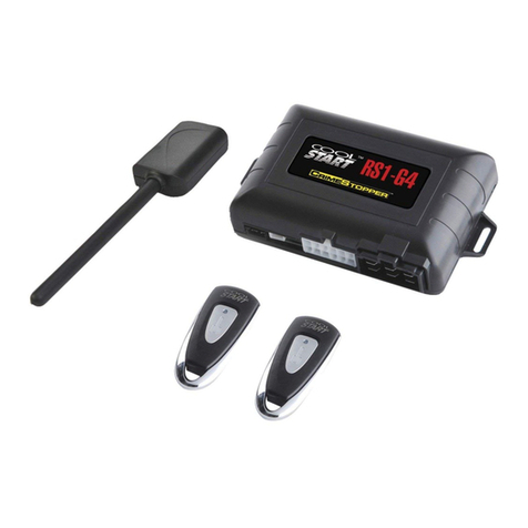
Cool Start DS-1 User manual

DS-1/ DS-3/ DS-4 (1-Way)
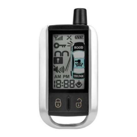
DS-7(2-WayPaging)
DS-00 (ADD-ON MODULE)
DATASTART SYSTEMS
INSTALLATIONINSTRUCTIONS
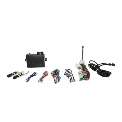
CONGRATULATIONS on your choiceofaDataStart™RemoteEngine Starter and Keyless EntrywithDataPort
TechnologybyCrimestopper SecurityProductsInc. Thissystemisdesigned tobe used inconjunction withaDatabus
Bypass Moduleand WILL NOTworkbyitselfasastand alone remotestarter.Thisbookletcontainsthe information
necessaryfor installing your system.
Note:Some features will notbeavailableon unitswith 1button, 3button, and 4button remotes.
DISCLAIMER:
Thisinstallation bookisdesigned for the installer or individualwithan existing understanding ofautomotiveelectrical
systems,along withthe abilitytotestand connectwiresfor proper operation.Toeaseinstallation,wesuggestthatyou
READ THISMANUAL before beginning your installation.Thisbookisprovided asaGENERALGUIDELINEand the
informationcontainedhereinmaydifferfromyourvehicle.CrimestopperSecurityProducts,Inc.andits’vendorsshallnot
beliableforanyaccidentresultingfromtheuseofthisproduct. Thissystemisdesignedtobeprofessionallyinstalledinto
avehicleinwhichall systemsand associated componentsare inperfect working condition.
TECHNICALSUPPORT:(800) 998-6880
Monday-Friday8:00am-4:30pmPacificStd. Time
Web Site: www.crimestopper.com
E-mail: tech-support@crimestopper.com
CRIMESTOPPERSECURITYPRODUCTS, INC.
1770 S. TAPO STREET, SIMIVALLEY, CA. 93063
REV 08-2012
ThisdevicecomplieswithFCC Rulespart15.Operationissubjectto
the following twocond
itions:(1)Thisdevicemaynotcauseharmful
interference,and (2)Thisdevicemustacceptanyinterferencethat
maybe received,including interferencethatmaycauseundesired
operation. The manufacturerisnot responsibleforanyradioorTV
interfer
encecaused byunauthorized modificationstothisequipment.
Suchmodification couldvoidthe user’sauthoritytousethe
equipment.

2
TABLEOF CONTENTS
Pre-Installation Considerations….………...……...………………………………………………………………..….………..2
Installation Cautions&Warnings………………………………………………………………………………..….....……..…3
5PinPower Plug……..…………………………………………………………………………………………....…………......3
Optional8PinPlug...…………………………………….…………….……..…………...….…………..………….………..4-5
AUXChannelOutput (Trunkrelease, Domelight or Horn honk)…..……………………………………………..…………5
Door Lock Diagrams………….……………………….…………………..…..…….…......………………………………….…6
Smart Tachless Mode…..………….…………………………………………………………………………....….…..............7
TachProgramming Options….…………….……………………………...……………………...…..…………..…….………8
Option Programming Table….………. …….………….……………………………..……………..…….....….….....……..8-9
Option Descriptions……………..……………………………...………….……….……..…………………………...……11-15
Antenna Diagram……………………….…………………………………………………………..………………………..….15
Transmitter Programming and 2VehicleProgramming………………………….….…………….…...…..…..……..........16
ManualTransmission Mode……………………….………………………………...…………………….….……..…………17
SystemWiring Diagram……………….………….………………………………...…………………….….……..……..……18
DataPort………………………………………..………………………………..………..….……….…………………………19
RemoteStart Diagnostics.…………….…………………………………………………………..…………………….…..….20
PRE-INSTALLATIONCONSIDERATIONS
BEFORE BEGINNING,check all vehiclemanufacturer cautionsandwarnings regardingelectricalservice (AIR BAGS, ABS
BRAKES, ENGINE / BODYCOMPUTER AND BATTERY).
PLANOUT YOUR INSTALLATION anddeterminemost suitablelocationsfor all components to be placed. These components
include: themoduleitself, valet/program button,possiblerelays, andantenna/receiver (RS1, RS3andRS4 only,theRS00 model
does not include antennaor remotes.) Allow enoughwire to create aservice loop withstrainrelief, shouldservicingbe required.
This will also allow easier access and mounting.
DAMAGE to the Data Start unit resultingfrom incorrect installation or failure to follow guidelines stated in thisbook will not be
covered under warranty and will be subject to repair or replacement charges.
USE AVOLTOHM METER to test and locate all connections. Test Lights candamage a vehicle’s computer systems.
ADDITIONALPARTS,whichare not included withthisunit, may be needed for yourparticular vehicle. These itemsmay include
extra relays or Anti-Theft System Bypass modules.
3
INSTALLATIONCAUTIONS&WARNINGS
ThisSystemisaLow CurrentRemote Startthat onlyworks inData ModewithaBypass Module.
DONOT routeanywiring thatmaybecomeentangledwithbrake,gaspedals,steeringcolumnoranyothermovingparts
inthe vehicle.
DONOT exceed the rated outputcurrentofanycircuiton the Remotestartmodule.Failure toobservethiswarning will
result indamage tothe unit not covered under warranty.
DONOT remotestartthe vehicleinaclosed garage!Makesure thatthe garage door isopen or there isadequate
ventilation. Failure toobservethisrulecouldresult ininjuryor deathfrompoisonousCarbon Monoxide fumes.
WIRING5Pin PowerPlug
RED:12 VoltPowerSource 10 Amp
Connect toaconstant power sourceat batteryor fuseboxwhen powering the Pinkand Pink/whitewire. The ignition
switchon manynewvehicleshaveonlya2or 3amppower wire sothiscan not be used. Not necessarytoconnect
when using aDataModulewitha“T”harness plug. The dataplug can supply1amptooperatethe electronics.
BLACK:MAINSYSTEMGROUND
Connecttochassismetalofthe vehicle.Anexisting boltor screwmayprovide an adequateground,or drill asmall hole,
scrape awaypaintand attachusing asheetmetalscrew&star washer.Thiswire mustbe connectedtoaproperground
or undesirableand inconsistent operation will occur. Donot useFactoryground locations.
PINK/WHITE:ProgrammableOption #4
Thisisan optionalmulti-function outputwire the can be configured asaSecond IGN,ACC or STARTERoutput. Use
Option #4 toselect ACC, IGNor STARTER. The DEFAULTsetting isIGNITION.
PINK:Ignition Input/Output10 AmpMax
Thisisthe ignition sourcefor programming system. Thisalsosupplies12 voltsout during Ignition and Start for remote
starting vehicle. Somedatamodulessupplythisfunction somaynot be necessarytoconnect. Consult installation
guide of datamodule
WHITE:Parking LightOutput(-) 500 milliamp
Thisisused toactivatemarker lightsduring remotestart and signalremotelockand unlock.

4
OPTIONAL 8Pin Plug
Thisplug isoptionaland maynotbe needed withmanydatabusbypass modules.Checkthe databusguide for latest
manualwithwiring information before using thisplug.Theseare optionalfeaturesthatmaynotbe included withthe
bypass module.
YELLOWBLACK OUTPUT:Ground OutwhenRunning (-) 500 milliamp
The Ground Outwhen Running isrequired bysomebypass modules.Thiswire turnson when the remotestartbutton is
pressed and stayson through the duration of the remotestart.
GREEN:LOCK OUTPUT(-) 500 milliamp(See page6forbasicdoorlock diagrams).
BLUE:UNLOCK OUTPUT(-) 500 milliamp(See page6forbasicdoorlock diagrams).
ORANGE:OEMREARMOUTPUT(-) 500 milliamp
Thiswire providesaground pulsetorearmthevehicles'FACTORYanti-theftsystemafteratimed-outorabortedremote
start. Connect thiswire tothe vehicles' anti-theft rearmwire or tothe door pincircuitdepending on your requirements.
Thiswire maybe needed topulsethe door pincircuit on vehicleswithretained accessorypower.
ORANGEBLACK:OEMDISARMOUTPUT(-) 500 milliamp
Thiswire providesaGround pulsetodisarmthevehicles'Factoryanti-theftsystempriortoaRemoteStart. Connectthis
wire tothe vehicles' anti-theft disarmwire.Thiswire issometimesfound coming offtheDriver'sdoorkeyswitchoratthe
FactoryAnti-theft controlmodule. Thiswire maynot be needed if FactorySecurityonlyrequiresadoor unlockpulse.
GRAY:(-) NEGATIVE HOODSWITCH
Connectthe Graywire toaswitchthatisatground when the hood isopen.Ifan existing switchisnotavailable,then we
recommendonetobeinstalled.Whenthiswireisgrounded,theremotestartisinhibited.Theunitwillnotattempttostart
if hood isopen.
PURPLE:(12V)BRAKERESET
Connectthe Purplewire tothesideofbrakepedalswitchthatshows12voltsONLYwhenpedalisdepressed.Thisisthe
wire that turnsoff the remotestart oncethe driver’skeyisinthe Ignition and turned tothe ONposition.

5
AUXOutput(TrunkRelease –Dome Light–Horn Honk)
BROWN:AUXOUTPUT(-) 500 milliamp
Thisoutput isprogrammablefor 3modesof operation. See Programming Option #9 Section.
1.30 second DomeLight output.
2.Momentary½second output (Default).
3.Horn Honkoutput.
Note:SomevehicleslikeLexusand Toyotarequire a2to3second output for the TrunkPop tooperate. Thisoutput is
selectablefor Momentary½second (default)or aPress and Holdfunction Option 6-3 (outputstayson until Transmitter
button isreleased).
Brown
85 86
30 87
TrunkSolenoid
DomeLight
TRUNK OUTPUTorDOMELIGHTorHORN HONK
OR*
(Default)
+12VCONSTANT
+12VCONSTANT
HornHonk
-or-
*Testactivation circuitinvehicle.
Connectto+12VforPositivecircuits
orGround forNegativecircuits.Relay
notincluded.

6
DOORLOCK DIAGRAMS
AFTERMARKETMOTOR/DOORLOCKWIRING
REVERSE POLARITYDOORLOCKWIRING
GREEN
GREEN FUSED
FUSED RED
RED +12V
+12V BLUE
BLUE +
+
86858685
8685
8685 8787
8787 3087A3087A
3087A3087A
+L
CUT
UL
CUT
MASTER
SWITCH
NEGATIVETRIGGERDOORLOCK WIRING POSITIVE TRIGGERDOORLOCK WIRING
GREEN
GREEN FUSED
RED +12VRED BLUE +
BLUE
86
858685 8787 3087A30
87A
FACTORY
FACTORY
LL
POWER
POWER LOCKING
LOCKING
UL UL
RELAYS RELAYS

7
StatusLEDand ValetSwitch
PROGRAMOVERRIDESWITCH:2PINPLUG (REQUIREDFORPROGRAMMING &LEARNING REMOTES)
Thisisamulti-function switchused for programming options, transmitters, Valet mode.
LED:2PINPLUG
The LEDisused for RemoteStart Diagnostics and aValet indicator. It will alsoflashfor useassecuritydeterrent.
VALET/ PROGRAMSWITCH
STATUS LED
“SMART TACHLESS”MODE
Your DataStartsystemincludesaunique voltage monitor called “SmartTachless”mode.Thismode allowsthisunitto
efficientlystartan engine withoutthe useofatachsignalwire.Thismoduleactivelymonitorsthe voltage levelofthe
vehicletocontrolthe starter motor eachtimearemotestart isrequested.
IMPORTANTNOTES:
(1)Onthe rare occasion that“SmartTachless”mode doesnotoperatesatisfactorily,change the voltage referencelevel
asdescribed below, or useadifferent mode suchas“Tach” mode, or “Timed Crank”mode.
“SMARTTACHLESS”ADJUSTMENT:Option #21
Inthe event“SmartTachless”over-cranksor under-cranksyour starter,the settingscan be changed.The purposeof
adjusting the “SmartTachless”Mode istoraiseor lower the voltage referencethresholdfromthe 93%defaultpoint.
Raisingorloweringthis93%pointshouldincreaseordecreaseyourcrankingtimerespectively.Theadjustmentrangeis
from79%to100%inone percent increments. Thisrequiresa4button remotetochange reference.

8
TACH PROGRAMMING&TACH SIGNALS
INTRODUCTION
Thissystemhas3methodsofmonitoring the engine running.Option #1 controlshowthe systemmonitorsthe engine
running.
1. TachReference Mode–MonitorsEngineR.P.M. -Most reliablemethod, see Tachprogramming below.
2. Tachless Mode-Default. When vehicleisremotestarted, the batteryvoltage ratewill go up becausethe
Alternator startsworking. The Tachless Mode isadjustablein1%incrementsthru Option 21.
3. Not Used.
4. HybridMode– For “PushtoStart”vehiclesor computer controlled starters. Thisprovidesa4second crank
output toactivatethe start sequenceon Hybridor PushtoStart vehicle. ThisisaTimed Start Mode. DoNot use
on vehiclesthat can over crankthe starter unless you adjust the Starter CrankTime(see option 18).
TACH PROGRAMMING: Datamodulemust supplyTachsourcetoprogramthisoption.
1.Start engine withkey.
2.Press programbutton 5times, then wait for 5light flashesor parklight LEDflashes5times.
3.Pushprogrambutton oncemore. (You must get one light flashafter button ispressed.)Thisunit isnowat option
#1-TachLearning.
4.Press the #1 LockButton on remotetransmitter or step on brake. The unit will read the Tachsourceand flashthe
lightsoncefor programconfirmation. If lightsdo not flashfor confirmation, then the datamoduledoesn’t supplya
Tachsource.
OPTIONPROGRAMMING
ThisDataStartunithasover26programmablecontroloptionstocustomizethesystemforvariousoperatingfeaturesand
installer preferences.Examine the charton the pages9-10 along withreading the descriptionsthatfollowon pages11-
15.You maychange one option atatime,or programmultipleoptionsinone session.Ifyou startwiththe lowestoption
and continue on tohigher options,you donotneedtorepeatsteps#1-3eachtime.Forexample,youcanchangeOption
#2 to“ON”, then you can continue pressing the programbutton toget toahigher number option and change itaswell.
You can onlygo fromlowtohigher optionsnumbersinone session.

9
OPTIONPROGRAMMING
To EngageOption Programming:
1. Turn Ignition Keytothe ONposition. Donot start vehicle.
2.Press the Program/ Valet button 5times. Wait for the unit toflashthe lightsor parklight LEDflashes5times.
3.Pushthe valet programbutton the number of timesthat correspondstothe option number desired (1-26X). You
must get alight flashafter eachbutton press. If the systemdidnot flashthe lightsand, then it didnot register your
press. Press carefullyand do not losecount.
4. ForDS-3, DS-4, DS-7: When you reachthe desired option #, tochange the option: Press button #1 Lock,#2
Unlock, #3 Trunk, #4 Start. (Someoption numbersuseALL 4remotebuttonstoselect settings)
5. ForDS-00, DS-1: (NoLockbutton) tap the brakepedaltotogglethrough the option values: Tap brakeonce
(lightsflash1X)Tap the brakepedalagain(Lightsflash2X)tap 3or 4timesfor optionsthat have3or 4values.
6.When finished, turn Ignition OFF, and checkfor changed features.
OPTIONPROGRAMMINGTABLE
Option #
Option Description TXButton #1 TXButton #2
DefaultValue TXButton #3 TXButton #4
1 EngineMonitoring Tach (thru data) *Tachless* Hybrid
2 Autolock withRPM/ Ignition ON *OFF*
3 DoorLock Pulse 3 Seconds *0.50 Seconds* DoubleUnlock “Wake Up”pulse
withUnlock
4 Pink/whiteWireSelection ACC *IGN* START
5 DataPortProtocol ADSiDatalink-
OFASeries *Fortin-
EVO / SLSeries*
6 RemoteStart&TrunkRelease
ButtonSelection DoubleButtonPress *½Second Press* Press andHold
7 HornChirpsonRemoteStart ON *OFF*

10
Option #
Option Description TXButton #1 TXButton #2
DefaultValue
TXButton #3 TXButton #4
8 Lock withRemoteStart/ Abort OFF *Lock after
RemoteStart*
Lock afterRemote
Start/ Arm OEM
Alarm withAbort
Lock / Arm OEM
Alarm withAbort
9 Brownwirefunction DomeLight *Trunkpop* HornHonk
10 Unlock beforeRemoteStart
(toDisarm OEMAlarm) ON *OFF*
11 TransmissionType (thru data) Manual Transmission
withRemoteControl *OFF* Manual Transmission
setwithHandBrake
12 IdleDownTimer 10 Minutes *20 Minutes* 30 Minutes InfinityRun
13 HornChirpConfirmation 1Press *2Press*
14 Unlock withTrunkPop Unlock/TrunkPop *TrunkPop only*
15 30 Sec. ParkLightswithUnlock
OFF *ON*
16 HornPulse (Chirp) 15 milliseconds *20 milliseconds*
40 milliseconds
17 OEMInterface (thru data) 3press Lock =Remote
StartwithOEMremote *OFF*
18 MinimumStarterCrankingTime
(-) 0.1Seconds *0.8Seconds* (+)0.1Seconds (+)0.4Seconds
19 Diesel Glow PlugDelay 10 Seconds *4Seconds* 15 Seconds 20 Seconds
20 RemoteStartEngineRun Time 10 Minutes *20 Minutes* 30 Minutes 5 Minutes
21 SmartTachless Voltage
Adjustment79-100%-1% *Set to93%
default* +1%
22 Turbo TimerMode 1 Minute *OFF* 3Minutes 5 Minutes
23
Unlock onStartButton
afterRemoteStart Momentarypress =Unlock
2Sec. press =Start/ Abort *OFF*
24 NOTUSED
25 1-Wayor2-WaySystem 2-Way 1-Way
26 ResetOptionstoDefault(*) Reset Options1thru23 (2Flashes)

11
OPTIONDESCRIPTIONS
1. EngineMonitoring:
Thisoption controlshowthe systemmonitorsthe engine running.You can programfor Tachless mode thatmonitors
batteryvoltage,Tachmode inwhichthe unitusesaTachsignal(RPM)orforTimedCrankasanalternative.Thereare4
choicesfor thisoption:
1.Engine R.P.M. (Tach) -Most reliablemethod. Tachmust be programmed for thisoption towork.
2. Tachless Mode-Default. When vehicleisremotestarted, the batteryvoltage ratewill go up becausethe
Alternator startsworking. The Tachless Mode isadjustablein1%incrementsthru Option 21.
3.Blank–NoFunction
4.HybridMode –For electricmotorsthat are computer controlled. Thisprovidesa4.0second crankoutput to
activatethe start sequenceon Hybridvehicle. Don’t useon vehicleswithgasor dieselengine, doesn’t monitor
engine running or lowbatteryvoltage. Option #18 allowsyou toshorten starter cranktimeif necessary.
2. AUTO LOCK and UNLOCK withIGNITION:
Thisfeaturecontrolswhetherthedoorswillautomaticallylockwhentheignitionisturnedonandunlockwhentheignition
isturnedoff.IfthesystemisinTachmode,thenthedoorswilllockastheengineRPM’sincrease(driving).Somevehicles
alreadyhavethisfeature fromthe factoryyou shouldturn off thisoption. Doorswill not lock if theyare open toprevent
locking the keys in. There are 2choices:
1. OFF =NoLockor Unlockwithignition.
2. Ignition ON=Lock, Ignition OFF =Unlock -Default.
3. DOORLOCKS:
Thisoption setshowthe door lockcircuit works. There are 4choices:
1.3Second Lockand Unlock-For older European vehiclesthatrequire along lockand unlockpulsetooperate
Vacuumdoor locksystems.
2. 0.8Second Lock and Unlock -Default.
3.DoubleUnlock–Thisfeature maybe required tointerfacewithafactoryalarmor keyless entrysystem. The first
pulsedisarmsthe factoryalarm; the 2nd pulseunlocksthe doors.
4.“WakeUp” pulseon Unlock-0.8second unlockpulsealong withIgnition,Disarmand (-) RUN towakeupaBCM.
Thisfeature maybe required tointerfacewithafactoryalarmor keyless entrysystem.

12
OPTIONDESCRIPTIONS
4.PINK / WHITEWIRESELECTION:
Thisoption controlsthe Pink/ Whitewire function.
1.Pink/ White=Accessory2
2.Pink/ White =Ignition 2-Default.
3.Pink/ White=Start 2
5. DATAPORTPROTOCOL: ADSiDatalinkorEVO / SLSeries
ThisoptioncontrolstheDataPortProtocolforADS/OFASeriesmodulesorEVO/SLSeriesmodules.Thedefaultisset
for EVO/SLSeriesProtocol.Thisoption hasno effecton conventionalwiring ofBypass modules.BothDataProtocols
are 2-Waycommunication.
6. REMOTESTART&AUXOUTPUT:Button Press Selection:
Toeliminatethe possibilityofaccidentallyopening the trunkor starting the vehicle,there are (3) optionsfor button press
selection. Thisoption will allowyou tochange whether the Remotestarter and Trunkreleaseactivatebya:
1.Doublebutton -½second presses.
2. Single½second press -Default.
3.Press and Hold2seconds. Note: AUXoutput will stayon until TXbutton isreleased
7. HORN CHIRPS withREMOTESTARTACTIVATION:
Thisoption allowsthe unittoprovide 3shortchirpsfor audibleconfirmation ofaremotestart. The horn outputwire must
be connected for thisfeature. Default=OFF.
8. LOCK withREMOTESTART:
Thisoption controlswhether the unitwill automaticallylockduring and after aremoteStartabortortime-out.Thereare4
choicesfor thisoption:
1.OFF
2.Lock withRemote StartOnly-Default.
3.LockwithRemoteStart and Lock/ ArmwithRemoteStart Abort -Default.
4.Lock/ ArmwithRemoteStart Abort only
9. BROWNWIREFUNCTION:AUX1-TrunkRelease, DomeLightorHornHonkOutput:
Thisoption controlshowthe Brownoutput wire of the unit functions. There are 3choicesfor thisoption. Thisoutput
can be programmed for 30 second DomeLight withunlock, TrunkReleaseor Horn Honk.
Default=TrunkRelease

13
OPTIONDESCRIPTIONS
10. UNLOCK BEFOREREMOTESTART:
Thisoption isused todisarman OEMAlarmSystembefore RemoteStart. Default=OFF
11. TRANSMISSIONTYPE:Requires TachModeProgrammed
Thisoption selectsautomaticor manualtransmission mode inDataMode only
1. ManualShift Transmission -RequiresRemoteStart Button pressed withHand BrakeActivated.
2.AutomaticTransmission –Default.
3. ManualShift Transmission –StartsExit procedure withHand BrakeSet and engine running.
12. IDLEDOWNRUN TIME:
Thisfeature allowsthe remotestarter totakeover operation of aparked vehiclewhen the ignition keyisremoved and
you exit the vehicle. The vehiclewill remainrunning for the programmed timeor until canceled. The choicesare: 10,
20, 30 minutesor InfinityRun. Default=20 minutes.
13. HORN CHIRPwithLOCK and UNLOCK -1or2Button Press
Thisoptionallows thesystem to chirp thevehiclehornfor Lock/Unlock confirmationon1buttonpress or a2nd press within3
seconds. The hornoutput must be connected to use this feature. Default =2 Press.
14. UNLOCK WithTRUNK POP:
Thisoptioncontrolswhether thesystem will provide anUnlock /Disarm pulse whentheTrunkreleaseisactivated fromtheremote
control. This may be required to prevent unnecessary triggering of a factory alarm onsome vehicles. Default =OFF.
15. PARK LIGHTSON30 SECONDSwithUNLOCK:
Keepsparking lightson withremoteunlocktoassistinlocating and providing illumination near your vehiclewhen
approaching at night for safety. The parking light alsoturnsoff withignition on. Default=ON.
16. HORN PULSE DURATION:
Thisoption allowsadjustment the “CHIRP”pulseduration of the car horns. The choicesare 15, 20 or 40 milliseconds.
17. OEMInterface (DS-00 Add on Model): 3Pulse Lock =StartthruData
Thismode allowsthe systemtousethe OEMRemoteControltoRemoteStart or Stop with3successiveLockpulses.
Thisfeature onlyworkson newer CANBUSvehicleusing aDataModulethatsupportsthisfeature.Withthisoption you
can useboththe OEMand Crimestopper remote. Mayrequire customprogramming of Datamodule.

14
OPTIONDESCRIPTIONS
18. MINIMUN STARTERCRANK TIME: Default=0.8seconds
Thisoption controlsthe MinimumStarter Cranking time.Thisdoesnotaffectmaximumcranktime.Thiscanbeadjusted
in0.1secondincrementsUporDownfrom0.5to4seconds.Thestartercanstillcrankupto4secondswitha0.8setting,
depending on Tachor Tachless setting.
TIMEDSTART,useHybridMode(option1-4)withthisoptiontosetafixedcranktime.PleaseNote:InHybridMode
there isonly1start attempt and the ignition isleft on.
19. DIESELGLOWPLUG DELAY:
Thisoption controlsthe system’sDieselvehicleinterface.Using thisoption you can selectaspecificdelaytimebefore
cranking. Selections: 4, 10, 15 or 20 seconds. Default=4Seconds
20. REMOTESTARTENGINERUN TIME: Set engine run timefor 10, 20, 30 or 3minutesasdesired.
21. SMARTTACHLESS VOLTAGEADJUSTMENT:
ThisoptioncontrolsthevoltagereferencepointwhenusingsmartTachlessmode.PressingtheLockorTrunkbuttonson
the remoteraisesor lowersthe referencelevelin1%incrementsfrom79%-100%.Button #2 (unlock)resetsthe unitto
the factorydefault referencepoint of 93%. The default 93%setting worksfor most vehicles.
22. TURBO TIMER:Using Remote StartButton
The optionalTurbo Timer mode allowsthe DataStart systemtokeep aTurbo or Turbo Dieselvehiclerunning for 1, 3
or 5minutes[selectively] after you removethe keyand exit the vehicle. Thisishandyfor turbo cool-downwithout the
need for expensiveturbo timers. The Default=OFF.
23. UNLOCK ONSTARTBUTTON:
Whileremotestarted, thisoption allowsthe remotestart button tounlockthe doorswitha½second press.
24. NOTUSED
25. 1-WAYor2-WAYSYSTEM:
Thisselects1-Wayor 2-Wayantenna system. The 1-WaysystemusesAMtransmission. The 2-Waysystemuses
FMtransmission. The RFrange will be muchimproved using the FM2-Wayantenna system. You must select this
option using the brakepedalor remotecontrol. If you accidentallychange systemfrom1-Wayto2-Way(or vise
versa), you need tousethe brakepedaltochange option 25 backtocorrect antenna system.

15
OPTIONDESCRIPTIONS
26. OPTIONRESET:(RESTORETO DEFAULT)
Thisoption restoresall programmableoptions1thru 23 tofactorydefault. The unitwill flashthe lights2timesand all
valueswill be resettofactoryoriginalsettings. Resetting theoption tabletodefaultdoes notchangethetypeof
antennasystem.
ANTENNADIAGRAM
Antenna shouldbe located at top of widowat least one inchawayfrommetalsurface.
WINDSHIELD
ANTENNA
LOCATIONS

16
TRANSMITTERPROGRAMMING
TransmitterProgramming:
Notes:RemoteTransmitters/Transceiverscomepre-programmedfromtheFactory.Whenre-learningremotesoradding
remotes,ALL your system’sremotecodesmustbe learned attimeofprogramming!! Thesesystemsallowstorage ofup
to4different remotecodesinmemory.
1. Turn Ignition Keytothe ONposition. (Donot start vehicle).
2.Press Program/Valet button 4times. Wait for the unittoflashthe parking lightsand parklightLEDflashesexactly4
times.
3.Press button #1 ofthe firsttransmitter.You shouldget1lightflashconfirming the remoteiscoded,then press button
#1 ofasecond transmitter,the unitwill flash2timesconfirming the remoteiscoded and soon.Ifall 4codesare
learned, the unit will automaticallyexit code learning mode, otherwiseturn keyoff. See diagrambelow.
IGN
OFF
WAITFOR
4FLASHES
PRESS4X's
FLASH2,3,or4X's
DS1Only
IGN
OFF
LOCK
PRESS
STARTONLY
DS3thruDS7
COMPLETE
PRESS
2VEHICLEOPERATIONand PROGRAMMING: Toset up the 2vehicleoperation you must haveall 4remotesfor
programming. For the first vehicle(remotes1&2) press the Lockasinstep 1thru 3. Tochange fromvehicle1to
vehicle2, press the VEH button on remotefor about 2seconds. The LEDon remotewill change fromblue tored.

17
MANUAL TRANSMISSIONMODE
MANUALTRANSMISSIONINSTALLATION:
Thisoption requires adatabusmodulewithhand brake and doorstatusfeature. TheDoorand Hand Brake
StatusonlyworkthruData Mode.
OPTION11 -TRANSMISSIONTYPE:Manual Transmission Requires Tachprogrammedtooperate.
Thisoption selectsautomaticor manualtransmission mode -3Choicesof operation.
1. ManualShift Transmission -RequiresRemoteStart Button pressed with(-) Hand Brakeset.
2.AutomaticTransmission –Default.
3. ManualShift Transmission –StartsExitprocedure with(-) Hand BrakeSetand engine running.Notnecessaryto
press remotestart button.
Manual Transmission ExitProcedure:
1. Option 11-1: Withenginerunningandvehicleinneutral,setparkingbrake,thenpress“Start”buttonontransmitter.
The remotestarter will turn on and takeover operation of the vehicle.
2. Option 11-3: Withenginerunningandvehicleinneutral,setparkingbrake.Theremotestarterwillturnonandtake
over operation of the vehicle.
3. Removekey, exit vehicle(remotestarter unit must “SEE”door opened, then closed withengine running).
4. PressLockbuttonwithin10secondsofclosingdoorfor“IdleDown”(enginestaysrunning).PressLocka2nd timeto
cancel“IdleDown” (engine turnsoff)and set up ManualTransmission Mode.
5. Press Lockbutton after 10 secondstoLockthe doorsand shutdownthe engine.Fromthispoint, the systemwill
remotestart the engine unless adoor isopened.
6. Press the RemoteStartButton after closing door tosetup ManualTransmission Mode withoutLocking or Arming
OEMAlarmSystem.

18
OVERRIDE/
PROGRAM
BUTTON
DATAPORTS
STATUSLED
ANTENNA
ParkLight
LED
ADSiDataLink
Fortin
Hood Switch
(-) Gray
(+)BrakeSwitch Purple
Ground when
RUNNING
(Bypass Module)
OPTION#9
TrunkRelease, DomeLightorHornHonk
10Amp
FUSE
(-) Parking Lights
OPTION#4Selectable
IGNITION
SWITCH
Pink/white
Pink
White
Red
Black
Ground
IGNITION
IGN/ ACC / START
12VoltsPowerSource
(-) OEMDisarm
(-) Unlock
(-) OEMArm Yellow/black
Brown
Blue
Orange
Orange/Black
DATASTART
WiringDiagram
(-) Lock Green
(-) AuxOutput
1-Way or2-Way
Option#25
Thisunitisdesignedtoworkin
conjunction withaDatabusModule
(-) 500mA
(-) 500mA
(-) 500mA
(-) 500mA
(-) 500mA
Optional
(-) 500mA

19
DATAPORT
This unit requires a Databus Module for Remote Start. There are 2typesof Protocol, ADSiDatalinkand EVO SLseries
modules. The default isset for EVO SLseriesProtocol. Pleaserefer toDatabusmodulemanualfor detail
instructions. The DataPort Protocolmust be programmed for the correct module.
See Option #5on page9forprogramming Data Port
ManylatemodelGMand Chrysler vehiclesmayhaveaDatabusModulewithT-Harness availablefor minimalwiring
toBypass the factoryImmobilizer and operatethe keyless entry.
Checkthe Databusfit guide at www.crimestopper.com
Besure todownload the latest install manualfromthe Databusmodulefit guide and load the latest firmware
available.
Features Include
•Transponder Immobilizer.
•PassLockImmobilizer.
•O.E.M. AlarmControl.
•R.A.P. Shutdown.
•Power Door Locks.
•PriorityUnlock.
•TrunkRelease.
•Parking Lights.
•CourtesyLights.
•BrakePedaland Hand Brake
•Hood, Door and TrunkStatus
•Tachometer.
•Heated Seats.
•Rear Defrost.
•Driver 1and 2Memorypresets.
The actualfeaturescontrolled depend on the vehicleand Databusmodule.

20
REMOTESTART DIAGNOSTICS
Ifthesystemflashes theLEDand Parking Lightsonetoseventimes and doesn’tattemptremote.TheLEDwill continueto
flashing theerrorcodeuntil theignition isturnedon, itmeansthefollowing:
1ParkingLightFlash(1LEDFlash)=ProblemwithBrake Switch.
2ParkingLightFlashes (2LEDFlashes)=ProblemwithHood Switch.
3ParkingLightFlashes (SolidLED)=ValetService Mode.
5ParkingLightFlashes (5LEDFlashes)=IgnitionOnbeforeRemoteStartorTachproblem.
6ParkingLightFlashes (6LEDFlashes)=TachProblem(Tachsignal withoutenginerunning)
7ParkingLightFlashes (7LEDFlashes)=Manual TransmissionError.
Note:InManual TransmissionMode, theLEDwill Flash3times iftheparkingparkisnotset.
www.crimestopper.com
Phone (800)998-6880
FAX (805)581-9500
©2012 CrimestopperSecurityProducts
ONLINETECHNICALSUPPORT
www.crimestopper.com
Phone (800)998-6880
FAX (805)581-9500
©2012CrimestopperSecurityProducts
This manual suits for next models
4
Table of contents
Other Cool Start Remote Starter manuals