Criminalistics Premier Canine System Plus User manual

Criminalistics, Inc. 7560 NW 82nd St., Miami, FL 33166, (305) 885 6444, Fax (305) 885 3330
1391 Main Ave., Morton, WA 98356, (360) 496 6363, Fax (360) 496 6210
- 1 -
Premier Canine System™Plus
Remote Door Opening and Temperature Monitoring/Alerting System for Canine Vehicles
Congratulations! You have purchased the most advanced door opening and temperature monitoring system available
today. Your Premier Canine SystemTM Plus incorporates the acclaimed one-button door release features of the
distinguished Bail OutTM system and the proven reliability of the HotdogTM temperature monitoring system.
Criminalistics, Inc.
is committed to providing the best in reliability, quality and support at an affordable value.
K-9 Officers & Installers: PLEASE take time to read the instructions carefully. This is a life saving system, proper
installation and operating procedures must be taken seriously.
Familiarize yourself with all system functions and operational modes. TEST YOUR SYSTEM DAILY!
Overview/Operational Summary
Your Premier Canine SystemTM Plus door opening system is supplied with 40-pounds of pneumatic push power (a gas spring).
This unique systemwill unlock, unlatch and push open your vehicle door with the press of a single button from up to 500 feet
away. The door unlatch solenoid is rated for 15 pounds. Most door latches typically require a 5-pound pull. This unit has the
strength to operate the door of most standard patrol vehicles. Your Premier Canine SystemTM Plus is individually coded for a
specific vehicle to ensure that the door with the corresponding code will open. A necessary advantage when multiple systems are
used within an agency.
As an added safety feature, there is a Door Opener interlock, where the vehicle must be in Park, Neutral or a VSS (Vehicle Speed
Sensor) sensor connection, which will disable the door opening function when the vehicle is moving.
If your programmed maximum temperature is exceeded and/or the back up sensor maximum temperature is exceeded (92oF -
94oF) your Premier Canine SystemTM Plus will lower two electric windows, activate the Accessory output (typically a horn or
lights), summon you via a
optional
pager, from up to 1 mile away, and turn on the high volume fan. Your system will cycle/alert
continuously until the interior temperature decreases below the programmed maximum temperature or below the back up sensor
reset temperature of (91o) unless the unit is turned off by the user, or if the vehicle battery dies.
The optional pager can also function as a vehicle burglar alarm with the addition of
options
that include glass breakage detectors,
motion sensors, key lock alarms and starter kill functions. Please feel free to contact Criminalistics, Inc. for additional information
regarding these products.

Criminalistics, Inc. 7560 NW 82nd St., Miami, FL 33166, (305) 885 6444, Fax (305) 885 3330
1391 Main Ave., Morton, WA 98356, (360) 496 6363, Fax (360) 496 6210
- 2 -
Operation and Programming:
To turn the unit on, lift the “Lock/On” switch lever up (
this is a locking switch and the lever has a slide collar, lift the
collar to change it’s position
). The LED should illuminate steady “green”. Place the switch lever to the center position to
turn the unit off. With the “Lock/On” switch in the down position only the
optional pager
system is turned on (for optional
vehicle alarm motion sensors, if installed).
Placing the switch lever in the down position will turn on the “optional” pager system ONLY. The Premier Canine System will NOT be powered on. (Only with the
switch lever down). With the switch lever up both the Premier Canine System and the “optional” pager system (if installed) will be powered on.
To set “High” temperature alarm point:
A) With the system (Lock/On) switch set to the middle (off) position (LED off)
B) Select “high” temperature set. (switch is momentary, press and release) The temperature will blink the last programmed
high alarm temperature.
C) Using the up/down switch select the new desired “high” temperature alarm point. The up/down switch will increase or
decrease in one degree steps or if the switch is held over the temperature will scroll up or down until released. Once the
desired “high” temperature is reached, press the “high” temperature set switch one more time. High temperature alarm
point is now set. (Blinking will stop).
Note: You can confirm the setting with the Lock/On switch centered. Press the “high” temperature set switch once, it will display the current setting,
press the “high” temperature set switch one more time to return to ambient temperature. When a MAX or MIN temperature is recorded, and the
“Lock/On” switch is centered, MAX and/or MIN will be displayed on the LCD.
D) If desired, program the Low temperature, using step B & C above, using “Low” temperature.
Turning Unit On:
Lift the “Lock/On” switch up. The LED should illuminate steady “green” and MEM will appear on the Temperature LCD. If the
temperature reaches the High set point, MAX will appear on the LCD just below MEM. If Low temperature point is set and the
temperature drops below the set point, MIN will appear below MAX on the LCD. The LED will blink and MEM, MAX, or MIN will
blink.
If the LED blinks there is an alarm condition present. (Refer to alarm LED condition codes on the next page)
With the “Lock/On” switch up, pressing the High (or Low) temperature set switch once will display the Highest (or Lowest)
recorded temperature. Pressing the High (or Low) switch one more time will return to ambient temperature. The Temperature
unit has a NiMh rechargeable battery to retain settings for approximately 6 months of nonuse. With normal use the Premier Plus
unit will recharge the battery automatically.
Alarm LED condition codes:
Steady Green: All’s well, system on and active.
Blinking Green: ALARM, Temperature, either primary or backup sensor.
(The Primary sensor will also blink the MAX or MIN on the LCD)
Alternating Red/Orange: ALARM, Low Voltage, and possible Temperature sensor.

Criminalistics, Inc. 7560 NW 82nd St., Miami, FL 33166, (305) 885 6444, Fax (305) 885 3330
1391 Main Ave., Morton, WA 98356, (360) 496 6363, Fax (360) 496 6210
- 3 -
Switch Descriptions:
Backlighting: This switch is used to turn on and off the Temperature LCD back lighting. Up is constant On, Center is Off, and
Down is Momentary On.
Lock/On: Used to turn on the Premier Canine System and for programming the temperature alarm points.
Manual Fan Speed: This switch turns on the fan, either High (full) speed or a lower (medium) speed. This switch will NOT
override the Alarm function. In an Alarm condition the fan will run at high (full) speed until the temperature drops below the high
temperature alarm point.
Temperature Set, High/Low: Selects either the High or Low temperature alarm set point.
Up/Down: Changes the display alarm temperature set either up or down. Momentary pushing the toggle changes the set
temperature in single degree steps. Holding the toggle will scroll the temperature in the direction held. The temperature scroll
will also “wrap around” and start from the most minimum limit.
Temperature Alarm Sequence of Events: When a Temperature Alarm situation occurs 3 things happen simultaneously:
Audio/Visual indicators are activated (typically Horn Honk, Light bar, or Brake lights). Window A rolls down for 5 seconds and the
Fan comes on at high speed. After Window A rolls down Window B will roll down for 5 seconds (if connected).
Bailout (door opener) Function:
This function is activated when the button is pressed on the remote transmitter.
If the vehicle is using any of the vehicle motion sensors the door unlatch function will not function until the sensor is in an
“armed” condition. Sensor can be VSS (Vehicle Speed Sensor), Park + (a 5vdc signal when the vehicle is in Park or Neutral), or
Park – (a ground, when the vehicle is in Park or Neutral).
Sequence of events on a Door Opener button press: Door unlocks, then unlatches. The gas spring pushes the door open allowing
the K-9 partner to exit the vehicle.
Note: The Green front panel LED must be on steady for the Premier Canine SystemTM Alarm function to operate
properly.
WARNING: If jump starting the vehicle the Premier Canine SystemTM is installed in or using the vehicle to jump
start another vehicle, turn off the Premier Canine SystemTM. Failure to do so could possibly damage your Premier
Canine SystemTM and is not covered by warranty.
Criminalistics, Inc. 7560 NW 82nd St., Miami, FL 33166, (305) 885 6444, Fax (305) 885 3330
1391 Main Ave., Morton, WA 98356, (360) 496 6363, Fax (360) 496 6210
- 4 -
Installation
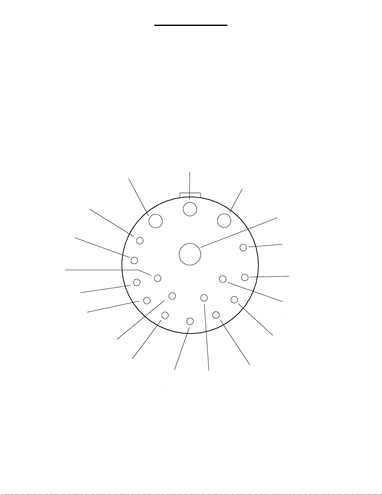
Below is the pin out of the rear panel connector.
1
678
10
9
2
3
4
5
11
12
13
14
15
16
17
18
To Fan
(control/low)
{J13} Main Ground
(Battery Ground)
{J14}
From Door Lock Switch
(Door Lock In)
{J9}
12v Battery
(12v/HV)
{J1}
To Door Lock
(Door Lock Out)
{J8}
From Window B Sw.
(Window B In)
{J5}
Pager Trigger
(TBD)
{J2/J3}
Accessory Out
(Pulse 12v)
{J6}
To Window B
(Window B out)
{J4}
VSS / Park
(BO Inhibit)
{J24}
Engard'e
(Optional Sensor)
{J17}
From WindowA
(WindowAIn)
{J11}
To Window A
(WindowAOut)
{J10}
Backup Sensor Sense
(BU Sensor In)
{J16}
Fan Power
(Fan 12v)
{J1*}
Backup Sensor +5v
(BU Sense 5v)
{J38}
Backup Sensor Ground
(BU Sense Gnd)
{J37}
To Latch / 12v
(Latch out)
{J12}
Base Description
(Schematic Description)
{PCB "J" Connection}
(Looking at connector fromthe outside of the box)
Premier Plus Deutsch Connector Pinout
Criminalistics, Inc. 7560 NW 82nd St., Miami, FL 33166, (305) 885 6444, Fax (305) 885 3330
1391 Main Ave., Morton, WA 98356, (360) 496 6363, Fax (360) 496 6210
- 5 -
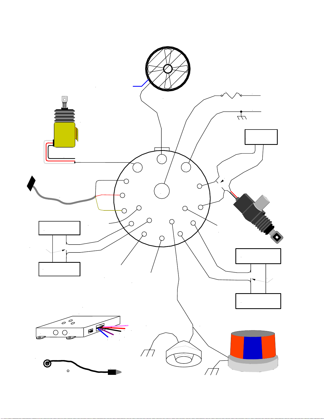
Connection Layout
1
678
10
9
2
3
4
5
11
12
13
14
15
16
17
18
Horn OR Light
Fan
<Fan Power Pin 5 (12v)>
Window Motor B
Window Switch B
Cut original wire
Window Motor A
Window Switch A
<Battery +(12v)>
<Battery ground>
<30A>
Temperature Probe
External Primary
Temperature Probe
Backup
Thermal
Sensor
Antenna Radio
PAGER
- Trigger
+ Trigger
Ground
+12v
Antenna Power
(optional)
<E>
<N>
<n/c>
<n/c>
Door Lock Sw.
cut
original
wire
Cut original wire
Optional Pager
Trigger
VSS / Park + / Park -
Door Opener inhibit
Engard'e
Optional CO2
Sensor Input
Fan Power
Good Door Ground
Door Latch
Solenoid

Criminalistics, Inc. 7560 NW 82nd St., Miami, FL 33166, (305) 885 6444, Fax (305) 885 3330
1391 Main Ave., Morton, WA 98356, (360) 496 6363, Fax (360) 496 6210
- 6 -
Connection List
Pin # Description
1Primary DC In from Vehicle Battery
2Optional Pager Trigger
3Pulse Output, to Horn or Lights
4Window A, in from switch
5Fan Power
6Output to Latch Solenoid
7Output (ground) to Fan
8Ground, Battery, Chassis
9From Door Lock Switch (Door for Dog Exit)
10 To Door Lock Motor
11 From Window B Switch
12 To Window B Motor
13 Door opener inhibit (VSS / Park + / Park –) Input
14 Optional Engard’e input
15 Window A, Out to Motor
16 Backup Sensor (Sense) in
17 Backup Sensor +5v
18 Backup Sensor Ground
List of Package Contents
Each Premier Canine System™ Plus includes the following hardware:
- Premier Control Unit
- Gas Spring (DO NOT expand until installing)
- Hand-held Remote
- Antenna Kit
- 6ft Probe Cable (Black) (3.5mm jack Primary probe)
- 10” Maxi Thin Fan (15” fan optional)
- Fan twin lead 12awg power/control wire with reset able 15A fuse
- Wire Harness composed of:
- Power Wire (+ Battery, 10awg) w/in-line fuse link & 40A Fuse - Ground Wire Black 14 ga.
- 2 Window wires Clear & Blue zip wire 16 ga. - Accessory Wire Red 16 ga. - Unlatch Solenoid Red 12 ga.
- VSS wire Green 16 ga. - Door Unlock Wire (Red/Black zip wire 16 ga.)
- 8ft Backup Probe (Grey), with 1 foot plug in backup sensor on the end (custom lengths available).
- Mounting Screws for Control Unit
- Spare 40 Amp Fuse
Installation Guideline

Criminalistics, Inc. 7560 NW 82nd St., Miami, FL 33166, (305) 885 6444, Fax (305) 885 3330
1391 Main Ave., Morton, WA 98356, (360) 496 6363, Fax (360) 496 6210
- 7 -
Please follow all instructions carefully.Your Premier Canine SystemTM Plus is warranted against defective
components and faulty workmanship for 1 year. Do not hesitate to call if you have any questions. Our engineers and installers
are ready to assist you. You will need a DVM (Digital Volt Meter) for this installation. The 40 amp fuse is required.
INSTALLATION BY QUALIFIED ELECTRONIC TECHNICIAN IS HIGHLY RECOMMENDED
.
Premier Canine System™ Plus Control Unit
Your Premier Canine System™ Plus control unit is housed in a black and silver case with 5 switches and a LCD on the front panel.
Find a functional place to mount your Premier Canine System™ Plus control unit. Most control units are mounted on top of the K-
9 cage (centered) or on top of cage (on the passenger’s side) angled toward driver. When determining the mounting position of
the control unit, consider the following:
•Accessibility of your Premier Canine System™ Plus On/off switch for the operator.
• An area of the vehicle that is dry at all times.
• Keep your Premier Canine SystemTM Plus unit away from any heat source; i.e. heater vents, transmission, floor, sunlight!
The Back Up Heat Sensor must be handled with care. Do not crush, crimp, or twist the Backup Sensor Black end piece.
• Do not install your Premier Canine SystemTM Plus control unit under the vehicle engine hood or in direct sunlight.
• Do not install your Premier Canine SystemTM Plus control unit near any radio equipment.
• Choose placement of your Premier Canine SystemTM Plus control unit near the selected door for ease of installation.
• Place Temperature Probe wire near canine compartment but out of canine’s reach.
Door Unlatch Solenoid:
Select the door to open (traffic or curb side) and remove door panel, and any other obstacles, that block your access to the door's
internal unlatch mechanism. Examine (with the door open) and operate the door with the outside door handle as if you were
opening it, reach inside the door cavity up to the 3/16" rod that is being pushed down by the outside door handle operation.
Observe/feel the downward action of the rod that is connected to the outside door handle. Working from the inside of the door,
use your fingers and pull down on this rod to manually unlatch the door several times. (Engage the latch using a screw driver to
simulate the door being closed and latched around the post. Remove the screw driver before trying to unlatch.)
Near the end of this rod is a factory connector; place the supplied clip lock hook, located at the end of the solenoid pull cable,
over the end of the (external door handle) 3/16" rod directly at the connection point at the latch mechanism (piggy back solenoid
cable clip lock hook on existing rod).
DO NOT mistakenly attach this solenoid to the inner door handle rod for it will
not operate properly.
Some doors may require you to use an inspection mirror to see this rod and a pair of long needle nose pliers to apply the clip.
Note: A door latch lever typically travels a total of 5/8" beginning with 1/4" free movement and then as it moves to 3/8", it
unlatches the door completely. The lever requires a minimum of 4 pounds pull and a positive travel of 3/8" to unlatch, which fits
well within the solenoid travel of 1" and its pulling power of 15 pounds. The solenoid power is supplied by the vehicle battery and
should be maintained by leaving the vehicle engine running during testing of door opening operations to prevent excess battery
drain.
Criminalistics, Inc. 7560 NW 82nd St., Miami, FL 33166, (305) 885 6444, Fax (305) 885 3330
1391 Main Ave., Morton, WA 98356, (360) 496 6363, Fax (360) 496 6210
- 8 -
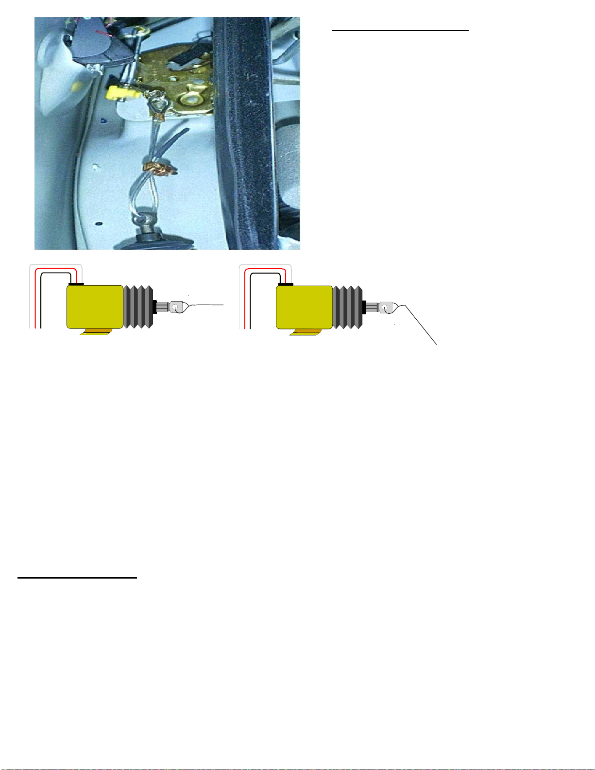
Mounting the Solenoid:
Let the solenoid hang free from the door latch rod and
use it as a positioning guide for mounting. In the
standard Ford Crown Victoria the solenoid mounts below
the latch. With the door open looking at the latch end,
under the latch, measure from the base of the latch
opening down approximately 12" and move as far out to
the outside door skin as possible. Not too far out
because you will not be able to get the nut on the outer
bolt of the solenoid mount. One bolt of the solenoid will
be under the rubber weather strip. The actual mounting
takes place inside the door cavity, only the bolt heads
will show on the outer portion of the door end. Lay the
solenoid in this position and
slowly
lower the window to
check for clearance. Also, some door curvatures will not
permit the mounting of the solenoid directly under the
latch. The latch solenoid will work positioned off to one
side as long as the "pulling end" points directly towards
the door latch. Angle the solenoid mount accordingly.
YES
NO
The solenoid cable may be manually pulled while hanging. This will easily release the door latch, which may be manually reset to
study the release action caused by pulling the solenoid cable. Keep in mind that a binding solenoid plunger from a sideways pull
will not perform properly.
CAUTION: IF YOU ARE INSTALLING IN A GM VEHICLE, DO NOT make the solenoid cable tight. If there is too much
tension in the line
the lock will jam and not release even after removing the solenoid cable
. You must test the latch
setup several times by locking and unlocking the door. Then pull the outer door handle to check for proper exterior opening of
the door. Ensure that the cable has a small degree of slack available. It is highly recommended to double check
window and latch clearances before drilling and mounting the solenoid.
NOTE: Final adjustment should only be made after several test openings. Ensure the brass cable lock nut is tight.
All doors should be thoroughly tested before reinstalling the interior cover panel.
WARNING:
The solenoid is designed for momentary use. Do not activate power to the solenoid for extended periods of time or
use the remote in rapid succession. The solenoid should not be activated more than four times (within 4 min’s) before allowing
the solenoid to cool. The solenoid weakens as it heats up and eventually damage will result after continued use in an overheated
condition. A solenoid damaged in this manner is easy to identify and will not be covered under the warranty.
Gas Charged Spring:
NOTE: DO NOT open the spring before your installation position has been marked.
Your Premier Canine SystemTM Plus is supplied with a 40lb (push rated) Gas Charged Spring, two (2) ball mounting brackets, and
bolts. The gas spring location is paramount; failure to plan ahead will hinder the door from opening correctly. The black cylinder
attaches to the door frame at a position slightly higher than the pushrod (accommodating the internal oil flow of the gas spring).
This position can be reversed if need be. The bracket may be fastened about 6" to 8" out from the front, hinged edge, of the
door with the bottom measuring 18" across.
Criminalistics, Inc. 7560 NW 82nd St., Miami, FL 33166, (305) 885 6444, Fax (305) 885 3330
1391 Main Ave., Morton, WA 98356, (360) 496 6363, Fax (360) 496 6210
- 9 -
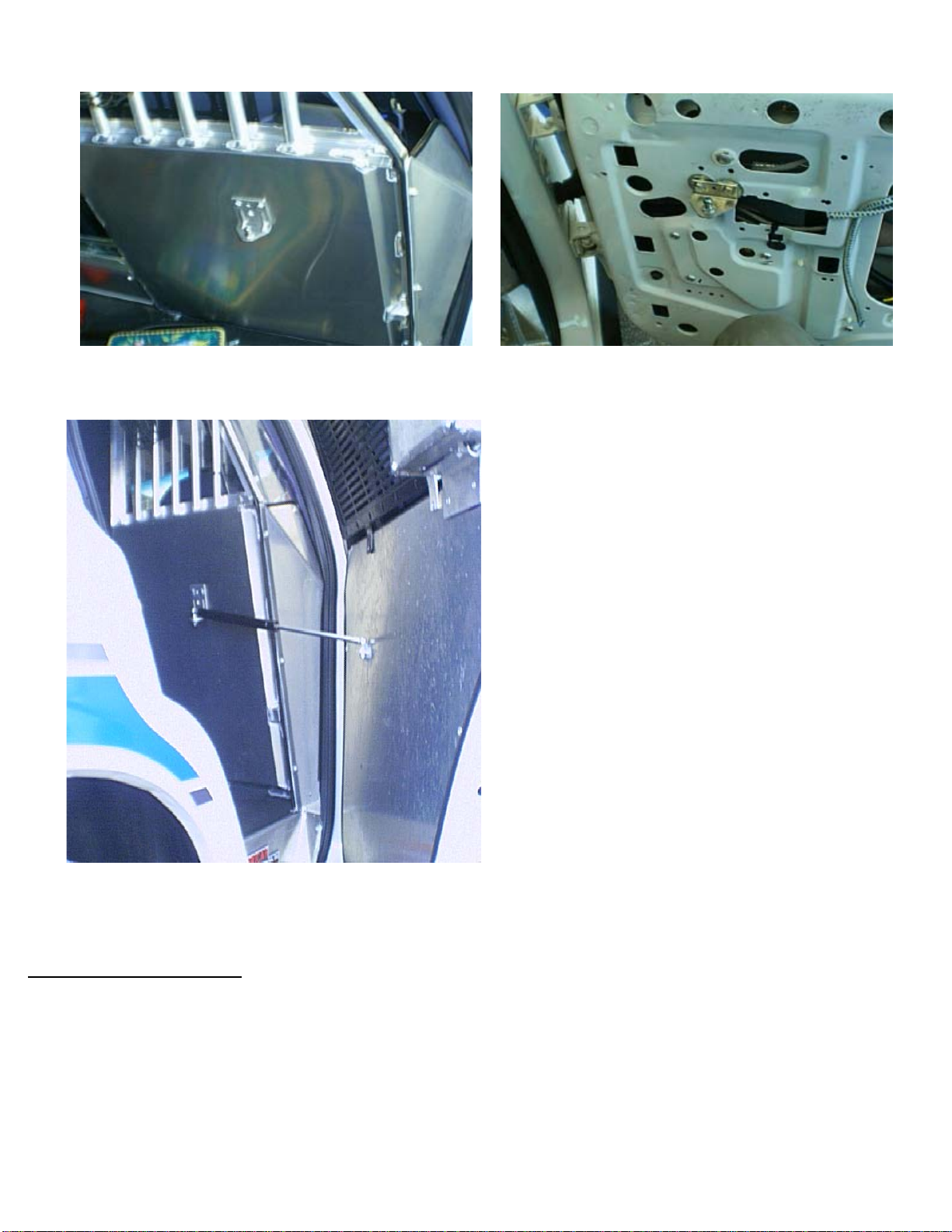
Gas Spring mounted photos in Crown Victoria.
With the door skin removed; enter the vehicle and
close the door that you are attempting to open with
the gas spring. Position the closed spring on the floor
of your cage and examine which location is most
suitable for attaching it to door.
If it is desired to mount the spring on the floor of the
cage, position it as close to the vertical wall behind the
front panel as possible. This will provide a wider
passage area and remove the spring from the K-9's
path while being deployed from the vehicle.
While the door is closed; examine the DOOR FRAME
for an attachment point, usually located midway up the
door frame. You may attach the gas spring to the door
frame with one mounting bolt for testing. Do not drill
the door's interior cover panel prematurely. Make a
small cut in the door panel to allow the door gas spring
bracket to pass through with the ball removed. Drill
two holes in the door frame to temporarily hold the
spring in place while the rear inside mounting position
is being determined. Bolt the spring bracket to the
door frame, but never to the aluminum cover.
Once you are satisfied with the spring position and installation remove the ball, mark your position on the cover, and cut
aluminum/plastic/carpeted door panel. Mount the spring, remount the door panel, and reinstall the ball. Apply silicone
sealant to fill the open hole in the door panel.
Electrical Connections:
It is strongly recommended to double check wire connections for proper termination, shorts, and pinched wires
for clearances before connection to the battery and fuse insertion.
NOTE: Vehicle Manufacturers typically will not provide complete data on the various switching systems for window lock and
unlock functions. Certain vehicles will require a special ground (control) relay to supply ground for these functions. Our system
supplies 12 volts. Chevrolet and Dodge owners/installers pay special attention to your circuits.

Criminalistics, Inc. 7560 NW 82nd St., Miami, FL 33166, (305) 885 6444, Fax (305) 885 3330
1391 Main Ave., Morton, WA 98356, (360) 496 6363, Fax (360) 496 6210
- 10 -
Unlatch Solenoid:
Attach the positive wire from the unlatch solenoid to Premier Canine System™ connector pin #6. This will route the positive 12
Volts DC output necessary to enable the solenoid to unlatch the door. Connect the negative lead of the unlatch solenoid to a
good ground point on the vehicle chassis.
Notes: Most doors have weak or poor vehicle grounds. Also remove paint/coatings from the surface around these connections to
ensure a proper ground has been established. It may be necessary to run the vehicle engine during repetitive testing of the door
opening function of your Premier Canine System™
, to help prevent a low battery voltage condition from interfering with the
testing process. The Premier Canine System™ has a low voltage detection system which will trigger the alarm system.
Electric Door Locks:
Use a voltmeter at the electric door lock actuator inside the door to locate the vehicle positive 12 volt door unlocks trigger
line. The input on the electric lock/unlock actuator reverses polarity depending on the lock/unlock function. Verify that positive
voltage is present during the unlock function. Cut the wire between the unlock switch and the electric door lock actuator. Route
the Red/Black, two-conductor wire provided to the subject door lock. Connect the Red wire to the wire that is attached to the
switch side of the cut wire. Connect the Black wire to the door unlock actuator side of the cut wire.
NOTE: Do not split the Red/Black two-conductor wire, it is recommended to route them together as they are attached.
Electric Windows (A & B):
Use a Voltmeter at the electric window motor inside the door, locate the electric window motor input (positive 12 volts when
the window is rolling down). The input to the electric window motor reverses polarity depending on the function. Verify that
the input that has a positive voltage during the window roll-down function. Cut the wire between the window motor and the
window switch. Make your connection close to the motor. Route the Clear twin lead (Window A, Fan window) and Blue twin
lead (Window B), zip wire provided. Connect the clear zip Copper colored wire to the wire that is attached to the door window
motor. Connect the clear zip Silver colored wire to the switch side of the wire. Connect the blue zip labeled (win B out) wire
to the wire that is attached to the door window motor. Connect the blue zip labeled (win B in) wire to the switch side of the
wire.
NOTE: Proper connections will enable the vehicle window switch system to operate normally when your Premier Canine SystemTM
Plus is not in the alert mode. When your Premier Canine SystemTM Plus system is activated in a heat alert mode, 12 volts will
be present on the copper colored wire(s) for 5 seconds at the beginning of the alert cycle, rolling down the windows
one at a time.
Accessory:
Locate the positive wire of the desired accessory the Premier Canine SystemTM Plus has been designated to activate. The
accessory must require a positive voltage for activation. Route the “Green” accessory wire to the alerting accessory, typically
the horn. Tap into the wire that delivers +12 volts to the accessory. If the horn is used, attach the accessory wire directly to the
horn wire (do not go through the horn relay). Solder and apply heat shrink as necessary.
In case of horns with multiple positive wires: Use a voltmeter to determine which wire is delivering the highest voltage.
Remove wire clip from the horn. Attach positive lead of voltmeter to wire. Touch negative lead to the vehicle's ground and
activate the horn while you read the voltmeter. Repeat the test to measure additional positive reading wires. Attach the green
accessory wire to the input where the highest voltage measurement was recorded.
NOTE: As shipped, your Premier Canine SystemTM Plus control units accessory output is capable of driving ONE DEVICE ONLY.
For example, do not connect to both horn and lights. To activate more than one alerting device you must use independent
switching relays.

Criminalistics, Inc. 7560 NW 82nd St., Miami, FL 33166, (305) 885 6444, Fax (305) 885 3330
1391 Main Ave., Morton, WA 98356, (360) 496 6363, Fax (360) 496 6210
- 11 -
Thermal Probes:
NOTE: The Back Up Heat Sensor must be handled with care. Do NOT mount in a hot area. This sensor will trigger the
heat alert functions of the Premier Canine System™ Plus at 92 to 94 degrees and reset at 91 degrees. Do not mount in an area
that could exceed these temperatures during
normal operation
of the vehicle or in an enclosed console, dashboard, direct
sunlight, or in front of an A/C heater vent.
This is the most critical part of the installation for the K-9 protection system to work properly. The Premier Canine SystemTM Plus
uses two temperature probes: The primary probe, which connects via the 3.5mm rear panel jack, and a backup sensor probe
(gray 8 foot cable) in the wire harness.
The primary probe drives the temperature LCD on the front panel of the Premier Canine SystemTM Plus and records the
maximum and minimum temperatures. The probe should be located in a place that best measures the K-9 environment air
temperature.
Caution should be observed in keeping the probe away from the K-9’s access to it and near heat or air
conditioning sources (vents).
The Backup probe is a safety device that is preset to activate the Premier Canine SystemTM Plus if the K-9 area reaches
approximately 92 degrees F. Since this is a backup probe it should not be placed in close proximity of the primary probe.
Keep
the probe
away from the K-9’s access to it and heat or air conditioning sources (vents).
The backup probe is part of a
detachable 1 foot pigtail, in case it is damaged, for easy and quick field replacement.
VSS/Park+/Park-:
The Premier Canine SystemTM Plus is capable of sensing ONE of the following:
VSS (Vehicle Speed Sensor), a vehicle developed signal, varying amplitude, square wave or sine wave, 20mvpp minimum.
Park +, a positive voltage, 5v or greater, when the vehicle is in Park or Neutral
Park –, a ground when the vehicle is in Park or Neutral
A label is placed on the back of the Premier Canine System
TM
Plus at time of manufacture with its configuration. This
configuration can be changed in the field if necessary.
Vehicle Speed Sensor (VSS) Hookup: (Chart enclosed)
The vehicle speed sensor connection will disable the door latch solenoid if the vehicle is in motion. Please note; the vehicle must
be in motion to test this operation. Consult your service manual for the color code of the VSS or utilize the enclosed charts. If you
are still unable to locate the VSS color code please feel free to contact our engineering staff for assistance. Typical turnaround
time for common vehicles is usually one day or less.
Vehicle Speed Sensor Hookup
The green 16 gauge conductor should be connected to the VSS. Normally the VSS vehicle wire is in the dash wire bundle (which
varies with make and model) or it will need to be passed through the firewall and connected to the Vehicle Speed Sensor.
There is also a rear differential sensor and on the drivers side (two wires entering the rear transmission housing prior the drive
shaft.) The location and wire color combinations may vary depending on the make, model, and year of your vehicle.
Park + or – Hookup
The green 16 gauge conductor should be connected to the park status wire in the dash bundle, shift sensor, MCU, or an installer
supplied switch to detect that the unit is positively shifted to the Park or Neutral position. Park + is a positive voltage, greater
than 5vdc, when the vehicle is in Park or Neutral. Park – is a ground when the vehicle is in Park or Neutral.
Verify the configuration label on the rear of the Premier.
In the event that the configuration label is missing, contact Criminalistics, Inc. for instructions on correctly identifying the
configuration of the unit.
Criminalistics, Inc. 7560 NW 82nd St., Miami, FL 33166, (305) 885 6444, Fax (305) 885 3330
1391 Main Ave., Morton, WA 98356, (360) 496 6363, Fax (360) 496 6210
- 12 -
Antenna Installation:
For ease of installation, and practicality purposes, we recommend mounting the antenna on the trunk lid. Choose a mounting
location that is not between, or next to, other antennas and a minimum of 14 inches away from any other antenna.
Mounting the antenna closer to other antennas can cause damage to the Premier Canine System
TM
Plus’ internal receiver.
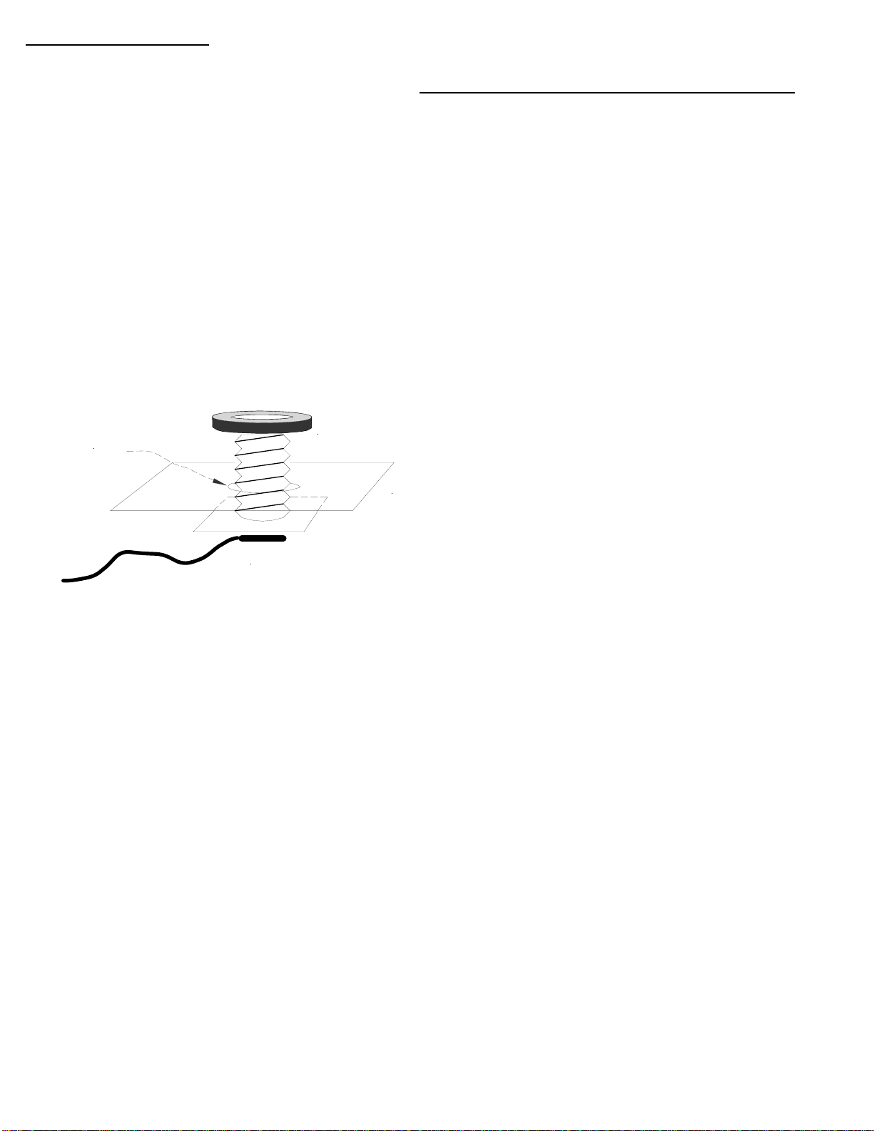
1) Drill a 3/4" hole in the body metal skin of the vehicle at the desired mounting location. Remove padding, or other thick
material, from the inside of the vehicle at least 1/4" from the hole’s edge.
2) Remove all burrs in and around both sides of the hole. Remove paint in a narrow ring around the hole on the underside for
surface contact area. Metal to metal contact between the vehicle and the lower square-cornered mount is essential for the
best performance and range.
3) Remove the circular black insulator nut from the lead. Route the bare end of the cable to the control center and slip the
mounting screw through the hole from the underside. Tighten the black nut while centering the mounting surface from the
underside of the vehicle. Use the enclosed Allen wrench to tighten.
4) Make sure that there is NO metal to metal contact between the center-threaded bolt sticking up and the car metal skin.
This will limit the radio range. All systems are range tested before shipment.
Antenna base stud/coax
Vehicle Skin
Antenna Mount
Nut
(threaded disc)
3/4" Hole
FAILURE TO COMPLY WITH THE ABOVE STEPS CAN AFFECT YOUR RANGE!!!
PLEASE FOLLOW THE INSTRUCTIONS!!!
Criminalistics, Inc. 7560 NW 82nd St., Miami, FL 33166, (305) 885 6444, Fax (305) 885 3330
1391 Main Ave., Morton, WA 98356, (360) 496 6363, Fax (360) 496 6210
- 13 -
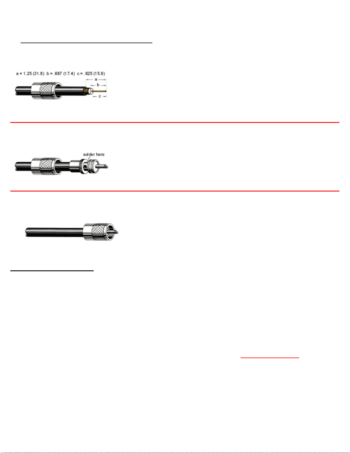
Antenna Connector Instructions:
Step 1
Slide coupling ring onto cable. Cut end of cable even and strip jacket, braid and dielectric
to dimensions shown in table. All cuts are to be sharp and square. Do not nick braid, dielectric or center conductor. Tin exposed
center conductor and braid, avoiding excessive heat.
Step 2
Screw the plug subassembly on cable. Solder assembly to braid through solder holes
making a good bond between braid and shell. Solder conductor to contact. Do not use excessive heat.
Step 3
For final assembly on straight plugs move coupling ring forward and screw in place on plug subassembly.
Final assembly and test:
When everything is complete, connect the system to the battery terminals as mentioned previously to power up your Premier
Canine System™ Plus. Follow the directions enclosed with your antenna carefully. This antenna is cut specifically for your
Premier Canine System™. Poor range can be directly attributed to faulty antenna installation practices. Be sure the
grounding sheath is in no way connected to the signal wire, either at the plug or at the antenna (we recommend verifying this
with an ohm meter). You may now program your Maximum alerting temperature and test the unit.
Continuous pressure on the remote button is not necessary; a single firm press and release will do the job. Failure to heed
these simple instructions will cause damage to the unlatch solenoid.
NOTE: Failure to follow the installation guide: drilling into or opening the control unit, removal of any screws,
improper mounting of the solenoid, or abusive use of the Premier Canine System™ voids the warranty. Please do not
remove mounting brackets and/or reinsert the screws. You can pierce the circuit board causing permanent damage to your
system.
Criminalistics, Inc. 7560 NW 82nd St., Miami, FL 33166, (305) 885 6444, Fax (305) 885 3330
1391 Main Ave., Morton, WA 98356, (360) 496 6363, Fax (360) 496 6210
- 14 -
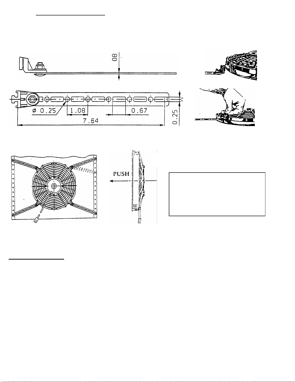
Fan Mounting Overview
Mounting Bracket Kit Mounting brackets - slide into place
Consists of 4 brackets, 4 rods, and 4 fixing bolts. on 4 locations around the fan.
General Operation:
When the system fan is turned on manually (not an alarm condition) it will run at either high or a lower preset speed. You must
flip the toggle switch left for high and right for lower. Center is off.
If the fan is triggered by the Premier, it will run at “High Speed” only until the temperature falls below the high temperature set
point or if Premier control box is switched off.
Note:
If the Premier control unit is in an alarm condition it is not possible to override fan speed control with the manual front
panel switch.
Air Flow Direction
T
he Brackets and rods are ad
j
ustable
and facilitate the most convenient
position for mounting.
The chart above depicts the max diameter
that can be connected with the mounting
kit and size of fan selected. Example: a 10”
fan with mounting brackets attached can
span a maximum area of 25 inches.
Fan Diameter Max. diameter
that can be joined
10” 25”
14” 30”

Criminalistics, Inc. 7560 NW 82nd St., Miami, FL 33166, (305) 885 6444, Fax (305) 885 3330
1391 Main Ave., Morton, WA 98356, (360) 496 6363, Fax (360) 496 6210
- 15 -
Mounting of the Thin Fan:
The Maxi Thin Fan can be surface mounted to the dog cage or window grill covers.
1) Remove the front metal grill cover from the Maxi Thin Fan.
2) Remove the mounting bracket kit (if attached to the fan).
3) Find the desired location on the metal window grill (on the glass side) so that it will leave enough room for the window to
freely move up and down without hitting the fan.
4) Place one flat washer between the fan and the grill for each of the four mounting bracket holes.
5) Place one flat washer on the top of the fan-mounting hole to protect the mounting bracket holes from damage.
6) Use four nuts and bolts to secure the fan to the window grill.
7) Utilize a flat washer on the mounting bolt to prevent it from going through the grill.
8) It may be necessary to notch the top of the door cover in order to run the Maxi Thin Fan power wires to the control unit
through the door cavity and boot. Be sure to route the fan wires so that they are out of the K-9’s reach.
9) Secure the wiring to the grill with tie wraps as needed to prevent them from being damaged.
10) Connect the Deutsch 2 pin connector to the fan power cable connector. A de-pinning tool is provided, in case the connector
is too large for routing. If the pins are removed, re-insert the pins in the correct positions. (red to blue, black to black)
Maxi Thin Fan (Mounted directly to window grill)

Criminalistics, Inc. 7560 NW 82nd St., Miami, FL 33166, (305) 885 6444, Fax (305) 885 3330
1391 Main Ave., Morton, WA 98356, (360) 496 6363, Fax (360) 496 6210
- 16 -
Troubleshooting Guide
Warning: If the unit has been engaged with a temperature reading above 94o F, the backup sensor must be cooled below 91oF before it will
reset. Failure to do so will result in the unit deploying continuously until it can be reset.
To disarm or turn off the Premier Canine SystemTM Plus: Toggle the upper Right hand switch to the center position.
Testing the Premier Canine SystemTM Plus: If you set the High alarm temperature to around 85o F, you should be able to
activate the system with body heat generated in the palm of your hand. Hold the primary probe in your hand and observe the
temperature increase on the front panel LCD. When the temperature reaches your high programmed temperature, your alerting
system will be triggered, displaying MAX on the LCD screen accompanied by a blinking green LED. You can manually deactivate
the system
by toggling the upper right-hand switch to the center (OFF) position.
Symptom or Issue Possible Causes / Solutions
Display is jumpy, reads erratically
Programming set point changes.
Alarm does not sound
Digital display is locked up. Stuck on one
temperature or will not program to desired setting.
Alarm remains on
Display reading is LLL
Display reading is HHH
No Displayed Temperature
Fuse is blown or blows upon alerting.
Unit has engaged without reaching maximum
Temperature
Improper grounding of the unit. Check your ground wire. Make
sure system is grounded to the car battery!
Control Unit and/or probe are too close to radio transmitter.
Battery has lost power or has been disconnected. Loose battery
connection.
Set point is programmed improperly. Go through programming
instructions again. If "MAX" is flashing and your horn, lights or
siren are not activated, improper connections could be the culprit.
The unit has received a power surge. Turn the unit off and remove the
fuse (at vehicle battery). Let the system discharge for about 30 minutes or
more. Replace the fuse and reset the system. Set point is programmed
improperly. Make sure setting is 75oF or higher (must be higher than
ambient room temperature in your current location). Back up probe may
have been activated, If the temperature has exceeded 94o, cool physical
body of back up sensor below 91oF for it to reset. You may use a freeze
spray to accomplish this quickly.
If your display reads LLL and will not return to any numbered
reading, the primary probe wire may be broken or disconnected.
You may want to consider ordering a spare probe to avoid this
situation.
The temperature has exceeded 200oF. This can be observed
when you are both out of the vehicle and the system is not
enabled. Cool the vehicle off and the reading will return. Check
for proper installation of the probe.
Internal rechargeable NiMh battery is discharged; Turn on the
premier for approximately 8 hours to recharge the battery.
Short in output control wires, windows or latch solenoid
Please contact us with any questions. We are here to assist you.

Criminalistics, Inc. 7560 NW 82nd St., Miami, FL 33166, (305) 885 6444, Fax (305) 885 3330
1391 Main Ave., Morton, WA 98356, (360) 496 6363, Fax (360) 496 6210
- 17 -
Final Notes
Make sure that the system ground is connected to
ground terminal of vehicle battery. Improper grounding will adversely
affect the unit. After everything is complete, and the final battery connection has been made, power up your Premier
Canine System™ Plus. Make sure a maximum temperature is programmed.
Ensure that the locations designated for both of the system's primary and back up temperature probes are
not in direct sunlight or over/under the vehicle's heater vents, thus causing false alerts. Be mindful that
chewed, eaten, snatched, cut, or otherwise damaged probes are not covered by the warranty.
Please test your system daily
. When you enter the vehicle at the beginning of a shift and the vehicle is still hot, flip
the Premier Canine System™ Plus on and check to make sure it alerts. Do not assume that the vehicle or system has not
been altered during your time away. This could result in deadly consequences.
You will lose your high setting maximum temperature set point if the LCD does not display ambient
temperature. Should this occur, simply reprogram the unit by following the programming instructions. Also, ensure that
the control system is connected directly to the battery enabling power at all times, even when the car is not running.
Some vehicles will shut down the accessory fuse block if they are overheating. Always connect to vehicle battery with the
supplied fuse link. A minimum 30 amp fuse is required, but 40 amps is recommended.
Should you should ever have to jump start your vehicle, provide someone with a jump, or need to charge the vehicle
battery, you must turn the Premier control unit off prior. Failure to turn the unit off may send a power surge to the
unit and cause the system damage.
Carefully follow the instructions enclosed with your antenna. This antenna is designed and cut specifically for your
Premier Canine System™ Plus. Degradation of range can usually be attributed to faulty antenna installation practices.
Ensure that the grounding sheath does not come in contact with the signal wire at either the plug or at the antenna base.
A continuity tester can verify this. Poor antenna installation practices can decrease normal range for your remote door
opener.
Limited Warranty
Criminalistics, Inc. warrants your Premier Canine SystemTM Plus system to be free from defects in materials and
workmanship for a period of one year from date of sale to the original purchaser. Criminalistics, Inc. will repair this
product, free of charge, when product is returned, at customer expense, to Criminalistics, Inc. and if, in the judgment of
our staff, said product has proven to be defective within the warranty period. This warranty does not cover any expenses
incurred in the removal and reinstallation of this product.
This warranty does not apply to any product damaged by improper installation, accident, misuse, abuse,
improper line voltage, fire, flood, lightning or other acts of God, or if the product was altered or repaired by anyone other
than
Criminalistics, Inc.
NOTE: Failure to follow installation guide, drilling into, opening the control unit, removal of any screws, improper
mounting of the solenoid, or abusive use of the Premier Canine SystemTM Plus voids the warranty. It is not necessary to
hold down the button on the remote; a single firm press and release will do the job. Failure to comply with these
instructions can damage the unlatch solenoid.
Criminalistics, Inc. shall have no liability for any death, personal and/or bodily injury, and/or damage to property or
other loss whether direct, indirect, incidental, consequential, or otherwise, based on a claim that the product
malfunctioned. However, if we are held liable, whether directly or indirectly, for any loss or damage arising under this
limited warranty or otherwise, regardless of cause or origin, our maximum liability shall not in any case exceed the
purchase price of the product.
Thank you for purchasing Criminalistics, Inc. Products
Please keep this Warranty Statement with your Invoice
Table of contents
Popular Door Opening System manuals by other brands

Assa Abloy
Assa Abloy 78PRA-8L installation instructions

Assa Abloy
Assa Abloy Norton PR7500 installation instructions

Allegion
Allegion Briton 3934 Fixing instructions

Dorma
Dorma RSP 80 Mounting instruction

Mobotix
Mobotix DoorMaster MX-Door2-INT Quick install

Siemens
Siemens 3VL9800-3A 0 Series operating instructions


