Eco SR User manual

ECO Schulte GmbH & Co. KG
Iserlohner Landstraße 89
D-58706 Menden
3-6 01 13 8
06
0432 - CPD - 0147 EN 1158:1997+A1:2002
1/10
GS
DIN rechts - spiegelbildlich
DIN right - mirror image
DIN droite - inverser l´illustration
Abkürzungen
Schließ-
geschwindigkeit
SG
ES
SK
Endschlag
Schließkraft
CS
Abbrevations Abrévations
Closing speed
LS
CF
Latching speed
Closing force
Vitesse de
fermeture
VF
CF
FF
Coup final
Force de
fermeture
950 mm 0
1100 mm +5
1750 mm -7
850 mm -4
Türschließergröße
Door closer size
Force de ferme porte
Max. Türbreite
Max. door width
Largeur de porte max.
Umdrehungen
Rotations
Rotations
2
3
4
TS-41
EN 1-4
max.
3,5mm
950 mm 0
TS-31
EN 1-3
1750 mm -11
850 mm
Türschließergröße
Door closer size
Force de ferme porte
Max. Türbreite
Max. door width
Largeur de porte max.
Umdrehungen
Rotations
Rotations
2
3
-6
ECO Schulte GmbH & Co. KG
Iserlohner Landstraße 89
D-58706 Menden
0432 - CPD - 0031
10
1-3 3
1 1
4 8
1-4 3
1 1
4 8
EN 1154:1996+A1:2002
Leistungserklärung nach Verordnung (EU) Nr. 305/2011 finden Sie unter http://www.eco-schulte.de/leistungserklaerungen
Declaration of performance according to Regulation (EU) No 305/2011 see http://www.eco-schulte.de/declarationofperformance
Déclaration des performances conformément au règlement (UE) N° 305/2011 voir http://www.eco-schulte.de/declarationdesperformances
Only original parts have to be used. The assembly has to be made by a qualified person according to the mounting instruction. In case of
non-respect the guarantee is invalid. This instruction is to be handed over to the operator by the fitter after assembly!
Impérativement utiliser la notice de montage fournie par le fabricant. La mise en œuvre et le montage doivent être exécutés par du person-
nel qualifié. Le non respect de ces règles annule catégoriquement tout droit de garantie Cette instruction est à remettre par le poseur
à l’exploitant après montage.
Für die Montage dürfen ausschließlich Originalteile des Herstellers verwendet werden. Die Montagearbeiten müssen gemäß Anleitung von
einer qualifizierten Person durchgeführt werden. Bei Nichtbeachtung entfällt jeglicher Garantieanspruch. Diese Anleitung ist vom Monteur
nach der Montage an den Betreiber weiterzugeben!

M5x20
4,5x30
M5x20
4,5x30
2
2
1
1
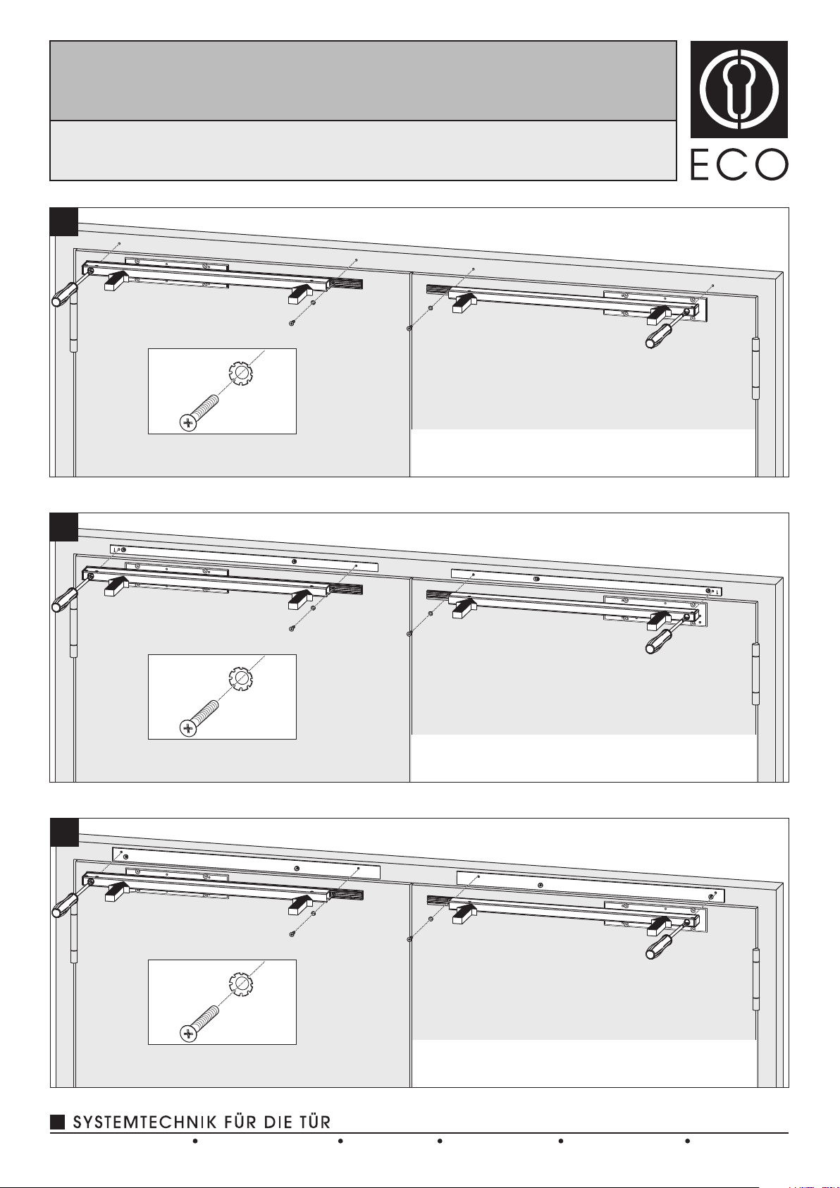
Montage mit Adaptionsprofil 30mm (Lochgruppe 120/428,5mm)
Mounting with adaptor plate 30mm (hole group 120/428,5mm)
Montage avec 30mm (group de trous 120/428,5mm)profil d’adaptation
(optional, optional, optionnelle)
M5x20
4,5x30
M5x20
4,5x30
1
1
2
2
Direktmontage (ohne Unterprofil)
Direct mounting (without underprofile)
Montage direct (sans sous profil)
M5x20
4,5x30 M5x20
4,5x30
2/10
1b
1c
1a
Montage mit Standardprofil 20mm (Lochgruppe 120/428,5mm)
Mounting with standardprofile 20mm (hole group 120/428,5mm)
Montage avec profil standard 20mm (group de trous 120/428,5mm)
(optional, optional, optionnelle)
www.eco-schulte.deTel. +49 2373 9276-0D-58706 MendenIserlohner Landstraße 89
ECO Schulte GmbH & Co. KG Fax +49 2373 9276-40
SR mit / with / avec TS-31/41
Montageanleitung / Assembly instruction / Notice de montage
DIN links / left / gauche
DIN rechts / right / droite
3/10
2b
2a
2c
Montage mit Adaptionsprofil 30mm (Lochgruppe 120/428,5mm)
Mounting with adaptor plate 30mm (hole group 120/428,5mm)
Montage avec 30mm (group de trous 120/428,5mm)profil d’adaptation
Direktmontage (ohne Unterprofil)
Direct mounting (without underprofile)
Montage direct (sans sous profil)
Montage mit Standardprofil 20mm (Lochgruppe 120/428,5mm)
Mounting with standardprofile 20mm (hole group 120/428,5mm)
Montage avec profil standard 20mm (group de trous 120/428,5mm)
(optional, optional, optionnelle)
(optional, optional, optionnelle)
www.eco-schulte.deTel. +49 2373 9276-0D-58706 MendenIserlohner Landstraße 89
ECO Schulte GmbH & Co. KG Fax +49 2373 9276-40
SR mit / with / avec TS-31/41
Montageanleitung / Assembly instruction / Notice de montage
DIN links / left / gauche
DIN rechts / right / droite
3
2
1
2SG/CS/VF 2
1
SG/CS/VF
SW 2,5
3
2
4/10
4
5
SK/CF/FF
SK/CF/FF
EN 1-3
1
+
TS-31
-6
-11
EN
2
mm
850
750
+
5
56
03 950
1
+
+
3
25
TS-41 EN 1-4
+5
-7
-4
0
EN
2
3
4
mm
850
750
950
1100
1
M6x20 1
22
3
1-3
8
0432-CPD-0031
TS-31
1 1 3
4
EN1154:1996+ A1:2002
2010
1
+
TS-31
-6
-11
EN
2
mm
850
750
+
3
13
03 950
+
+
3
13
TS-31
EN
mm
+
+
3
14
TS-41
EN
mm
+
+
3
13
TS-31
EN
mm
+
+
3
14
TS-41
EN
mm
1-3
8
0432-CPD-0031
TS-31
1 1 3
4
EN1154:1996+ A1:2002
2010
1
+
TS-31
-6
-11
EN
2
mm
850
750
+
3
13
03 950
1-3
8
0432-CPD-0031
TS-31
1 1 3
4
EN1154:1996+ A1:2002
2010
1
+
TS-31
-6
-11
EN
2
mm
850
750
+
3
13
03 950
1-3
8
0432-CPD-0031
TS-31
1 1 3
4
EN1154:1996+ A1:2002
2010
1
+
TS-31
-6
-11
EN
2
mm
850
750
+
3
13
03 950
M5x40
4,5x70
M5x40
4,5x70
www.eco-schulte.deTel. +49 2373 9276-0D-58706 MendenIserlohner Landstraße 89
ECO Schulte GmbH & Co. KG Fax +49 2373 9276-40
SR mit / with / avec TS-31/41
Montageanleitung / Assembly instruction / Notice de montage
DIN links / left / gauche
DIN rechts / right / droite
X
X + 28 mm
2
X
1
ES/LS/CF
1
10°-0°
SG/CS/VF
2
180°-0°
5/10
6
7
8
2
2
1
1
www.eco-schulte.deTel. +49 2373 9276-0D-58706 MendenIserlohner Landstraße 89
ECO Schulte GmbH & Co. KG Fax +49 2373 9276-40
SR mit / with / avec TS-31/41
Montageanleitung / Assembly instruction / Notice de montage
DIN links / left / gauche
DIN rechts / right / droite

1
Funktionsprüfung SR
Functional test SR
Test fonctionnel SR
22x 2
Y
Y - 8 mm
2
Y
1
3
1
90°
2
SW2,5
2x
4
SW2,5
2x
9
10
11
6/10
www.eco-schulte.deTel. +49 2373 9276-0D-58706 MendenIserlohner Landstraße 89
ECO Schulte GmbH & Co. KG Fax +49 2373 9276-40
SR mit / with / avec TS-31/41
Montageanleitung / Assembly instruction / Notice de montage
DIN links / left / gauche
DIN rechts / right / droite

1
1
3
3
2
2
12
13
14
7/10
www.eco-schulte.deTel. +49 2373 9276-0D-58706 MendenIserlohner Landstraße 89
ECO Schulte GmbH & Co. KG Fax +49 2373 9276-40
SR mit / with / avec TS-31/41
Montageanleitung / Assembly instruction / Notice de montage
DIN links / left / gauche
DIN rechts / right / droite
1b
2a
1
3
4
5
6
7
8
9
10
Bohrschablone anlegen und je nach Anbauvariante (Direktmontage, Montage mit Standardprofil oder Montage
mit Adaptionsprofil) Bohrlochgruppe wählen und Locher bohren.
Standardprofile (optional) anschrauben, gegebenenfalls bei Überlappung in Türmitte kürzen .
(Türschließer) anschrauben .
Montageplatten
Montageplatten (Türschließer) anschrauben.
Gangflügelgleitschiene und Standflügelgleitschiene direkt montieren.
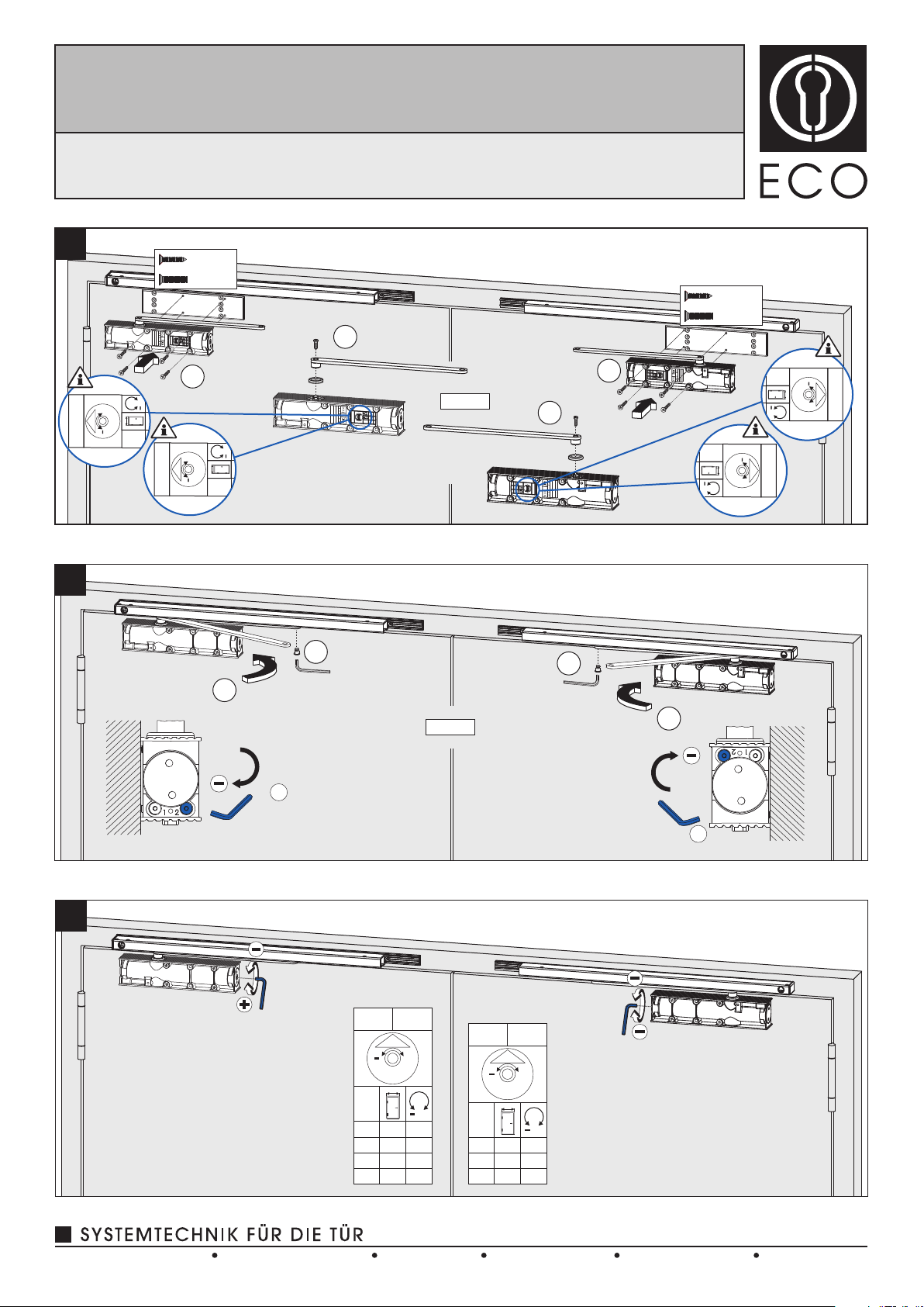
Hebelarme mit Türschließer verbinden . Türschließer montieren .
12
Schließgeschwindigkeitsventile schließen . Die Hebelarme Richtung Gleitschiene führen und mit den
Gleitschienen verbinden . Schließgeschwindigkeitsventile wieder öffnen, Türen schließen.
12
3
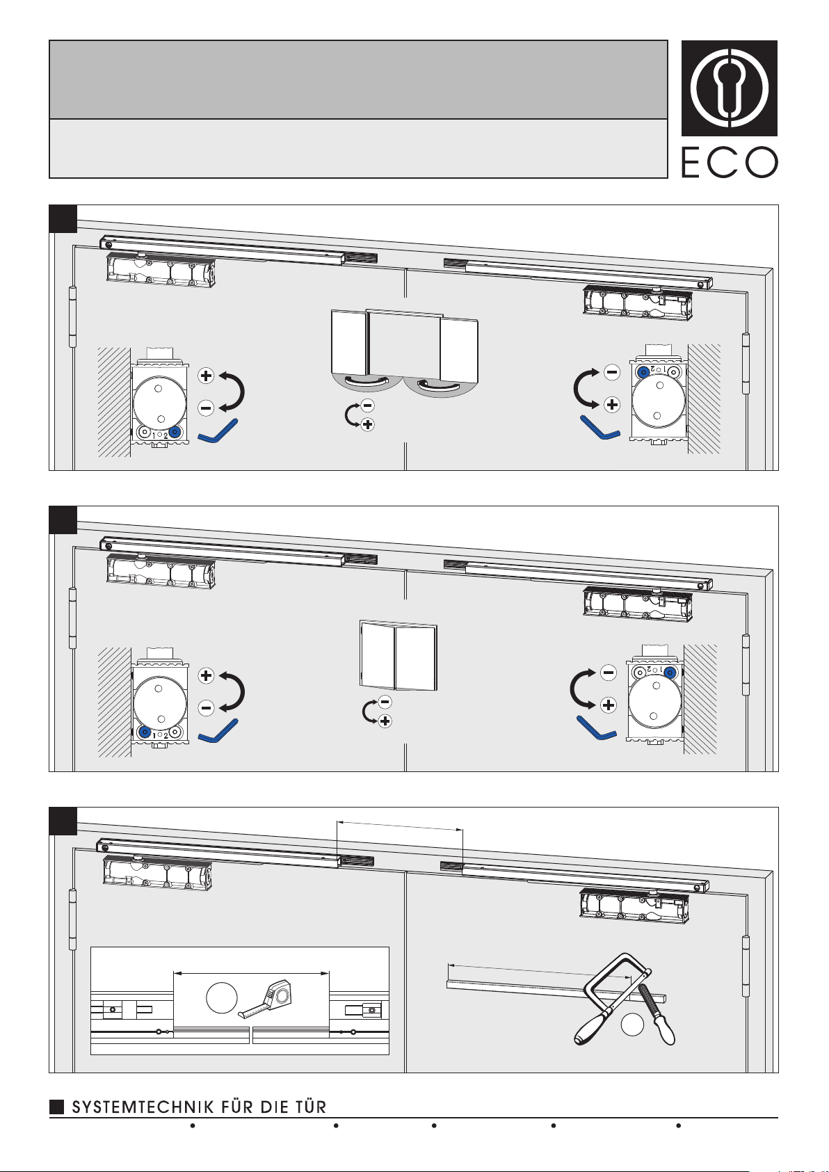
Schließgeschwindigkeit einstellen.
Schließkraft einstellen.
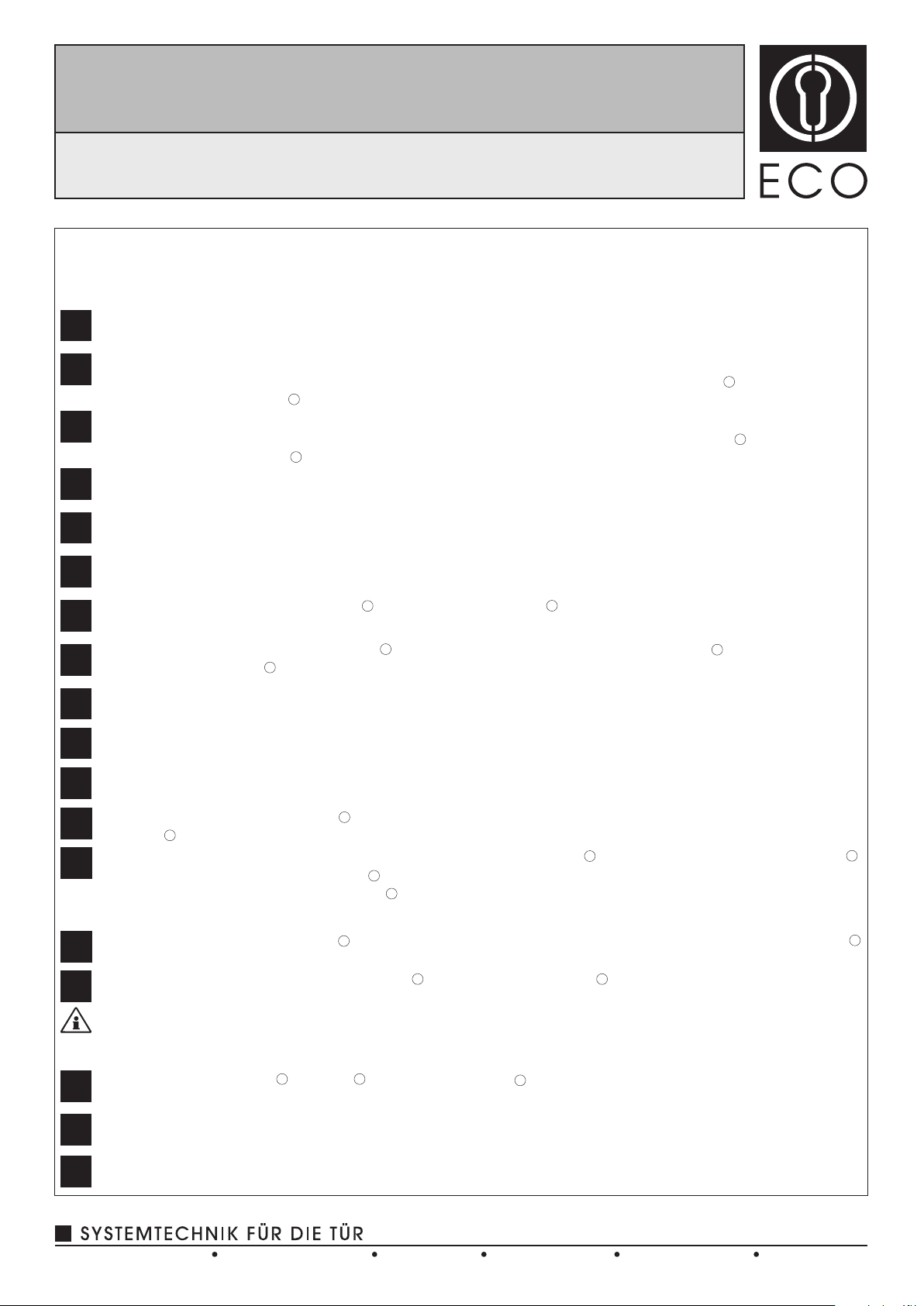
Maß x gemäß Darstellung ermitteln . Verbindungsstange auf entsprechendes Maß x+28mm ablängen und
entgraten .
2
11
12
13
14
Verbindungsmuffen wie dargestellt auf die Verbindungsstange schieben . Verbindungsstange um 90° drehen
und zwischen die Stangenenden führen . Die Verbindungsmuffen über die Stangenenden auf Anschlag
schieben und Madenschrauben festziehen . Wichtig: Die Schrauben der Verbindungsmuffen müssen nach
unten zeigen.
12
3
4
Maß y gemäß Darstellung ermitteln . Abdeckprofil auf entsprechendes Maß y - 8mm ablängen und entgraten .
12
Abdeckprofil auf das Montageprofil einhängen , ausrichten und fixieren .
12
Funktionsprüfung SR
Beide Türen ca. 60° öffnen, Gangflügel muss geöffnet bleiben. Standflügel schließt. Gangflügel darf erst ab
einem Schließwinkel des Standflügels von ca. 30° schließen.
Kunststoff-Clips einsetzen . U-Cover und Ritzelabdeckung am Türschließer aufklippen.
123
Schraublochabdeckungen in die Gleitschienen klippen.
Direktmontage
1a
Montage mit Standardprofil
1c Montage mit Adaptionsprofil
1
2
Adaptionsprofile (optional) anschrauben, gegebenenfalls bei Überlappung in Türmitte kürzen .
(Türschließer) anschrauben .
Montageplatten
1
2
Direktmontage
2b Gangflügelgleitschiene und Standflügelgleitschiene auf die Standardprofile schrauben.
2c Gangflügelgleitschiene und Standflügelgleitschiene auf die Adaptionsprofile schrauben.
Montage mit Standardprofil
Montage mit Adaptionsprofil
Endschlag einstellen.
Im Folgenden wird die Montage für Gangflügel links gezeigt. Bei Gangflügel rechts bitte entsprechend spiegelbildlich vorgehen.
Gleitschiene mit Türschließer fertig montiert.
8/10
www.eco-schulte.deTel. +49 2373 9276-0D-58706 MendenIserlohner Landstraße 89
ECO Schulte GmbH & Co. KG Fax +49 2373 9276-40
SR mit / with / avec TS-31/41
Montageanleitung / Assembly instruction / Notice de montage
DIN links / left / gauche
DIN rechts / right / droite

Assembly for active leaves on the left is described below. For active leaves on the right, please proceed accordingly.
Attach drilling template and choose corresponding drill holes depending on mounting situation (direct mounting,
mounting with standard profile or mounting with adaptor plate). Drill holes.
Screw on standard profiles (optional), shorten if necessary .Screw on door closer mounting plates .
Mount active leaf slide rail and passive leaf slide rail directly.
Direct mounting
Mounting with standard profile
Mounting with adaptor plate
Screw on door closer mounting plates.
12
Screw on adaptor plate (optional), shorten if necessary .Screw on door closer mounting plates .
12
Direct mounting
Mounting with standard profile
Mounting with adaptor plate
Mount active leaf slide rail and passive leaf slide rail onto standard profile.
Mount active leaf slide rail and passive leaf slide rail onto adaptor plate.
Connect lever arms to door closer . Fit door closer .
Close closing speed valve . Guide the lever arm in the direction of the slide rail and connect to the slide rai .
Open speed valves. Close doors.
Set closing force.
12
123
Set closing speed.
Set latching speed.
Determine dimension x in line with drawing . Cut connecting rod to length in line with said dimension
x + 28 mm and trim .
Push coupling sleeves as depicted onto the connecting rod . Turn the connecting rod by 90° .Push connecting
rod between the rod ends . Push the coupling sleeves over the rod ends and tighten grub screws . Attention:
the screws of the coupling sleeves have to point downwards.
1
2
12
34
1b
2a
3
4
5
6
7
8
9
10
11
12
13
14
1a
1c
2b
2c
Determine dimension y acc. to drawing . Cut to length the U-cover profile to dimension y - 8mm and deburr the
cover profile .
Attach cover profile to mounting profile , adjust it and fix it .
Functionality test SR
Open both doors approx. 60°, active leaf has to remain open. Passive leaf closes. Active leaf is only allowed to
close if the passive leaf reaches a closing angle of approx. 30°.
Attach nylon clips . Clip on U-Cover and pinion cover .
Clip on covers for drill holes in slide rail.
1
2
12
123
9/10
Slide rail and door closer mounted.
www.eco-schulte.deTel. +49 2373 9276-0D-58706 MendenIserlohner Landstraße 89
ECO Schulte GmbH & Co. KG Fax +49 2373 9276-40
SR mit / with / avec TS-31/41
Montageanleitung / Assembly instruction / Notice de montage
DIN links / left / gauche
DIN rechts / right / droite

Ci-dessous le montage pour vantail principal gauche. Pour le montage à droite veuillez procéder en conséquence.
Positionner le gabarit de perçage et selon le cas de configuration (montage direct, montage avec profile standard ou
avec profil d’adaptation) choisir les trous adaptés puis perçer.
Montage direct
Montage avec profil standard
Montage avec profil d’adaptation
Fixer la plaque de montage du ferme-porte.
Fixer le profile standard (en option) recouper si necessaire . Fixer la plaque de montage du ferme-porte .
Fixer la plaque d’adaptation (en option) recouper si necessaire . Fixer la plaque de montage du ferme-porte .
Fixer la glissière du vantail principal et du vantail secondaire sur le profile d´adaption.
Fixer le bras au ferme-portes . Fixer le ferme-portes .
Fermer la valve du réglage de la vitesse . Positionner le bras jusqu’au patin de la glissière puis visser le bras
au patin . Ouvrir la valve du réglage de la vitesse. Fermer les portes.
12
12
3
Ajuster la force fermeture.
Prendre la mesure X comme indiqué . Recouper et ébavurer la tige à la dimension X+28mm .
Positionner comme indiqué les manchons de raccordement sur la tige . Tourner la tige de 90° , positionner
et fixer les manchons à l’aide des vis 6 pans creuses . (les vis doivent être dirigées vers le bas).
12
123
4
12
12
Fixer la glissière du vantail principal et du vantail secondaire direct.
Fixer la glissière du vantail principal et du vantail secondaire sur le profile standard.
Ajuster la vitesse de fermeture.
Ajuster l’à-coup final.
1b
2a
3
4
5
6
7
8
9
10
11
12
13
14
1a
1c
2b
2c
Montage direct
Montage avec profil standard
Montage avec profil d’adaptation
Prendre la mesure Y comme indiqué . Recouper et ébavurer la tige à la dimension Y - 8mm .
Test du sélecteur.
Ouvrir les deux vantaux à 60°, le vantail principal doit se maintenir en position ouverte. Le vantail secondaire doit
se fermer. Le vantail principal doit se fermer à partir d’un angle de fermeture du vantail secondaire à partir de
30°.
Positionner les clips plastique . Clipser le capot U du ferme-portes ainsi que le cache de l’axe .
Clipser les caches-vis de la glissière.
12
123
12
Accrocher, ajuster et fixer le profil de recouvrement sur le profil de montage - .
Monter la glissière et le ferme-portes.
10/10
www.eco-schulte.deTel. +49 2373 9276-0D-58706 MendenIserlohner Landstraße 89
ECO Schulte GmbH & Co. KG Fax +49 2373 9276-40
SR mit / with / avec TS-31/41
Montageanleitung / Assembly instruction / Notice de montage
DIN links / left / gauche
DIN rechts / right / droite
This manual suits for next models
2
Other Eco Door Opening System manuals


 User manual")


Popular Door Opening System manuals by other brands


 manual")


Record
Record DFA 127 user manual

Nabco
Nabco GT20 Programming manual

CornellCookson
CornellCookson AlarmGard FST-EPBD Series Installation instructions and operation manual

DDS
DDS 2300CA Series Operation and maintenance manual

PDQ
PDQ 3100 Instruction

Cal-Royal
Cal-Royal CR801 Series installation instructions

Nabco
Nabco GYRO TECH GT-1175 Wiring and Programming Manual

Dorma
Dorma COMFORTDRIVE Moveo Original Operating Instruction Manual

Fireco
Fireco Dorgard Pro Handbook

GEZE
GEZE Slimdrive EMD-F Installation and service instructions

GEZE
GEZE Perlan AUT-NT Mounting instructions

Woodhaven
Woodhaven 4516 quick start guide