manuals.online logo
Brands
  1. Home
  2. •
  3. Brands
  4. •
  5. Yale
  6. •
  7. Door Opening System
  8. •
  9. Yale UNI-TJ50BC Series User manual

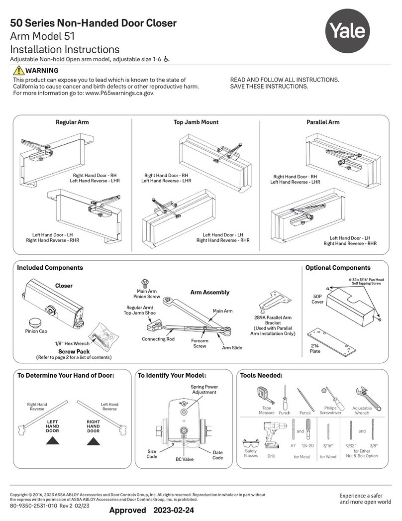
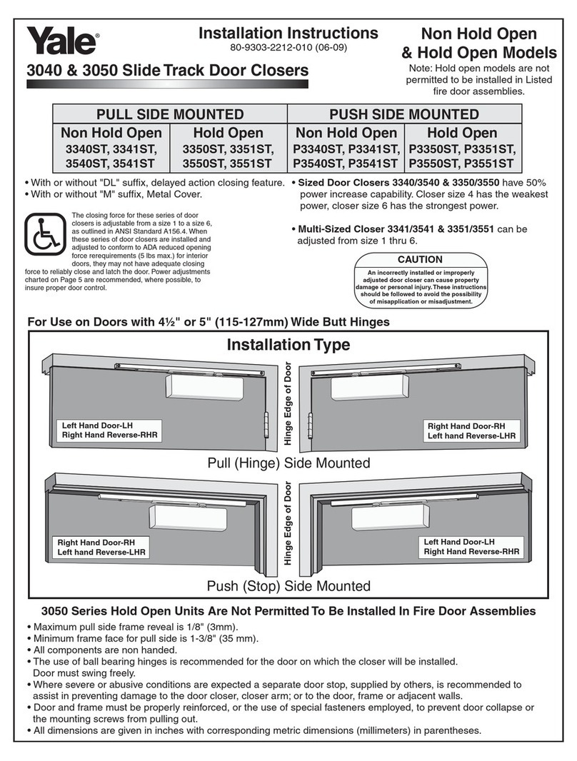
Yale UNI-TJ50BC Series User manual

UNI Stop/Holder
UNI-TJ50BC Series
UNI-TJ51(BF) Series
Sized Closers
Multi-Sized Closers
Installation Instructions
80-9350-2517-010 (06-09)
Non Handed Door Closers Sized
(Sizes 2,3,4,5,6)
UNI-TJ52BC UNI-TJ152BC
UNI-TJ53BC UNI-TJ153BC
UNI-TJ54BC UNI-TJ154BC
UNI-TJ55BC UNI-TJ155BC
UNI-TJ56BC UNI-TJ156BC
Multi-Sized
(Sizes 3 thru 6)
UNI-TJ51
UNI-TJ151
(Sizes 1 thru 4)
UNI-TJ51BF
UNI-TJ151BF
CAUTION
AN INCORRECTLY INSTALLED OR IMPROPERLY
ADJUSTED DOOR CLOSER CAN CAUSE
PROPERTY DAMAGE OR PERSONAL INJURY.
THESE INSTALLATION INSTRUCTIONS SHOULD
BE FOLLOWED TO AVOID THE POSSIBILITY OF
MISAPPLICATION OR MISADJUSTMENT.
CAUTION
!
!
!
!
NOTE: For special applications a separate door and frame preparation template is packed with these instruction. Use this
instruction sheet for installation sequence and closer adjustments only.
It is recommended that the door, on which the door closer will be installed, be hung on ball bearing hinges. Door must swing
freely.
Door and Frame must be properly reinforced, or use of special fasteners employed, to prevent the mounting screws from pulling
out.
All dimensions are given in inches with corresponding metric dimensions (millimeters) in parenthesis.
Right Hand Door - RH
Left Hand Reverse - LHR
Hinge edge of door
Left Hand Door - LH
Right Hand Reverse - RHR
Right Hand Door - RH
Left Hand Reverse - LHR
Left Hand Door - LH
Right Hand Reverse - RHR
Components
Pinion Cap
Power Adjustment Screw (3/16 Hex Drive)
“BC” Valve
Closer
Size
Stamp
“L” Valve “S” Valve
Optional Cover
Hinge edge of door
Hinge edge of door
Hinge edge of door
Non Hold Open &
Hold Open (TJ150) Models
Series UNI-TJ50
UL Listed for Fire Doors
Door Stop...Door Closer
Series UNI-TJ150
(On-Off Hold-Open Control) Not UL Listed
Door Stop...Door Holder...Door Closer
2 sex-nuts
Holder Control
Slide Unit
Rod Screws
Main-Arm
Screw
Rod Unit
(Arm Number
Stamp)
Optional Thru-Bolt
&
Grommet Nuts
These installation instructions cover either of the models illustrated.
Page 2
80-9350-2517-010 (06-09)
Hollow-Metal or Wood Openings
Template
Hinge
Side Elevation
Opening Dimension “A”
inches mm.
9-1/8
8-3/8
7-3/4
232
213
197
Installation Sequence
51 and 51BF Models Only. Set closing power using
“Power Adjustment Chart”at bottom of page 3.
!
!
!
!
!
!
!
!
!
!
!
This page for installation on hollow-metal or wood. For
aluminum doors and frame use page 3.
Select door opening angle using template above. Mark 4
holes on frame face for closer and 2 holes on door for arm
foot.
Prepare door and frame for fasteners. See “Preparation
for Fasteners” below.
Install closer to frame face with 2 regulating valves toward
hinge edge of door.
Remove rod unit from arm assembly.
Install main arm onto closer pinion shaft, indexing main
arm mark “S”with Pinion flat as shown at right. Fasten with
arm screw.
Mount arm foot to door. Position foot with rod on top.
Reassemble arm. Adjust forearm perpendicular (at a 90
angle) to door. Tighten rod screws.
Snap pinion cap in place.
Adjust closer.
°
Typical Installation
9/32” (7.00mm.) thru...
3/8” (9.50mm.) door face
opposite to closer
#7 (.201” dia.) or 5.10mm. drill...
1/4-20 tap
3/8” (9.50mm.) thu
3/16” (4.30mm.)
Drill
aluminum
or wood
Hollow-
metal
Frame
metal
wood
1/4”-20
machine screw
#14 type “A” sheet
metal screw
Fasteners
Door
Does not
apply SNB
Does not
apply
Preparation for Fasteners
Hold-Open Stop
85°
90°
95°
100°
105°
110°
90°
95°
100°
105°
110°
115°
7-3/8
6-3/4
6-1/2
187
171
165
Pinion Cap
“BC”
Power Adjustment Shaft
Main Arm
Hold-Open
(Models suffixed “H”)
Forearm
Arm Screw
Rod Unit
(Arm Number Stamp)
Arm Foot
Reveal
inches/(mm)
Arm
Number
Stamp
0 to 3/8
(0 to 10) J6600 - *
1/2 to 2
(13 to 50) J6200 - *
2-1/8 to 3-1/4
(55 to 83) J6100 - *
3-3/8 to 4-1/4
(85 to 108) J6400 - *
4-3/8 to 5-3/8
(111 to 137) J6500 -*
5-1/2 to 6-3/8
(140 to 162) J6500 -*
6-1/2 to 7-3/8
(165 to 187) J6500 -*
1
2
3
“4” Non-Holder Models
“7” Hold-Open Models
*
Cover
Thread in screws before mounting
closer. Leave enough gap between
the head of the screw and the closer
to slide the cover on. Slide the cover
over the closer and secure the
mounting screws after the closer has
been mounted and adjusted.
Page 3
Aluminum Openings
Template
Hinge or Pivot Side Elevation
Opening Dimension “A”
inches mm.
9-1/8
8-3/8
7-3/4
232
213
197
Installation Sequence
51 and 51BF Models Only. Set closing power using
“Power Adjustment Chart”below.
!
!
!
!
!
!
!
!
!
!
!
This page for installation on aluminum doors and frames
only.
Select door opening angle using template above. Mark 4
holes on frame face for closer and 2 holes on door for arm
foot.
Prepare door and frame for fasteners. See “Preparation
for Fasteners” at bottom of page 2.
Install closer to frame face with 2 regulating valves toward
hinge edge of door.
Remove rod unit from arm assembly.
Install main arm onto closer pinion shaft, indexing main
arm mark “S” with pinion flat as shown at right. Fasten with
arm screw.
Mount arm foot to door. Position foot with rod on bottom.
Reassemble arm. Adjust forearm perpendicular (at a 90
angle) to door. Tighten rod screws.
Snap pinion cap in place.
Adjust closer.
°
Typical Installation
Hold-Open Stop
85°
90°
95°
100°
105°
110°
90°
95°
100°
105°
110°
115°
7-3/8
6-3/4
6-1/2
187
171
165
Pinion Cap
“BC”
Power Adjustment Shaft
Main Arm
Hold-Open
(Models suffixed “H”)
Forearm
Arm Screw
Rod Unit
(Arm Number Stamp)
Arm Foot
Reveal
inches/(mm)
Arm
Number
Stamp
1/2 to 2
(13 to 50) J6200 - *
2-1/8 to 3-1/4
(55 to 83) J6100 - *
3-3/8 to 4-1/4
(85 to 108) J6400 - *
4-3/8 to 5-3/8
(111 to 137) J6500 -*
5-1/2 to 6-3/8
(140 to 162) J6500 -*
6-1/2 to 7-3/8
(165 to 187) J6500 -*
1
2
3
“4” Non-Holder Models
“7” Hold-Open Models
*
Power Adjustment Chart
DOOR
INT
EXT
INT
EXT
51
51BF
TOP JAMB
INSTALLATION
FULL 360 TURNS OF
POWER ADJUSTMENT SHAFT
°
*
MAXIMUM DOOR SIZE
34”
(0.85M)
36”
(0.90M)
40”
(1.00M)
44”
(1.10M)
48”
(1.20M)
1 1 23
3
568
911
246
357
NOT
RECOMMENDED
USE 51
10 13
18 - 360 TURNS MAXIMUM AVAILABLE°
*
Page 4
Unit Adjustment
Attention: Adjust Closing Speed
Time to between 4 to 7 seconds
from 90 . Use of the door by
handicapped, elderly or small
children may require greater
closing time. ADA code requires
that door take at least 3 seconds to
close from 70 of door opening to
within 3” (75mm.) of the closed
position.
°
°
Closing Speed Controls Figure 1.
!
!
Valve “S” Controls Sweep Range
Valve “L” Controls Latch Range
Standard Closing Cycle
CAUTION:
DO NOT BACK VALVES OUT OF
CLOSER OR A LEAK WILL RESULT.
Slow
Fast
NOTE: By law the Americans with Disabilities Act (ADA)
may require that door closer installation comply with
accessability guidelines.
Opening Door Control Figure 2.
!Backcheck (”BC”) valve controls the hydraulic resistance to door opening in backcheck range.
NEVER close this valve completely - it is not to provide a positive stop.
Opening Cycle
CAUTION:
DO NOT BACK VALVES OUT OF
CLOSER OR A LEAK WILL RESULT.
Increase
Decrease
“BC” Valve
Closing Power Control Figure 3.
Adjust as required. Product is shipped
at lowest power setting.
Power Adjustment Chart
DOOR
INT.
EXT.
INT.
EXT.
TJ51
TJ51BF
PARALLEL ARM
INSTALLATION
FULL 360° TURNS OF
POWER ADJUSTMENT SHAFT
*
MAXIMUM DOOR SIZE
34”
(0.85M)
36”
(0.90M)
40”
(1.00M)
44”
(1.10M)
48”
(1.20M)
2 2 34
5
8912
10 13
357
5710
NOT
RECOMMENDED
USE TJ51
14 16
18 - 360 TURNS MAXIMUM AVAILABLE°
*
Door Holder Option Figure 4.
Hold-Open
“On”
Hold-Open Force
Turn 90°
To
“Off”
Press and Turn
To Decrease
Force
To Increase
Force
Hold-Open option is found at the arm elbow. To select hold-open “on”
or hold-open “off” and to adjust the hold-open force...use screwdriver
as illustrated.
An ASSA ABLOY Group brand
3000 Highway 74 East • Monroe, NC 28112
Tel: (800)-438-1951 • Fax: (800)-338-0965
www.yalecommercial.com
Yale ® is a registered trademark of Yale Security Inc., an ASSA ABLOY Group company.
Copyright © 1999, 2009, Yale Security Inc., an ASSA ABLOY Group company. All rights reserved.
Reproduction in whole or in part without the express written permission of Yale Security Inc. is prohibited.

This manual suits for next models

16

Other Yale Door Opening System manuals

Yale UniTrol UNI-50BC Series User manual

Yale

Yale UniTrol UNI-50BC Series User manual

Yale 6116 Series User manual

Yale

Yale 6116 Series User manual

Yale 3040 User manual

Yale

Yale 3040 User manual

Yale 2100 Series User manual

Yale

Yale 2100 Series User manual

Yale UNI Series User manual

Yale

Yale UNI Series User manual

Yale Delayed Egress 7100 Series User manual

Yale

Yale Delayed Egress 7100 Series User manual

Yale UNOplus 3000 User manual

Yale

Yale UNOplus 3000 User manual

Yale PR3301 User manual

Yale

Yale PR3301 User manual

Yale YM Series User manual

Yale

Yale YM Series User manual

Yale Power Track Series User manual

Yale

Yale Power Track Series User manual

Yale Tri-Pack 51 User manual

Yale

Yale Tri-Pack 51 User manual
Yale 7110 User manual

Yale

Yale 7110 User manual

Yale Lockmaster PED1000 User manual

Yale

Yale Lockmaster PED1000 User manual

Yale 150 Series User manual

Yale

Yale 150 Series User manual

Yale Tri-Pack 50 Series User manual

Yale

Yale Tri-Pack 50 Series User manual

Yale YDC201 User manual

Yale

Yale YDC201 User manual

Yale PR50 User manual

Yale

Yale PR50 User manual

Yale 7000 Series User manual

Yale

Yale 7000 Series User manual

Yale 50 Series User manual

Yale

Yale 50 Series User manual
Yale 3000 Series User manual

Yale

Yale 3000 Series User manual

Yale YM Series User manual

Yale

Yale YM Series User manual

Yale 3000 Series User manual

Yale

Yale 3000 Series User manual
Popular Door Opening System manuals by other brands

Dorma RTS Series quick start guide

Dorma

Dorma RTS Series quick start guide

Helm MK-L 80 G 152 installation instructions

Helm

Helm MK-L 80 G 152 installation instructions

GAL MOVFE 2500 MECHANICAL MANUAL

GAL

GAL MOVFE 2500 MECHANICAL MANUAL

ETME SD series operating instructions

ETME

ETME SD series operating instructions

Excel XL8000 Series Installation

Excel

Excel XL8000 Series Installation

quiko Swingy QK-SW80 user manual

quiko

quiko Swingy QK-SW80 user manual

Sesamo PROSWING operating instructions

Sesamo

Sesamo PROSWING operating instructions

Dorma COMFORTDRIVE Moveo Original Operating Instruction Manual

Dorma

Dorma COMFORTDRIVE Moveo Original Operating Instruction Manual

Entrematic Group Ditec PASAA2 Operation manual

Entrematic Group

Entrematic Group Ditec PASAA2 Operation manual

Von Duprin 3550AWDC installation instructions

Von Duprin

Von Duprin 3550AWDC installation instructions

Lamp FD35EV installation manual

Lamp

Lamp FD35EV installation manual

Lamp AZ-AT230-HL Nstallation instructions

Lamp

Lamp AZ-AT230-HL Nstallation instructions

WITTUR WSE 81 PLUS Series Installation sheet

WITTUR

WITTUR WSE 81 PLUS Series Installation sheet

Dorma 8916 AF8MJ manual

Dorma

Dorma 8916 AF8MJ manual

Assa Abloy SARGENT 1130 Series installation instructions

Assa Abloy

Assa Abloy SARGENT 1130 Series installation instructions

SUGATSUNE LAMP FD35EV installation manual

SUGATSUNE

SUGATSUNE LAMP FD35EV installation manual

STAMONY ST-DP-300 user manual

STAMONY

STAMONY ST-DP-300 user manual

ENFORCER SD-961A-36GQ installation manual

ENFORCER

ENFORCER SD-961A-36GQ installation manual

manuals.online logo
manuals.online logoBrands
  • About & Mission
  • Contact us
  • Privacy Policy
  • Terms and Conditions

Copyright 2025 Manuals.Online. All Rights Reserved.