Step 9:
to increase door closing power. Door control is shipped
set at midpoint of power setting.Maximum closing
power can be achieved with 8 (360°) clockwise turns of
the power adjustment screw.
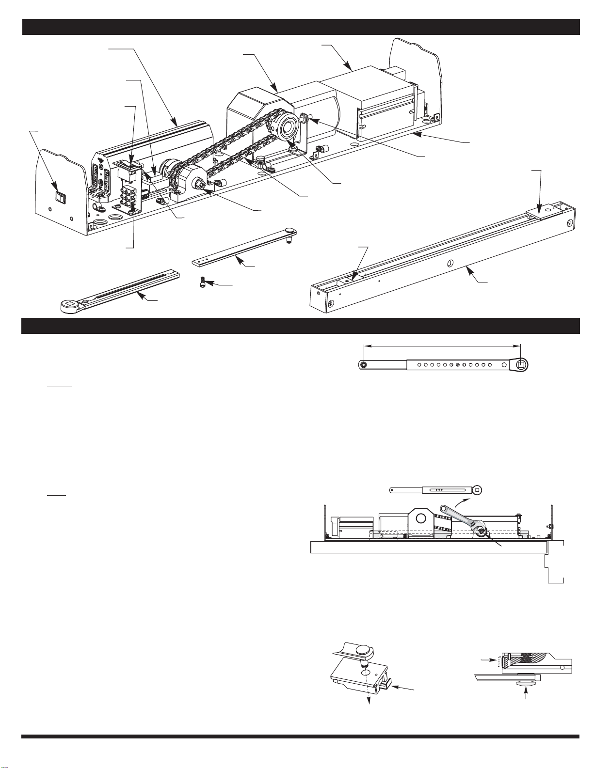
Adjust closing power of unit (See Fig.3) - Using a 1/8”
allen wrench, turn the power adjustment shaft clockwise
Adjust Hydraulic valves using a 1/8” hex wrench to
obtain proper door closing speeds. See following
Step 10:
Step 13:
Step 13:
OFF
Step 14:
Step 15:
Step 16:
Step 17:
Step 18:
Step 19:
Step 20:
Step 21:
Step 22:
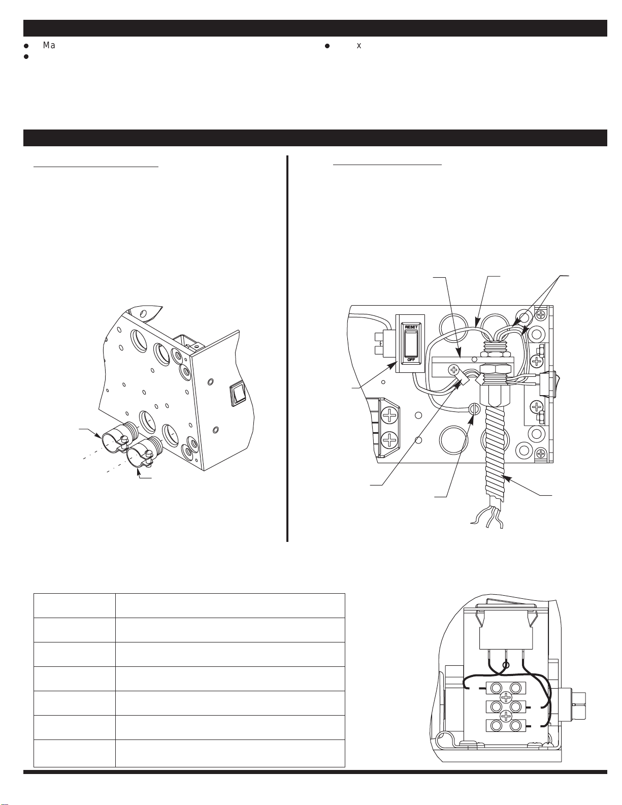
Turn power to unit on at the Unit Power Switch and turn the
Breaker Switch to “RESET”.
Using a short jumper cable, jump terminals 1 and 2, see Fig.
6 below, to activate unit. When door reaches 20 , switch
Breaker Switch to “ ” position cutting power to the unit.
Allow door to fully close (door may be manually pulled
closed).
Once door has fully closed, manually open door slightly and
insert a 1/8” allen wrench (provided with screw pack) into the
clutch assembly as shown below to create a small gap
between the two clutch components.
Manually close door and remove allen wrench from clutch
assembly.
Adjust Closing Ring Position (See Fig.8) - Loosen 8-32 set
screw located on Close Position Ring with 5/64” hex wrench
provided. Rotate Assembly until Closed Position Magnet
aligns with Reed Switch.
Adjust Open Ring Position - Loosen 8-32 set screw located
on Open Position Ring with 5/64” hex wrench provided.
Rotate Ring Assembly until Open Position Magnet is
approximately 180° from Closed Position Magnet.
Flip Breaker Switch to “RESET” to turn power on. Jump
terminals 1 and 2 (as shown in Step 13) to activate door.
Note open position of the door. Allow door to close.
Loosen and readjust Open Position Ring as necessary to
obtain desired door open position. Tighten set screw.
Make all connections necessary for any accessories to the
4-position Accessory Terminal (see Pages 6 - 8).
Make necessary adjustments to inverter (see Page 6).
Replace cover and cover screws.
°
Installation Sequence Continued
Power Adjustment
1/8"
Hex
Key
Increase
Power
Decrease
Power
80-9357-0110-020 Rev. A
4
Closing Cycle – Make adjustments, as necessary, to the Sweep
Speed "S" valve and Latch Speed "L" valve. See Fig. 4 below for
location of valves.Turn valves clockwise to reduce speed, counter
clockwise to increase speed.
1/8"
Hex
Key
Slower
Closing
Faster
Closing Closing Cycle
Closed
10°
L
a
t
c
h
R
a
n
g
e
S
w
e
e
p
R
a
n
g
e
Opening Cycle – Adjust Backcheck, "B" valve, as necessary, for
hydraulic resistance to door opening in the backcheck range. See
illustrationinFig.4atbottomofthispageforlocationofvalve.
1/8"
Hex
Key
Increase
Cushion
Decrease
Cushion
Opening Cycle
B
a
c
k
c
h
e
c
k
O
p
e
n
i
n
g
NOTE:ToomuchBackcheck,"B"valve,canaffect heoperation
of the units pump, preventing units from fully opening the
door. This valve may require fine tuning after all other
adjustmentshavebeenmade.
t
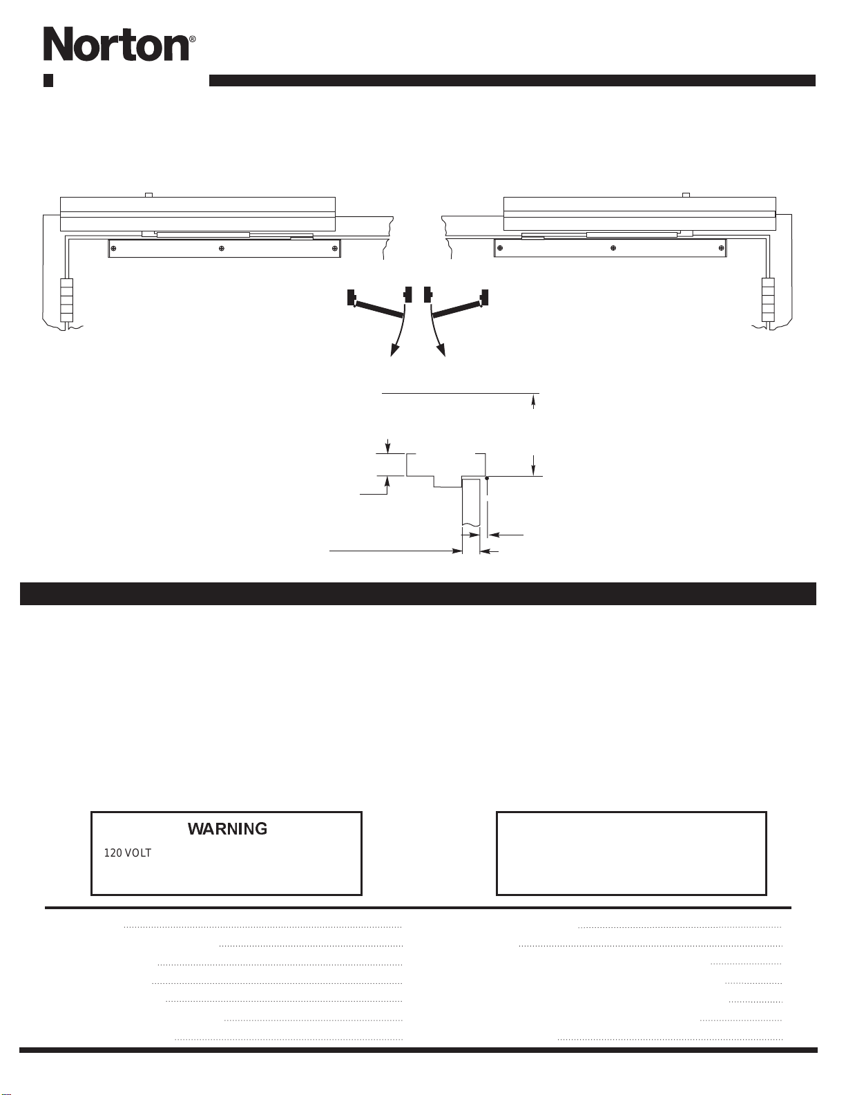
Note: A.D.A. requires that from an open position of
70°, the door will take at least 3 seconds to move to
a point 3”(75mm) from the latched position
measured at the leading edge of the door.
Step 11:
,
Make wiring connections using Wiring Instructions
on Page 5.
Step 12:Turn on facility’s main circuit breaker.
Figure 3
Sweep Valve
Latch Valve
Backcheck
Valve
Figure 4
Breaker
Switch
Unit Power Switch
Figure 5
1
2
3
4
1
2
3
4
Figure 6
1/8” Allen Wrench
Clutch Assembly
Figure 7
Reed Switch
Closing Position
Magnet
Closing Position
Adjustment
Opening Position
Magnet
Opening Position
Adjustment
Figure 8