Cristec Voltage Guard-70 User manual

Voltage Guard –70
The best solution to protect your battery
against :
Deep discharge
Overvoltage
Overload
Presentation
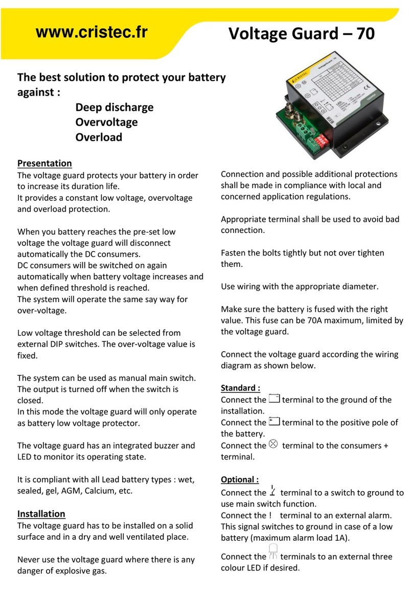
The voltage guard protects your battery in order
to increase its duration life.
It provides a constant low voltage, overvoltage
and overload protection.
When you battery reaches the pre-set low
voltage the voltage guard will disconnect
automatically the DC consumers.
DC consumers will be switched on again
automatically when battery voltage increases and
when defined threshold is reached.
The system will operate the same say way for
over-voltage.
Low voltage threshold can be selected from
external DIP switches. The over-voltage value is
fixed.
The system can be used as manual main switch.
The output is turned off when the switch is
closed.
In this mode the voltage guard will only operate
as battery low voltage protector.
The voltage guard has an integrated buzzer and
LED to monitor its operating state.
It is compliant with all Lead battery types : wet,
sealed, gel, AGM, Calcium, etc.
Installation
The voltage guard has to be installed on a solid
surface and in a dry and well ventilated place.
Never use the voltage guard where there is any
danger of explosive gas.
Connection and possible additional protections
shall be made in compliance with local and
concerned application regulations.
Appropriate terminal shall be used to avoid bad
connection.
Fasten the bolts tightly but not over tighten
them.
Use wiring with the appropriate diameter.
Make sure the battery is fused with the right
value. This fuse can be 70A maximum, limited by
the voltage guard.
Connect the voltage guard according the wiring
diagram as shown below.
Standard :
Connect the terminal to the ground of the
installation.
Connect the terminal to the positive pole of
the battery.
Connect the terminal to the consumers +
terminal.
Optional :
Connect the terminal to a switch to ground to
use main switch function.
Connect the ! terminal to an external alarm.
This signal switches to ground in case of a low
battery (maximum alarm load 1A).
Connect the terminals to an external three
colour LED if desired.
www.cristec.fr

Low voltage cut-off setting
The low voltage setting can be adjusted by the
dip switches according to the table below. The
voltage guard is permanently switched on when
DIP switches 1, 2 and 3 are on. In this case the
low voltage protection is disabled. The voltage
guard works only between 8VDC and 31VDC. Use
DIP switch 4 to enable or disable the internal
buzzer.
Power up
When the power is supplied to the voltage guard
an internal self-test is done. At this moment the
voltage guard determines the nominal system
voltage. In this situation the status LED will flash
once red-green and a beep can be heard.
At a power up voltage below 16V, the voltage
guard sets itself to 12V system voltage. If the
power up voltage is higher than 16V, the voltage
guard sets itself to 24V system voltage.
Using the voltage guard as a main switch
If a panel switch is connected according to the
drawing, the main switch function can be used.
The output is turned off when the switch is
closed. The status LED is off and flashes four
times a minute. The normal voltage guard
function is activated when the switch is opened.
Normally in this case the status led is lid green
and the output is switched on. Depending on the
battery voltage the led status can be different.
Without using the switch input, the voltage guard
will just function as a low voltage protection for
your battery.
Explanation status LED
Green : the battery voltage is ok. Output is
switched on.
Green blinking : flashing four times per minute,
optional panel switch is closed and the
consumers are switched off.
Orange : the battery voltage is lower than the set
prealarm.
Red blinking : Output is switched off because of
high or low voltage or overload.
Buzzer
The internal buzzer sounds by variable intervals
before reaching the shut off point. The interval
between the sounds will be shorter with every
repetition. Pauses between alarm pulses: 600s -
300 s - 150s - 75s - 38s - 19s - 9s.
Technical specifications
Rated current (constant) : 70 A
Max current (10s @ 20C°) : 140 A
Voltage : 12 and 24 VDC
Input voltage range : 8 - 31 VDC
Consumption : > 2mA (LED Off)
Presentation : Plastic housing with external
fixings –IP51
Connection : on threaded roads
Dimensions (l x h x e) : 100 x 89.2 x 43 mm
Weight : 0.21 Kg
Operating temperature : from -10°C to +60°C
Storage temperature : from -20°C to +85°C
12V low voltage adjustment : 9 - 12 VDC
12V overvoltage threshold : 15.5 VDC
24V Low voltage adjustment : 18 - 24 VDC
24V overvoltage threshold : 31 VDC

Voltage guard - 70
La solution pour protéger votre parc batteries contre :
les décharges profondes
les surtensions
les surcharges
Présentation :
Le voltage guard a pour fonction de protéger
votre parc batteries et donc d’optimiser sa durée
de vie.
Il assure une surveillance permanente en sous-
tension, en sur-tension et en surcharge.
Lorsque votre parc batteries devient trop faible, le
voltage guard déclenche automatiquement le
délestage des consommateurs. Le redémarrage
est automatique dès lors que la tension augmente
et atteint le seuil limite.
Le principe de fonctionnement est identique en
sur-tension.
Le choix du seuil requis en sous-tension s’effectue
via quatre micro-interrupteurs, accessibles de
l’extérieur.
Le seuil en sur-tension est fixe.
Ce dispositif de surveillance dispose par ailleurs
d’une commande ON/OFF externe optionnelle qui
permet de déconnecter manuellement les
utilisateurs. Dans ce mode d’utilisation, le voltage
guard surveille uniquement les sous-tensions.
Une alarme sonore est intégrée et une LED
tricolore permet de contrôler l’état du voltage
guard.
Il est compatible avec toutes les batteries de type
Plomb : ouvert, étanche, gel, AGM, Calcium, etc.
Installation
Le voltage guard devra être installé dans un
environnement sec et bien ventilé, idéalement
sur une surface plane et rigide.
Il est fortement déconseillé de l’utiliser en cas de
risque de dégagement gazeux.
Les connexions et l’ajout éventuel de protections
se feront en fonction des normes applicables à
l’installation concernée.
Utiliser des cosses appropriées afin de sécuriser la
connexion.
Serrer les écrous et veiller à dimensionner le
diamètre de câble correctement.
S’assurer que la batterie est protégée par un
fusible de calibre adapté ; 70A max limité par le
voltage guard.
Le voltage guard est à câbler comme suit :
Montage standard :
Relier la borne à la masse de l’installation.
Relier la tige filetée à la borne positive de la
batterie.
Relier la tige filetée au positif des
consommateurs CC.
Montage optionnel :
Relier la borne à un interrupteur pour une
commande ON/OFF.
Relier la borne ! à un dispositif d’alarme externe.
Ce signal commute à la terre en cas de tension
batterie basse (charge maximum 1A d'alarme).
Relier les bornes à la LED tricolore si souhaité.
www.cristec.fr

Paramétrage coupure en sous-tension
Le paramétrage de coupure en sous-tension se
fait via des micro-interrupteurs; voir tableau ci-
dessous. Le voltage guard est en mode ON
permanent quand les micro-interrupteurs 1, 2
et 3 sont ON. Dans ce cas, la protection en
tension basse est inhibée. Le voltage guard
fonctionne entre 8 et 31VCC.
Utiliser le micro-interrupteur 4 pour actionner
ou non le buzzer.
1 2 3 4 12V 24V 12V 24V 12V 24V
0 0 0 - 9 18 9,5 19 10,5 21
1 0 0 - 9,5 19 10 20 11 22
0 1 0 - 10 20 10,5 21 11,5 23
1 1 0 - 10,5 21 11 22 12 24
0 0 1 - 11 22 11,5 23 12,5 25
1 0 1 - 11,5 23 12 24 13 26
0 1 1 - 12 24 12,5 25 13,5 27
1 1 1 - - - - - - -
- - - 0
- - - 1
Buzzer OFF
Réglage des micro-interrupteurs
Position
Tension basse
Coupure
Pré-alarm
Tension basse
Redémarrage
Buzzer ON
Mise sous tension
Lors de sa mise sous tension, le voltage guard
effectue un auto-test. C’est dans cette phase qu’il
détermine la tension de référence de
l’installation. La LED clignote une fois rouge-vert
et un bip est émis par le buzzer.
Si à la mise sous tension la tension détectée est
inférieure à 16V alors le voltage guard se
configure automatiquement en mode 12V. Pour
toute tension supérieure à 16V, il se configure en
24V.
Actionner le voltage guard en coupe circuit
Si un commutateur optionnel est câblé comme sur
le schéma, la fonction coupe circuit manuelle est
disponible. La sortie est coupée lorsque le contact
est fermé. La LED clignote alors 4 fois par minute.
Le fonctionnement normal du voltage guard est
activé lorsque le contact est ouvert, la LED est
allumée en vert et la sortie est ON. A noter que la
couleur de la LED peut dépendre de la tension de
la batterie.
Si l’entrée commutateur n’est pas utilisée, le
voltage guard assurera une protection en tension
batterie basse.
Etat de la LED
Verte : la tension de la batterie est bonne.
La sortie est active (consommateurs présents).
Verte clignotante : 4 fois par minute, le contact
est fermé et les consommateurs 12V sont coupés.
Orange : la tension de la batterie a atteint le seuil
prédéfini.
Rouge clignotante : la sortie est coupée
(consommateurs délestés) : surcharge, sous-
tension ou sur-tension détectée.
Buzzer
L’alarme sonore interne va retentir par
intermittence avant la coupure. L’intervalle entre
chaque son va diminuer progressivement : 600s -
300 s - 150s - 75s - 38s - 19s - 9s.
Caractéristiques techniques
Courant nominal (permanent) : 70 A
Courant de pointe (10s @ 20C°) : 140 A
Tension de fonctionnement : 12 et 24 VCC
Plage de tension d’entrée : 8 - 31 VCC
Consommation : > 2mA (led éteinte)
Présentation : Boîtier plastique avec fixation
externes –IP51
Connexion : sur tiges filetées
Dimensions (l x h x e) : 100 x 89.2 x 43 mm
Poids : 0,21 kG
Température de fonctionnement : de -10°C à +60°C
Température de stockage : de -20°C à +85°C
Ajustage tension batterie basse 12V : 9 - 12 VCC
Seuil de sur-tension 12V : 15,5 VCC
Ajustage tension batterie basse 24V : 18 - 24 VCC
Seuil de sur-tension 24V : 31 VCC
Table of contents
Languages:
Other Cristec Protection Device manuals
