Cromemco BIART User manual

r---
~
Cromemco
BIART
Communication
Processor
Instruction Manual
_....--- .. November 1984
CROMEMCO, Inc.
P.O. Box 7400
280 Bernardo Avenue
Mountain View, CA 94039
023-20H
Rev. A
Copyright ©1984
CROMEMCO, Inc.
All Rights R'~

This manual was produced using a Cromemco System Three computer
running under the Cromemco Cromix Operating System. The text was
edited with the Cromemco Cromix Screen Editor. The edited text
was proofread by the Cromemco SpellMaster Program and formatted
by the Cromemco Word Processing System Formatter II.
\ Camera-ready copy was printed on a Cromemco 3355B printer.
The following are registered trademarks of Cromemco, Inc.
C-Net®
Cromemco ®
Cromix ®
FontMaster®
SlideMaster®
SpellMaster®
System Zero®
System Two®
System Three®
WriteMaster®
The following are trademarks of Cromemco, Inc.
C-IO ™
CalcMaster ™
DiskMaster ™
Maximizer ™TM
System One
TeleMaster ™
-
-'--"''''''
~
-~-

r---
"'--'..,
TABLE OF CONTENTS
TECHNICAL SPECIFICATIONS
INTRODUCTION
Chapter 1: SET UP AND INSTALLATION
BIART ROM
BIART Base I/O Address
Connectors and Cables
Reset Connector
Connector J2
Connectors Jl and J3
Connector 4
Chapter 2: PROGRAMMING INFORMATION
Introduction
BIART Reset
BIART Interrupts
Internal BIART Interrupts
Host Interrupts
BIART, Host Communications
Host Commands to the BIART
BIART Status to the Host
Host Data to the BIART
BIART Data to the Host
LIST OF APPENDICES
Appendix A: BIART Register Descriptions
Appendix B: RS-232C, RS-422, and RS-423 Interfaces
Appendix C: Six-Bit Transcode
Appendix D: ASCII Character Code
Appendix E: EBCDIC Character' Code
Appendix F: Parts List
SCHEMATIC
INDEX
LIMITED WARRANTY iii
1
3
5
5
6
7
8
9
9
11
11
13
14
14
15
15
15
16
16
17
19
37
41
43
45
47
51
55

Figure 1-1:
Figure 1-2:
Figure 1-3:
Figure 1-4:
c
LIST OF ILLUSTRATIONS
The BIART Board
BIART Switch Settings
Installing the Priority Cable
BIARTRS-232C Interface
4
8
8
9
-.----'"
Figure B-1: RS-232C Interface Wiring
Figure B-2: RS-422 Interface Wiring
Figure B-3: RS-423 Interface Wiring
38
38
39
LIST OF TABLES
.Table
1-1:
Host, BIARTCommunication Ports 6
Table 1-2 :
BIARTConnectors and Pin-Outs 7
~
Table
2-1:
BIARTRegister Summary 12
Table 2-2:
Registers after BIARTReset 14
Table
B-1:
Serial Interface Specifications 37
iv

/'--.
BIART TECHNICAL SPECIFICATIONS
Processor: Z80B, 5.5 MHz clock
Memory: Software selectable configurations:
- 64 Kbytes DRAM,or
- 16 Kbytes ROM, 32 Kbytes DRAM
Parallel Channels: One 8-bit input channel; one Centronics printer
compatible 8-bit output channel
Parallel Interface: LSTTL levels
Serial Channels: 2 independent channels
Serial Protocols: - Asynchronous Byte
- Synchronous Byte (IBM BiSync)
- Synchronous Bit (SDLC/HDLC)
.r____.
.r---··o
Serial Bit Coding:
Serial Interface:
Channel Data Rates:
Character Length:
Error Detection:
Interrupts:
LSI Device Types:
- NRZ
- NRZI
- FMO(bi-phase space)
- FMl (bi-phase mark)
RS-232C, RS-422, and RS-423 (with circuits TxD,
RxD, TxC, RxC, CTS, RTS, OCD, and DTR)
Asynchronous, 30.5 to 19,200 baud with x16 clock
multiplier, baud rate varied by dividing a local,
crystal controlled 5.5 MHz clock by a programmable
16-bit scale factor; synchronous, 0 to 1 lVIbits/sec
with xl clock multiplier
Transmitter, 1 to 8 bits; receiver, 5 to 8 bits
Parity, CRC-16 or CRC-CCITT generation and
checking, receiver framing and overrun, transmitter
underrun, break generation and detection
Software controlled, vectored maskable interrupts
from the BIART directed to the host processor;
vectored maskable interrupts from Z-SCC channel,
the parallel port, and from host I/O with the BIART
registers directed to the BIART Z80B
1 - Z80B CPU (Central Processing Unit)
1 - Z8530A SCC (Serial Communications Controller)
8 - 4164 64Kx1 bit DRAM(dynamic RAM)
1 - 27128 16Kx8 bit ROM(user supplied)
1 - Custom CMOSCircuit
v

Host Interface:
S-100/IEEE-696 Power:
Operating Environment:
Two bi-directional S-100/IEEE-696 bus I/O ports;
S-100/IEEE-696 maskable vectored interrupts
+ 8 VOC @1.5 A
+18 VOC @250 mA
-18 VOC @250 mA
o - 55 degrees Celsius
vi
.._/~
'--..-/

r---"
Cromemco BlART Communication Processor Instruction Manual
Introduction
INTRODUCTION
This manual provides installation, operating, and programming instructions for
Cromemco's BIART communications processor board. The BIART board is a
second generation, co-processing subsystem which interfaces two serial
channels and a bi-directional parallel port to a host S-100/IEEE-696 bus. A
typical BlART application might consist of interfacing two computer terminals
or modems and a Centronics-compatible parallel printer to the host system.
Unlike earlier serial interface boards, which merely formatted and exchanged
individual data characters, the BlART features a sophisticated dual channel
Z-SCC serial communications circuit, plus an independent Z80B processor with
6"4 'Xbytes of memory. Because the BIART performs all protocol and error
detection/recovery functions, buffers large amounts of serial data, and passes
only pre-processed data over the host bus, the host CPU is relieved of many
I/O functions, and system throughput is dramatically increased.
The BIART is a versatile serial subsystem, compatible with both Z80 Cromix
version 11.27 and higher, and 68000 Cromix version 20.63 and higher. Under
program control, it can switch its internal memory configuration from 16 Kbytes
of ROMand 32 Kbytes of RAMto a full 64 Kbytes of RAM. Thus the board can
include a ROMbootstrap program which loads an application program, and then
switches to 64 Kbytes of RAM for maximum buffer space. The two serial
channel scan 0perate independently of one another in asy nc hron ou s,
byte-synchronous (IBM BiSync), or bit-synChronous (SDLC/HDLC) mode, and
each channel can encode and decode NRZ, NRZI, FMO, or FlVIl data.
Chapter 1 describes how to install the BIART board in an S-100 bus system.
Chapter topics include cables, switch settings, and connector pin assignments.
Chapter 2 presents BIART programming information. This chapter assumes the
reader is familiar with programming in general, and with Z80 Assembly Language
in particular (see Reference 1). Most of the information in this chapter relates
to several BIART registers through which the Z80B processor manages all board
functions. Several of these registers are mapped to access internal Z-SCC
registers; detailed programming information for this device is contained in
Reference 2 below.
Positive logic is assumed throughout the manual. That is, logic 0 is associated
with a more negative voltage (near 0 VOC), and logic 1 with a more positive
voltage (near +4 VOC). Reset means logic 0, and set means logic 1, as these
terms apply to bit states. The *notation appearing after a signal name means
that the signal is active in the logic 0 state (e.g., signal RESET* is active when
at logic 0 and inactive when at logic 1).
Reference 1
Reference 2
Zilog, Inc., Z80 Assembly Lan~ua~e Pro~ammin~ Manual, 1977
,Zilog, Inc., Z8030/Z8530 Seria I C&mmunication G.ontroller
Technical Manual, April 1982
1

renUl1W uont)T1J~SUI JoSsat:>OJd UOnl1t)!UnWW0:J .LlIVHI ot)wawoJ:J

~
~--
./~."...
Cromemco BIARTCommunication Processor Instruction Manual
1. 8et Up and Installation
Chapter 1
SET UP AND INSTALLATION
The BIART board is set up by inserting a ROMdevice in socket ICll, cutting
a jumper strap (B) if the ROMhas an access time of 150 n8ec or less, and setting
switch 8W-1 to select an 8-100 base port address. After the board is set up,
insert it in an empty 8-100 bus slot with power off. Connect cables between
the serial DCE equipment, the parallel printer, and the BIART, and place the
BIART in the 8-100 buS"interrupt priority chain. All of these steps are
explained, in order, in the following sections.
3

J2
Interrupt
Priority
J1
Serial
Channel A
J3
Serial
Channel B
BCut Jumper
For 150 nsec
ROM
Reset J4
Parallel
Figure 1-1: THE BIART BOARD

Cromemco BIART Communication Processor Instruction Manual
1. Set Up and Installation
BIART ROM
Whenever the BIART board is reset (many events can reset the board -- see the
section, "BIART RESET" in chapter 2).
1. The BIART memory configuration is switched to 16 Kbytes of ROMfrom
OOOOh- 3FFFh, and 32 Kbytes of RAM from 4000h - BFFFh, and
2. The Z80B processor is reset. This means, among other things, that it starts
executing whatever program code starts at memory address OOOOh.
Thus, the ROMfirmware must be in place to start up the BIART board after a
reset.
The BIART board supports the 16K x 8-bit 27128 ROM, or any pin compatible
equivalent. The access speed of the installed ROMis 450 nanoseconds. If you
want to use a faster ROM(150 nSec or less), cut jumper "B" between IC19 and
IC20 (see figure 1-1).
BIART BASE I/O ADDRESS
The host processor and the BIARTcommunicate through two bi-directional S-100
bus I/O ports. The communication can be either polled or interrupt-driven.
BIART switch SW-1 defines the base I/O port number, Bbase, which the host
SW-1
A7 -1-~u
0
A6 -1•.. -
0
••• ~G)A5 -1.w
0206
A4 -1_.t>-
oBIART -
A3 -1...~
0
A2 --1•••m0
(Base
AddressCEh)
A1 -1•
~0
Reset Disable
~CD
Enable
SW-1
A7 -1~:<:~-
0
A6 -1· :'1\,)
0@
A5 -1••
w
0-:;:
·1
r.;
A4 -1••. :b
0BIART
A3 --1_ ..:v.
0
A2 -1_.-.01
0
(Base
AddressBEh)
A1 -1•.. :~
0
Reset Disable
l:iotIoo
Enable
SW-1
A7 -1-zo
0
A6 -1•.... -
0@
A5 -1:_0\)
0I
(/'
:"' __:'w .-
-f-
A4- 1
·_.:.::..
0
A3 -1••. _.:(J'I
0BIART
A2 -1•... 0'>
0
(Base
Address
AEh)
A1 -1-...::~
0
Reset Disable
L:.MJoo
Enable
SW-1
A7 -1•• z--2_
0
A6 -1-~
0@
A5 -1, :-t'w
0
A4- 1
....
b
0BIART I
';-'2
-
A3 --1" __ .<J'
0
A2 -1•••
m
0(Base
Address9Eh)
A1 -1••......
0
Reset Disable
I
~:c Enable
Figure 1-2: BIART SWITCH SETTINGS
5

Cromemco BIARTCommunication Processor Instruction Manual
1. Set Up and Installation
uses to access these two ports. Table 1-1 shows the port number assignments.
Notice that port addresses may be changed relative to the host processor with
switch SW-I, but are fixed relative to the BIART's Z80B processor.
Table 1-1: HOST, BIART COMMUNICATION PORTS
Register Name HostBIART
Commands from Host
OUT Bbase+OOh-) IN
OOh
Status to Host IN
Bbase+OOh <- OUT OOh
Data from Host OUT Bbase+01h-) IN
01h
Data to Host IN
Bbase+O1h <- OUT 01h
Figure 1-2 shows the recommended switch settings for each of the four BIART
boards supported by the Cromix Operating System. With the settings shown for
BIART #1, Bbase =CBh. Thus the host processor addresses output port CFh
to send a data byte to register Data From Host, and the BIART's Z80B
processor reads the same byte from input port 01h.
CONNECTORS AND CABLES
There are five BIART connectors, Reset and J1 through J 4, located along the
top of the board (see figure 1-1). The Reset connector resets the BIARTboard,
J2 connects the BIART in the S-100 interrupt priority chain, J1 connects to
serial channel A, .J3 connects to serial channel B, and J 4 connects to a
Centronics-style parallel printer or other parallel I/O device.
With system power off, route three 25-conductor ribbon cable assemblies
(Cromemco part number 519-0017, 62 cm long, or 519-0008,110 cm long) through
the computer system housing for BIART connectors J1, J3, and J4 (use fewer
cables if not all connectors are used). Secure the DB-25S socket end of each
cable to the connector cutouts on the system rear panel. Clearly mark each
ribbon cable with the connector number from the rear panel. Route the cables
so that the 26-pin female connectors comfortably reach connectors J1, J3, and
J 4 when the BIART board is installed. Install the BIART board in an empty
S-100 bus slot. Do not turn on system power until all cabling is installed.
Table 1-2 defines the pin-outs of all BIART connectors. A dashed table entry
(---) denotes no connection (a floating pin). GROUNDentries denote a direct
connection to S-100 bus GROUNDat 0 VOC.
6
--.--/

~
Cromemco BIART Communication Processor Instruction Manual
1. Set Up and Installation
Table 1-2: BIART CONNECTORS AND PIN-oUTS
CONNECTOR
PIN Jl J3
J4.
<1>
--- ---
---
.<2> RxD-ARxD-BINPUT STROBE*
. '-
't <3> TxD-A
TxD-B
+5 VDC
<4> RTS-ARTS- BBIT 6 IN
<5> CTS-ACTS-BBIT 4 IN
<6> DCD-AOCD- B
BIT 2 IN
<7> GROUNDGROUNDBIT 0 IN
<8> DCD-AOCD- BDISABLE*
<9> TxC-A*
TxC-B*OUTPUT STROBE*
<10> --- ---
BIT 6 OUT
<11> TxD-A2*
TxD-B2*
BIT 4 OUT
<12> DCD-A *DCD-B*
BIT 2 OUT
<13> CTS- A*
CTS-B*
BIT 0 OUT
<14> TxD-A2
TxD-B2GROUND
<15> TxC-A
TxC-BSENSE*
<16> RxD-A*RxD- B*
BIT 7 IN
<17> RxC-A
RxC-BBIT 5 IN
<18> RxC- A*
RxC-B*
BIT 3 IN
<19> RTS-A2
RTS- B2BIT 1 IN
<20> DTR-ADTR- BNMI*
<21> --- ---
WAIT*
<22> --- ---
BIT 7 OUT
<23> DTR-A2DTR-B2BIT 5 OUT
<24> DTR-A2*
DTR-B2*
BIT 3 OUT
<25> RTS-A2*
RTS-B2*
BIT lOUT
.~
~
~ 1
\} '"
~tt
t"t
i1,(J '):
"
\\ 1,
'~':l.
~~,..
~'1 ';!
~
N)~
0- "
N~
~J
~
CONNECTOR
PIN RESET
J2
<1>
RESET*
PRIORITY IN*
<2> GROUND
PRIORITY OUT*
~~-.~
RESET CONNECTOR
The pins of this connector can be wired to a normally open pushbutton switch,
or pin RESET* can be wired to any output capable of sinking 2 mA to ground
(one bit of an output port, for example). Forcing pin RESET* to logic 0 resets
the entire BIART board.
7

Cromemco BIARTCommunication Processor Instruction Manual
1. Set Up and Installation
CONNECTOR J2
Connecting the priority interrupt cable (part number 519-0029) to J2 on the
BIART board determines the order in which the host processor services BIART
interrupt requests when they conflict with those from other boards in the
system.
Attach the first connector on the priority interrupt cable to J1 on the
64FOC/16FOC board by aligning the blue dot on the connector with the blue dot
on the plug (see figure 1-2). Aligning the yellow dots on the remaining plugs
and connectors, attach the second connector to the next highest priority board,
the third connector to the next highest, and so on. The suggested order of board
priorities is: 64FOC/16FOC, STOC, OCTART, TU-ART, lOP, BlART, MAXIMIZER,
GPIB, CTI, PRI, and SCC. The order of the boards between the 64FOC/16FOC
and the SCC is not critical, as long as no boards or connectors are skipped.
Any unused connectors must be at the end of the cable farthest from the
64FOC/16FOC.
If your priority connectors are not color coded, install the cable so that the
OUT pin of the higher priority board is linked to the IN pin of the next highest
board (the IN pin is on the right on all boards except 64FOC/16FOC, STOC, and
CT!). The IN pin of the highest priority board (the 64FOC/16FOC) is not
connected, nor is the OUT pin of the lowest priority board (the last board in
the chain).
To Next Priority Board
STDC
Yellow Dot
Figure 1-3: INSTALLING THE PRIORITY CABLE
8

Cromemco BIARTCommunication Processor Instruction Manual
1. Set Up and Installation
CONNECTORS Jl AND J3
Connectors J1 and J3 interface serial (RS-232C, RS-422 or RS-423) OCE
equipment to the BIART board. Connector J1 attaches to serial channel A, and
J3 attaches to serial channel B. Figure 1-3 shows the relationships among
incoming and outgoing voltage levels and logic states.
Logic 1
Marking,
Off: -5.6V
MC3488
BIART
TTL
Levels
Logic 0
Spacing,
On: +5.6V
Logic 1
Marking,
Off:<-5VDC
Logic 0
Spacing,
On:>+5VDC
DCE
RS -232C
Levels
.-----
Figure 1-4: BIART RS-232C INTERFACE
Choose two ribbon cables attached to the system housing rear panel (installed
above), align the red cable stripe of each cable with the BIART board legend
arrowheads, and attach the 26-pin female connectors to BIART connectors J2
and J3. Attach the terminals or other DCE equipment at the system back panel
DB-25S sockets. The BIART, supports the RS-232C interface without
modification. For the RS-422 or RS-423 interface, see appendix B.
CONNECTOR J4
Connector J4 interfaces either a Centronics-style parallel printer, or a general
purpose TTL level parallel I/O device to the BIART board. Attach the 26-pin
female connector to BIART connector J 4, aligning the red cable stripe with the
board legend arrowhead. Attach the parallel printer or other parallel I/O device
at the system back panel DB-25S socket •
9

01
pmuuV\j uon<>n.qsuI Jossa<>OJd Uo!w<>!unwwoo J,lIVIH o<>llIawoJO

~
Cromemco BIARTCommunication Processor Instruction Manual
2. Programming Information
Chapter 2
PROORAMMING INFORMATION
INTRODUCTION
The BIART is a co-processing I/O management subsystem for the 8-100 bus host
processor. Application software for this architecture is normally structured
as follows:
/-.
1. The host to BIART link is made as short, fast, and simple as possible. This
means the routine running in host memory should view the BIART as a
simple data source or sink, with a minimum amount of status and command
information required to carry out a data exchange. Normally, only
pre-processed data should travel on the 8-100 bus on a vectored
interrupt-driven basis.
"...--.~,
2. The routine running in BIART exchang"es comma~ds, status, and data with
the host processor. To off-load the host processor, the BIART routine
should also assume responsibility for connecting and disconnecting serial
links, managing serial protocols, formatting or processing the serial data
(such as data encry ption and decry ption), managing the parallel printer,
monitoring data integrity, and attempting all possible error recovery
procedures for the host processor.
The BIART program store is 16 Kbytes of ROM from OOOOh- 3FFFh, and 32
Kbytes of RAM from 4000h - BFFFh, immediately after a BIART reset (see the
next section). Under program control, the memory configuration can later be
switched to 64 Kbytes (OOOOh- FFFFh).
The BIART Z80B processor manages all board functions through several I/O
mapped registers, which are listed in table 2-1. The BIART Z80B accesses all
but four of these registers by executing either a single input instruction (e.g.,
IN A, (51h) to read register Channel B Receive Data), or a single output
instruction (e.g., OUT A, (51h) to write to register Channel B Transmit Data)
to the target register's port address. The port number and direction (from the
BIART Z80B's point of view) for each register is shown in the table. Four of
the registers (Channel A Status, Channel B Status, Channel A Commands,
Channel B Commands), require either one or two I/O instructions, depending
upon which internal Z-SCC register is accessed. Detailed descriptions for
these registers appear in appendix A.
11

Cromemco BIART Communication Processor Instruction Manual
2. Programming Information
.~/
Table 2-1: BIART REGISTER SUMMARY
BIART
HOST REG ISTER
PORT PORT FUNCTION
IN
OOhOUT Bbase+OOhCommands from Host
OUT OOh INBbase+OOh Status to Host
IN 01h OUT Bbase +0Ih
Data from Host
OUT 01h INBbase+O Ih Data to Host
IN
02h --- BIART Flags
OUT 02h --- BIART Control
OUT 03h --- Interrupt Vector To Host
IN
lXh --- Parallel Input
OUT IX!) --- ParaUel Output
OUT 4Xh
--- Configure Memory
IN
50h --- Channel B Status
OUT 5Oh --- Channel B Command
IN 51h --- Channel B Receive Data
OUT 5lh --- Channel B Transmit Data
I
,_.-/
IN 52h --- Channel A Status
OUT 52h --- Channel A Command
IN 53h --- Channel A Receive Data
OUT 53h --- Channel A Transmit Data
The last eight BIART registers are mapped to access the internal Z-SCC
registers which manage serial channels A and B. In this group, the command
and status registers each access multiple Z-SCC registers. Through register
Channel B Command, for example, the BIART Z80B can write to 16 channel
B internal registers, WRO through WRl5. See Reference 2 for detailed Z-SCC
programming information.
The next two registers in the table pass 8-bit parallel data to and from BIART
connector J4. Bit DO of the next register, Configure Memory, controls the
BIART on-board memory configuration.
The next four registers are accessible to both the host processor and the BIART
Z80B processor. They are used to exchange commands, status, and data between
the host and BIART processors. Notice that a host input port is a BIART output
port, and vice versa. The host (S-100 bus) port address of these four registers
can be changed with BIART switch SW-l (see Section 1.2), but to the BIART's
Z80B, the port numbers are fixed.
12

~
Cromemco BIARTCommunication Processor Instruction Manual
2. Programming Information
The first three registers in the table are used for monitoring BIART flags (for
example, to determine if a command byte from the host processor is available),
to control the BIART interrupt circuitry, and to issue interrupt vectors to the
host processor, respectively.
BIART RESET
Several events can reset the BlART board:
1. Applying power to the BlART board. BIART Power On Clear (POC)
circuitry generates a momentary active low pulse on line RESET* (IC14
pin 8) whenever S-100 bus lines 1 and 51 go from 0 VDC to +8 VOC.
2. An S-100 bus reset. This occurs whenever S-100 bus line 75, pRESET*,
pulses active low. The reset condition persists as long as pRESET* is
held low.
~.
3. Forcing the RESET* pin of BIART connector Jl active low. This can be
done by either shorting pins RESET* and GROUNDof J1 with a normally
open pushbutton switch, or by driving pin RESET* of Jl active low with
any output capable of sinking 2 mA @+0.4 VDC or less. Pin RESET* must
go inactive high again to remove the reset condition.
~'"
4. A software reset. If BIART switch SW-1, section 8 is ON (see figure 1-1),.
then the host can reset the BlART board by sending the following six bytes
to register Commands From Host: 7Eh, 55h, OFh, 70h, 2Ah, and 7Eh.
These bytes cause a momentary reset condition. If this command sequence
is altered in any way, no BlART reset occurs. To disable the software
feature, set switch 8 of SW-1 OFF. Only DOthrough D6 are used. D7 is
not used for software reset.
All four of these events force line RESET* on the internal BlART control bus
to go active low. This event is called a BIART reset throughout this manual.
A BIART reset initializes the BIART board as follows:
1. The BlART memory configuration is unconditionally switched to 16 Kbytes
of RAMfrom OOOOh- 3FFFh, and 32 Kbytes of RAMfrom 4000h - BFFFh.
2. The BlART Z80B is reset. This means Z80B maskable interrupts are
disabled, the I-register is initialized to OOh,the R-register is initialized
to OOh,interrupt mode IMOis selected, and the Z80B automatically starts
executing program code at OOOOhas soon as the reset condition is removed.
3. Selected BlART register bits are forced either set (logic 1) or reset (logic
0), as shown in table 2-2. All other BIART register bits are unaffected.
13

Cromemco BIARTCommunication Processor Instruction Manual
2. Programming Information
Table 2-2: REGISTERS AFTER BIART RESET
Bit #OUT 4Xh
OUT 50hIN 52hOUT 52h
D7
--- 1
1
---
D6 --- 0
0
---
D5 --- 0
---
---
D4 --- 0
---
---
D3 --- 0
---
---
D2 --- 0---0
D1 --- 1
1
---
DO 1RESET*00
BIART INTERRUPTS
For maximum system throughput, all I/O between the host and BlART, and
between the BlART and its peripherals, should be interrupt-driven. There are
two categories of BIART interrupts: internal BlART interrupts and host
interrupts. The following paragraphs discuss each category.
INTERNAL BIART INTERRUPTS
The BlART's Z80B processor can be interrupted by a variety of sources on the
board itself. The maskable interrupts issued by these sources, and directed to
the BlART's Z80B (in contrast to those directed to the host processor) are
collectively termed internal BIART interrupts. The internal BIARTinterrupt
sources, frpm highest to lowest interrupt priority, are:
1. Z-SCC interrupt requests. The Z-SCC can be programmed to issue
interrupt requests to the BlART Z80B in a variety of channel conditions,
and to supply a variable interrupt vector which pinpoints the channel and
interrupt condition within the channel when the BlART Z80B acknowledges
the request. These conditions include Tx Buffer Empty, Rx Character
Available, External or Status Conditions, and Special Receive Conditions.
Z-SCC interrupts have the highest internal BIARTinterrupt priority. See
Reference 2 for more information on Z-SCC interrupts.
.--/'
'-..-.-/
2. Parallel device interrupt requests. A parallel device attached to BIART
connector J4 can issue a maskable interrupt request to the BlART Z80B
by forcing pin 15, SENSE*, active low. When the Z80B acknowledges the
request, on-board circuitry automatically supplies interrupt vector .FAh
(F8h when host I/O and parallel device requests coincide) to the
processor, and removes the interrupt request. If the parallel device is
a printer, the interrupt request would normally signify that the printer
is ready to accept a new character, and the interrupt service routine would
send it one, if available. Parallel device interrupt requests have lower
priority than Z"SCC requests, but the same priority as host I/O requests.
If bit Enable Parallel Port Interrupt is reset, this feature is disabled.
(See BIART Control register.)
14
"--.--'"
Table of contents
Other Cromemco Computer Hardware manuals

Cromemco
Cromemco Multi-User BASIC User manual

Cromemco
Cromemco 32K Bytesaver User manual
Cromemco
Cromemco 64KZ User manual
Cromemco
Cromemco BYTESAVER User manual

Cromemco
Cromemco D+7A I/O User manual

Cromemco
Cromemco Dazzler User manual

Cromemco
Cromemco 299B User manual
Cromemco
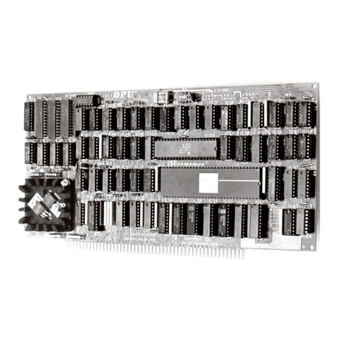
Cromemco Z80 User manual

Cromemco
Cromemco ZPU User manual
Popular Computer Hardware manuals by other brands
VIA Technologies
VIA Technologies AMOS-820 SKU Development guide
Linear Acoustic
Linear Acoustic LA-5300 Installation & user guide

SMART
SMART SRS-3 Installation and service manual
Thermalright
Thermalright Silver Arrow ITX-R instruction manual
Tektronix
Tektronix IPB220 Hardware installation and maintenance guide
Data Translation
Data Translation DT351 user manual
