Crommelins Cromtech 7000ie User manual

CROMTECH 7000ie
OPERATION MANUAL
INVERTER GENERATOR

1
WARRANTY TG7000IE
12 months / 300 hours (whichever comes rst)
Cromtech™ and Crommelins™ are a registered trademark of Crommelins
Machinery. Crommelins Machinery warrants their goods against defects
in materials and workmanship under normal use and service. The
warranty does not cover fair wear commensurate with the age of the
product, any damage caused by accident, abuse, misuse, neglect or
failure to observe proper operang instrucons or proper machinery
maintenance as described in the instrucon manual. It is the owner’s
responsibility to regularly maintain a product in accordance with the
owner’s manual and only use the equipment for its designed purpose.
Our goods come with guarantees that cannot be excluded under the
Australian Consumer Law. You are entled to a replacement or refund
for a major failure and for compensaon for any other reasonably
foreseeable loss or damage. You are also entled to have goods repaired
or replaced if the goods fail to be of acceptable quality and the failure
does not amount to a major failure.
CONSUMER ADVICE
Any claim under these warranes must be made in the warranty
period from the date of purchase of the product. There are over
185 naonal authorised service/repair agents available, visit
www.crommelins.com.au for their details and locaons. To make a
claim under the warranty, you must return the product (with proof of
purchase) to the closest warranty agent or to the place of purchase.
Where a failure does not amount to a major failure, Crommelins
Machinery is entled to choose between providing you with a repair,
replacement or refund. To obtain compensaon, you would need to
provide documentary evidence of the loss or damage suered, and
documentary evidence that such loss or damage was a reasonably
foreseeable consequence of a failure by Crommelins Machinery to
comply with a consumer guarantee under the Australian Consumer Law.
Crommelins Operaons Pty Ltd trading as Crommelins Machinery,
The Crommelin Group and Crommelins Australia.
Ph: 1300 650 659
PO Box 352, BENTLEY WA 6982
Email recepon@crommelins.com.au
www.crommelins.com.au
ABN 11 008 889 656
CONTENTS
INTRODUCTION ................................................................................. 3
SAFETY PRECAUTIONS...................................................................... 3
IMPORTANT ICONS ........................................................................... 3
SAFETY INFORMATION..................................................................... 4
Connecon to a Home Power Supply .........................................6
Safety Regulaons ....................................................................... 6
CONTROL FUNCTION ........................................................................ 8
TG7000ie Diagram ........................................................................ 8
Control Panel Diagram.................................................................. 9
Engine Switch..............................................................................10
Start Buon.................................................................................10
Recoil Starter...............................................................................10
ESC Throle Switch.....................................................................11
Digital Display Meter..................................................................12
Oil Warning Light ........................................................................15
Overload Indicator Light (Red)...................................................16
AC Pilot Light (Green) .................................................................16
Ground (Earth) Terminal.............................................................16
AC Circuit Breaker .......................................................................17
Folding Handle ............................................................................17
Maintenance Door......................................................................17
PRE-OPERATION...............................................................................18
Fuel...............................................................................................18
Add fuel ....................................................................................18
Engine Oil.....................................................................................18
Oil level .....................................................................................18
OPERATION.......................................................................................19
Starng The Engine.....................................................................19
Start BUTTON ...........................................................................19
APP Start – ANDROID...............................................................20
APP Start – APPLE.....................................................................21
Recoil Start................................................................................22
Stopping The Engine...................................................................23
Alternang Current (AC) Connecon ........................................24
32
INTRODUCTION
Thank you for purchasing this Cromtech generator.
We recommend that the operator read this manual
carefully before using this generator, and fully understand all
requirements and operang procedures.
SAFETY PRECAUTIONS
This generator will work in a safe, eecve and reliable way
only when it is kept, operated and maintained properly.
Before operaon or maintenance of the generator, the
operator should:
• Know well and strictly observe local laws and regulaons.
• Read and observe all safety warnings in this manual and
on the device.
• Be familiar with all safety warnings in this manual.
IMPORTANT ICONS
To ensure safe operaon, please read carefully the four vital
safety warnings in this manual and on the generator, preceded
by a Safety Alert Symbol including:
DANGER: You WILL be KILLED or SERIOUSLY HURT if you
don’t follow instrucons.
WARNING: You CAN be KILLED or SERIOUSLY HURT if you
don’t follow instrucons.
CAUTION: You CAN be HURT if you don’t follow
instrucons.
NOTICE: Your generator or other property could be
damaged if you don’t follow instrucons
WARNING: PLEASE READ AND UNDERSTAND THIS
MANUAL BEFORE OPERATING THE GENERATOR.
NOTE: We connually seek advancements in product
design and quality. Therefore, there may be minor
discrepancies in actual machine and printed manual.
MAINTENANCE ................................................................................25
Refueling......................................................................................25
Engine Oil Inspecon..................................................................26
Engine Oil Replacement .............................................................26
Oil Specicaon Table ................................................................27
Air Filter .......................................................................................27
Air Filter Cleaning .....................................................................28
Spark Arrester .............................................................................28
Spark Plug....................................................................................29
Baery .........................................................................................30
Removing The Baery..............................................................30
Installing The Baery ...............................................................30
Protecve Fuses..........................................................................31
WHEEL SET INSTALLATION.............................................................32
TRANSPORTING ...............................................................................33
STORAGE ...........................................................................................34
Fuel...............................................................................................34
Draining The Fuel .....................................................................34
Engine ..........................................................................................34
TROUBLESHOOTING .......................................................................35
SPECIFICATIONS...............................................................................36
WIRING DIAGRAM ..........................................................................37
54
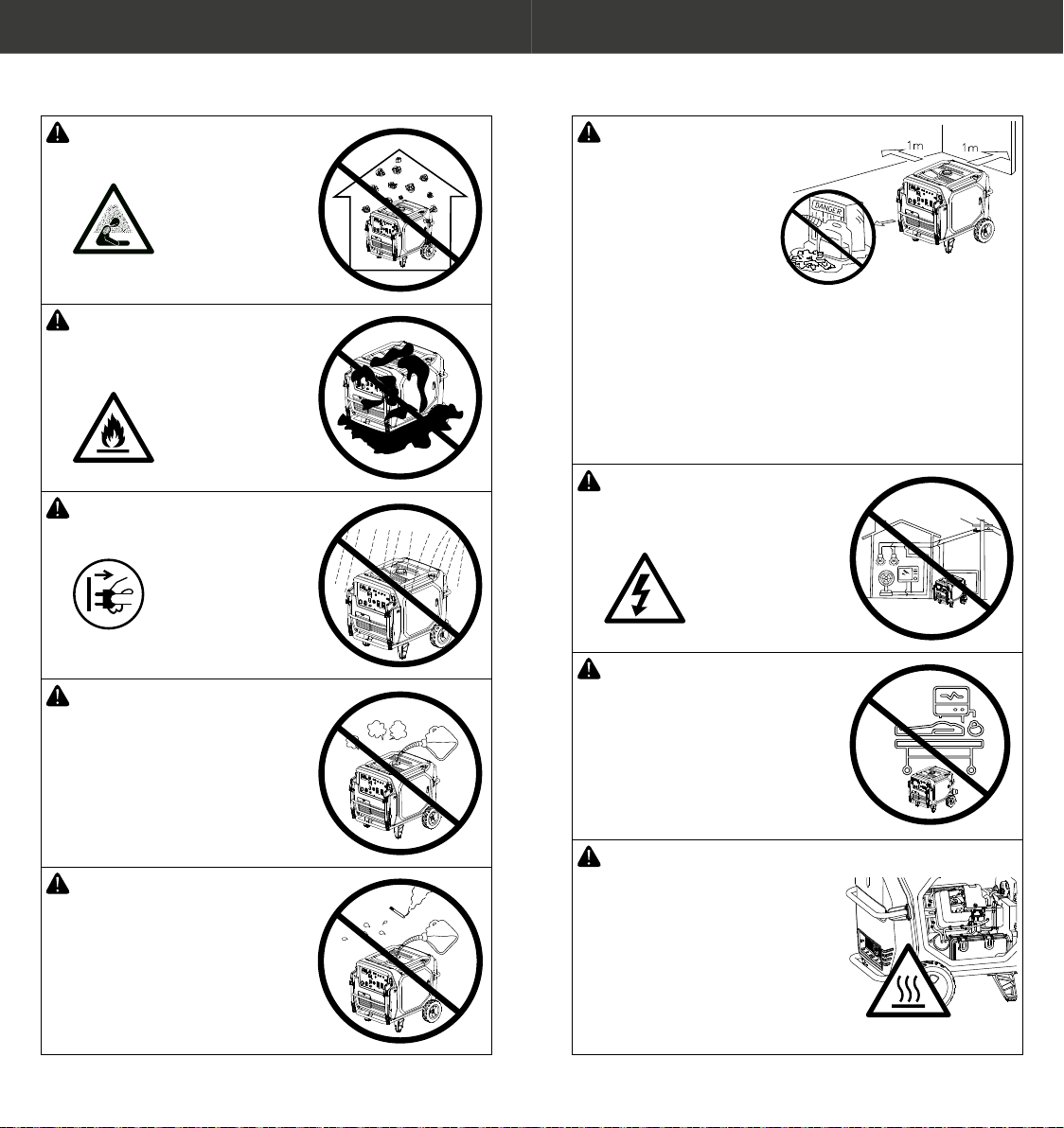
SAFETY INFORMATION
DANGER
Do not use indoors.
DANGER:
Keep the machine clean and
avoid spilt combusbles,
including petrol, on it.
WARNING:
Do not use it in wet condions.
WARNING:
Turn the generator “OFF”
when refueling.
WARNING:
Do not smoke while refueling.
WARNING:
Keep children and
pets away from the
area of operaon.
Do not place
ammable objects
close to the exhaust
when generator is
operang. Keep at
least one metre away
from ammable
materials. Do not use
in conned spaces.
WARNING:
Do not connect to a home
power system.
WARNING: This generator
is not designed for medical
applicaons.
WARNING: Hot Surfaces.
When the generator is running
or just aer stopping, it will
have hot surfaces which if
touched can cause burns. Do
not touch areas where this
warning symbol is located.
Also, avoid contact with hot
exhaust gases.
76
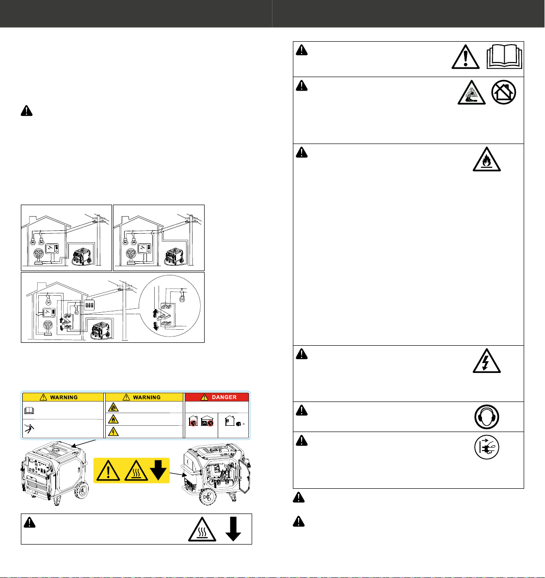
Connecon to a Home Power Supply
Connecons for standby power to a building’s electrical system
must be made by a qualied electrician. The connecon must
isolate the generator power from ulity power and must
comply with all applicable laws and electrical codes.
WARNING: Improper connecon to a building’s electrical
system can allow current from the generator to backfeed
into the ulity lines. Such backfeed may electrocute
people who come into contact with the lines during
the power outage, such as ulity company workers.
Furthermore, the generator may explode, burn or cause
res when power is restored. Consult the ulity company
or a qualied electrician prior to making any power
connecons.
RIGHT
RIGHT
WRONG
Safety Regulaons
There are warning labels on the machine to remind you of
safety regulaons.
NEVER USE INSIDE a home
or garage. EVEN IF doors
and windows are open.
ONLY USE OUTDOORS
and far away from
windows, doors & vents.
READ THE OPERATION MANUAL BEFORE USE
Pay attention to important safety and health
warnings and instructions.
■Understand and follow warnings and cautions.
■Do not operate unless guards are in place.
HIGH VOLTAGE GENERATOR
■Do not connect to any building electrical system.
■Do not overload generator.
■Non-qualified people (including under-aged
children) are not allowed to operate.
EXHAUST FUMES ARE POISONOUS
■Do not operate in unventilated areas.
■ Carbon monoxide (CO) danger.
Using a generator indoors CAN KILL IN MINUTES.
Generator exhaust contains carbon monoxide.
This is a poison you cannot see or smell.
PETROL AND ITS VAPOUR ARE
FLAMMABLE AND EXPLOSIVE
■Keep away from heat, sparks & flame sources.
■DO NOT refuel when operating.
GENERATORS PRODUCE ELECTRICITY THAT
CAN CAUSE SERIOUS INJURY OR DEATH
■Operate only in dry areas away from
moisture, rain, snow and standing water.
CAUTION: Hot Surfaces.
CAUTION: Read the safety
instrucons before using the
generator.
CAUTION: Gases such as carbon
monoxide (colourless and odourless
gas) are produced during operaon
which may lead to suocaon. Only
use the generator in well-venlated
areas.
CAUTION: Fuel is highly ammable
and extremely explosive. Fire or
explosion can cause severe burns
or death. Keep ammable items
away while handling fuel. Fill
fuel tank outdoors and in a well-
venlated area with the generator
stopped. Always wipe o spilled
fuel and wait unl the fuel has dried
before starng the generator. Do
not operate the generator with
known leaks in the fuel system. Use
proper fuel storage and handling
procedures. Do not store fuel or
other ammable materials nearby.
Empty the fuel tank before storing
or transporng the generator. Keep
re exnguisher handy and be
prepared if a re starts.
WARNING: Dangerous voltages
are present when the generator is
in operaon. The generator must
always be switched o before
performing maintenance.
CAUTION: Wear ear protecon
when operang the generator.
CAUTION: Disconnect all devices
from the connecons before
performing maintenance works,
before leaving the device and aer
switching it o.
WARNING: Modicaons to any part of the generator is
not allowed and may void your warranty.
WARNING: This generator is intended for residenal
consumer use only. This generator is not designed for
permanent installaon.
98
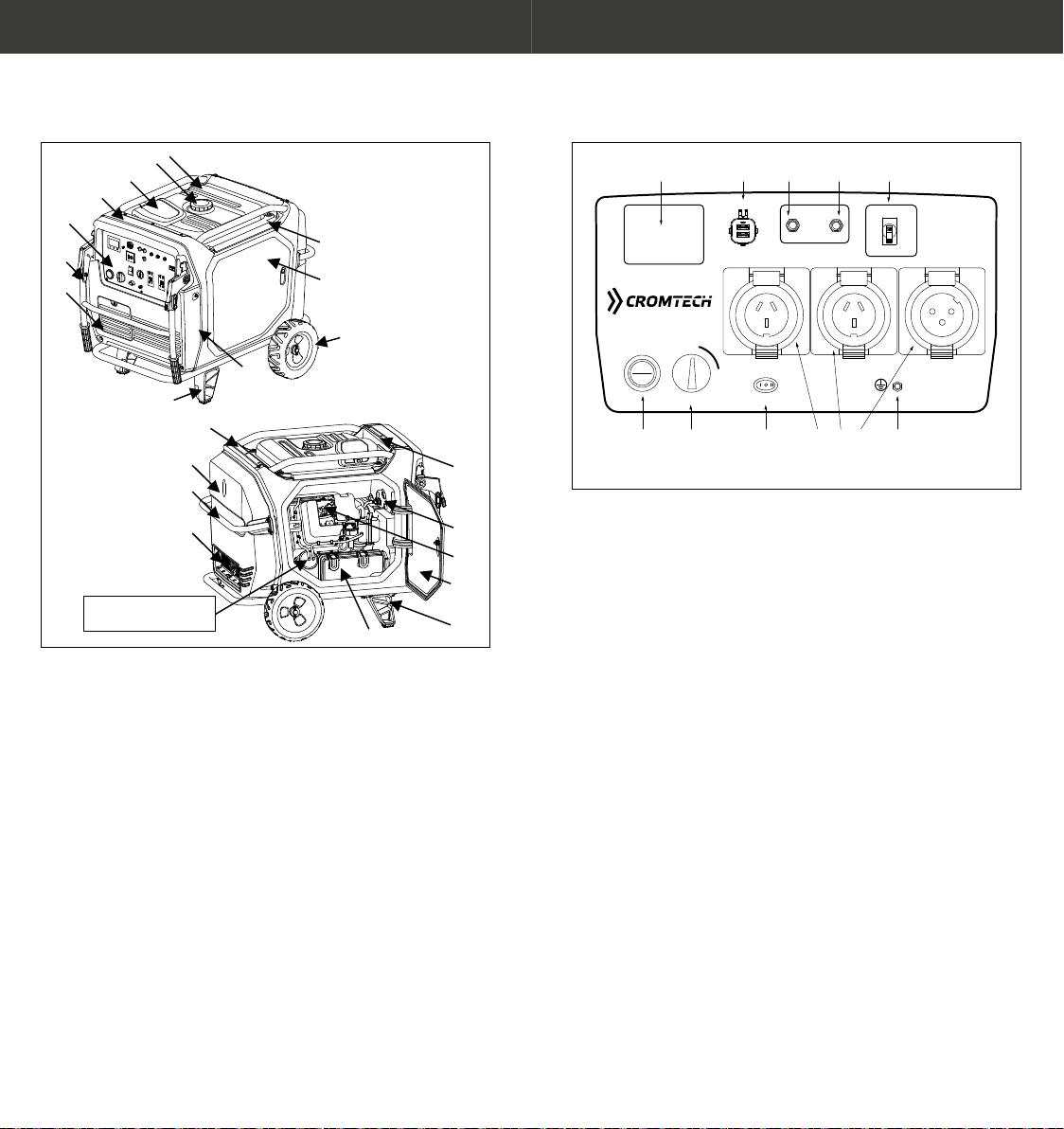
CONTROL FUNCTION
TG7000ie Diagram
(1)
(2)
(3)
(4)
(5)
(6)
(7)
(8)
(9)
(11)
(10)
(12)
(13)
(14)
(15)
(16)
(17) (18)
(19)
(20)
(21)
(22)
Serial No. T***YYMM********
The YYMM is year and month
of manufacture.
(1) Fuel tank
(2) Fuel tank cap
(3) Cover plate of oil level sensor
(4) Frame components
(5) Control panel
(6) Folding handle
(7) Baery maintenance cover
(8) Frame shock absorber bracket (right)
(9) Panel bed
(10) Wheel
(11) Right maintenance door
(12) Seal ring (fuel tank)
(13) Tank cover (back)
(14) Frame hood
(15) Handle
(16) Silencer spark collector
(17) Air lter
(18) Frame shock absorber bracket (le)
(19) Le maintenance door
(20) Spark plug
(21) Combinaon switch
(22) Tank cover (front)
Control Panel Diagram
1 2 3 4 5
6 9 10 11 127 8
INVERTER
GENERATOR 7000ie
7000ie
ESC THROTTLE
GROUND
DIGI TAL DISPLAY METER
5V 1A/ 2.1A
TOTAL 3 A MAX
USB
AC BREA KER
AC 24 0V 15A
AC BREA KER
ENGINE
STANDARD
TURBO
START
STOP
ECO
ON
ON
OFF
OFF
15A 15 A
25A
AC 24 0V 15A AC 24 0V 25A
(1) Digital display meter
(2) USB charging port
(3) AC breaker 15 amp
(4) AC breaker 15 amp
(5) AC breaker 25 amp for 32 amp outlet
(6) Engine Stop/Start Buon
(7) Engine Switch
(8) ESC Throle Switch
(9) AC socket 15 amp
(10) AC socket 15 amp
(11) AC socket 32 amp
(12) Earth terminal

1110
Engine Switch
OFF
ENGINE SW.
ON
This switch controls ignion system, fuel system, power
system and solenoid valve.
OFF Stop the engine: Ignion system is in the closed state,
fuel switch is o, solenoid valve switch is o, and power
system switch is o; the engine can’t be started normally.
ON Start/run the engine: Ignion system is in the working
state, fuel switch is on, solenoid valve switch is on, and
power system switch is on. The engine can be started by
the Start Buon, the Recoil Starter or the Bluetooth App.
Start Buon
START
____________
STOP
ON
OFF
When the engine switch is placed in the “ON” posion, use
the Start Buon to start the engine.
Recoil Starter
When baery voltage is too low or at, use the manual recoil
starter to start the engine.
ESC Throle Switch
ESC THROTTLE
STANDARD
TURBO
ECO
1 2 3
①“ECO”
When the ESC switch is turned to “ECO”, the economy
control unit controls the engine speed according to the
connected load. The results are beer fuel consumpon
and less noise.
②“STANDARD”
When the energy saving switch is placed in the
“STANDARD” posion, with load less than 4.5kW, the
engine runs at the rated speed (3,100r/min).
③“TURBO”
When the energy saving switch is placed on the posion
of “TURBO” the engine runs at the rated speed (3,600r/
min) regardless of whether the load is connected or not.
NOTE: When high current devices are applied, such as air
conditioners, hotplates or water pumps, ESC Throle must
be placed in the “TURBO” posion.
1312
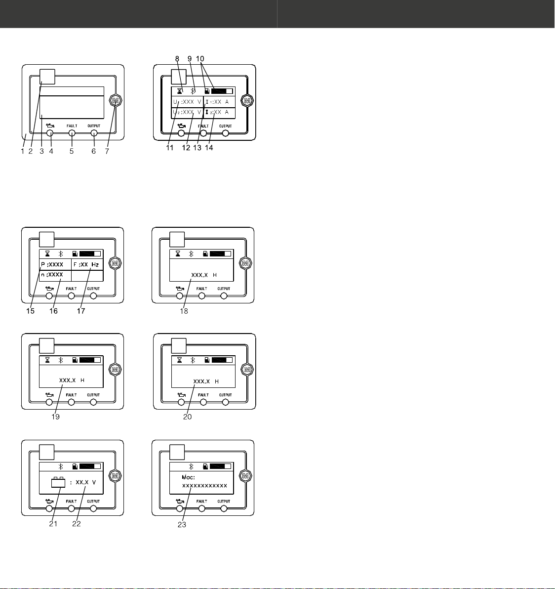
Digital Display Meter
(1) Multimeter
(2) QR Code for Bluetooth Connection
(3) LCD screen
(4) Oil warning light
(5) Overload indicator light
(6) AC pilot light
(7) Operating key
(15) Power (16) Speed (17) Frequency (18) Current run time
(19) Cumulative running time
(21) Battery normal
(22) Battery (Voltage greater than 10V)
(23) MAC address
(20) Remaining run lime
(8) Operation identification
(Normal operation)
(9) Bluetooth logo
(10) Fuel level
(11) AC Voltage
(12) AC Voltage
(13) AC Current
(14) AC Current
1. When the Engine Switch is placed in the “OFF” posion
(when the engine is not started):
Operate key 7, only the content of 19 is displayed on the
screen interface (aer each operaon of key 7, the display
will disappear automacally aer 5 seconds).
2. When the engine is not started, but the switch is in the
“ON” posion:
a. No content is displayed on the screen interface.
NOTE: If the baery has been installed, this interface
indicates that the baery voltage is less than 8V
(the baery needs to be charged), one-key start and
Bluetooth APP start cannot be carried out, but the
engine can be started by recoil starter. If there is no
display aer replacing the baery with new one,
please contact your dealer.
b. The screen interface displays the contents of 21-22
and 23 (2 display interfaces in total).
NOTE: The interface with the display contents of 21-
22 indicates that the baery voltage is more than 10V,
one-key start and Bluetooth APP start can be carried
out.
c. The screen interface displays the contents of 24-26
and 23 (2 display interfaces in total).
NOTE: The interface with the display content of 24-26
indicates that the baery voltage is more than 8V but
less than 10V, one-key start and Bluetooth APP start
cannot be carried out, but the engine can be started
by recoil starter.
NOTE: The interface with the display content of 23 can
be used for connecng the MAC address of Bluetooth
device.
The display interface can be switched by operaon of
key 7, and the contents are displayed in turn.
When the above contents are displayed in each
display interface, the contents of 27, 9 (displayed with
Bluetooth, not displayed without Bluetooth) and 10
are also displayed at the same me.
3. When the Engine Switch is placed in the “ON” posion,
and the engine starts successfully and runs normally: the
screen interface displays the contents of 11-14, 15-17, 18,
19, 20, 21-22 and 23 (7 display interfaces in total).

1514
(24) Operation identification (Not running)
(25) Battery (loss of) capacity
(26) Manual start information
(27) Battery (More than 8V / less than 10V)
(29) Fault identification
(30) Fault code symbol
(31) Maintenance identification
(28) Maintenance
NOTE: The interface content of 23 is used for the MAC
address of connecng Bluetooth device.
The display interface can be switched by operaon of key
7, and the contents are displayed in turn.
When the above contents are displayed in each display
interface, the contents of 8, 9 (displayed with Bluetooth,
not displayed without Bluetooth) and 10 are also displayed
at the same me.
4. When engine runs with failure: the screen interface
displays the contents of 29-30, and the content of 30
represents the fault informaon as follows:
U> a: AC over voltage, indicang the character of AC
(alternave indicaon of AC and digit)
U< a: AC under-voltage, indicang the character of AC
(alternave indicaon of AC and digit)
I> Output over current of generator.
Output short circuit of generator.
Over heat of frequency converter.
NOTE: When the above contents are displayed in each
display interface, the contents of 9 (displayed with
Bluetooth) and 10 are also displayed at the same me.
5. When the engine switch is in the “ON” posion, and the
engine is either running or not, the screen interface will
display content 28 advising a service interval is required.
If the service has already been carried out , operate key 7
to clear this informaon.
NOTE: Operate key 7 to clear the maintenance
informaon, the screen automacally switches to the next
interface.
If key 7 is not operated to clear the maintenance
informaon, the content of 28 will be displayed once every
1 minute in each screen interface for 10 seconds and the
content of 28 will not be displayed again unl 2 hours
later. At the same me, the maintenance mark will not be
displayed on the right side of the Bluetooth mark on the
screen interface, unl the generator set is maintained and
key 7 is operated to clear the maintenance informaon.
Oil Warning Light
When the oil level falls below
the low level, the oil warning
light comes on and then the
engine stops automacally.
Unless you rell with oil, the
engine will not start again.
NOTE: If the engine stalls or does not start, turn the engine
switch to “ON” and then pull the recoil starter. If the oil
warning light ickers for a few seconds, the engine oil is
insucient. Add oil and restart.

1716
Overload Indicator Light (Red)
The overload indicator light
comes on when an overload of
a connected electrical device
is detected, the inverter
control unit overheats, or the
AC output voltage rises. Then,
the AC protector will trip,
stopping power generaon in
order to protect the generator and any connected electric
devices. The AC pilot light (Green) will go o and the overload
indicator light (Red) will stay on, but the engine will not stop
running.
When the overload indicator light comes on and power
generaon stops, proceed as follows:
1. Turn o any connected electric devices and stop the
engine.
2. Reduce the total waage of connected electric devices
within the rated output.
3. Check for blockages in the cooling air Inlet and around the
control unit. If any blockages are found remove.
4. Aer checking, restart the engine.
NOTE: The overload indicator light may come on for a few
seconds at rst when using electric devices that require
a large starng current, such as an air condioner or a
water pump. However, this is not a malfuncon.
AC Pilot Light (Green)
The AC pilot light comes on
when the engine starts and
produces power.
Ground (Earth) Terminal
The ground terminal on this
generator is connected to NON-
current carrying parts of the
generator frame and to each AC
outlet. Before aaching a
ground (earth) lead, consult with
a qualied electrician on the
intended use of this generator.
AC Circuit Breaker
The AC Circuit Breaker will trip
to protect the electric device
when current is too heavy.
Folding Handle
This generator is ed
with a folding handle
set to enable the user
to manoeuvre the
generator with ease. To
engage, li handle up
and lock handle in
place. To fold down, press down on both locking levers at the
same me and the handle will fold down. Do not use
generator with handle set in the xed posion. Do not use the
handle set to raise the generator o the ground.
Maintenance Door
Make sure that the maintenance door is closed while the
engine is running. Open and close maintenance doors for unit
maintenance.
In the case of no electrical start,
open the right maintenance
door and start the engine by
recoil starter.
Right door: Inspecon/
replacement of engine oil;
manual start.
Le door: Inspecon/
replacement of spark plugs;
inspecon/cleaning of air lter;
drain of carburetor.
Open maintenance
door: Rotate lock 90°
counterclockwise.
Close maintenance door:
Rotate lock 90° clockwise.
1918
PRE-OPERATION
NOTICE: Pre-operaon checks should be made each me
operang.
WARNING: The engine and muer will be very hot aer
the engine has been run. Avoid touching the engine and
muer while they are sll hot with any part of your body
or clothing during inspecon or repair.
Fuel
WARNING
• Fuel is highly ammable and poisonous. Check “SAFETY
INFORMATION” (See page 7) carefully before lling.
• Do not overll the fuel tank, otherwise it may overow
when the fuel warms up and expands. Aer lling make
sure the fuel tank cap is ghtened securely.
• Immediately wipe o spilled fuel with a clean cloth.
• Use only unleaded petrol.
Only ll tank to red full level indicator in the fuel strainer.
Recommended fuel: Unleaded gasoline
Fuel tank capacity (total): 25.0 litres
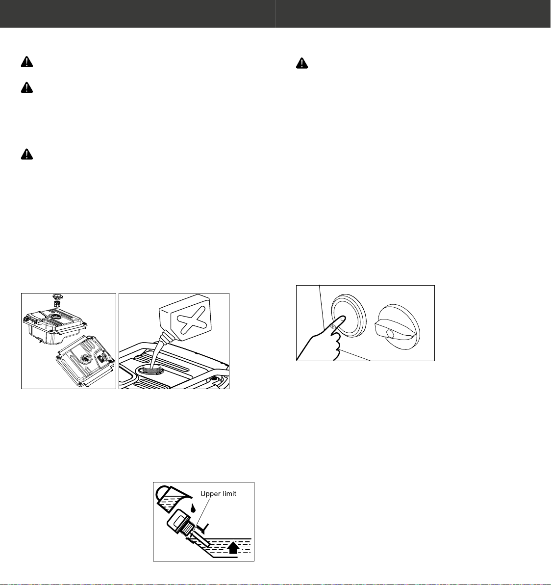
ADD FUEL
Engine Oil
The generator has been shipped without engine oil. Do not
start the engine unl lled to the correct level.
Do not lt the generator when adding oil to the engine. This
could result in overlling and damage to the engine.
OIL LEVEL
Recommended engine oil:
SAE 10W – 30
Engine oil quanty: 1.45 litres
OPERATION
NOTICE: Never operate the engine in a closed area or
it may cause unconsciousness and death within a short
me. Operate the engine in a well venlated area. The
generator has been shipped without engine oil. Do not
start the engine unl lled to the correct level.
NOTE:The generator can be used with the rated output load
at standard atmospheric condions.
“Standard atmospheric condions” = Ambient
temperature 25°C. Barometric pressure 100kPa;
Relave humidity 30%
The output of the generator varies due to change
temperature, altude (lower air pressure at higher
altude) and humidity.
The output of the generator is reduced when the
temperature, the humidity and the altude are higher
than standard atmospheric condions.
Starng The Engine
START BUTTON
START
____________
STOP
ON
OFF
1. Do not connect any electrical equipment before starng
the generator. Turn the ESC Switch to standard.
2. Turn the Engine Switch to “ON” posion.
3. Start Buon – press and release the start switch buon
on the control panel. The start switch will start the motor
for 5 seconds. When the engine starts successfully, the
starter will stop automacally. If the engine does not start
successfully, wait at least 10 seconds before starng again.
NOTE: Do not leave the Engine Switch in the “ON” posion
when the generator is not in use or in storage. This will
aen the baery.

2120
APP START – ANDROID
1. Download and install the app by scanning the above QR
code via the phone’s camera or QR Reader and follow the
download link. Follow prompts to install.
2. Once downloaded, open the app. Enter the
“Management” tab, press the + icon and then use one of
the following three methods to connect your device.
a. Scan the QR code of the Bluetooth module on the
digital display meter.
b. Click to enter the device scanning page and let the app
automacally nd the generator. The generator must
be switched on.
c. Enter the MAC address of the Bluetooth device you
want to connect to. The MAC address can be found on
the digital display meter.
3. Aer nding the Bluetooth device, go back to the device
management page.
4. Click “Connect” to connect to the Bluetooth device. Aer
successful connecon, the model icon will become bright.
5. Enter the home tab of the mobile app and click the start
buon to start the engine.
NOTE: We recommend connecng to your generator via
opon B as a preferred method of connecng.
NOTE: You can have mulple devices paired to the device,
however only one connected at a me.
APP START – APPLE
1. On your Apple device, visit the App Store.
2. In the App Store search for “ILONCIN”.
3. When you nd ILONCIN press
“GET” to download the
generator app. Once the app is
downloaded, open. Enter the
“Management” tab, press the
+ icon and then use one of the
following three methods to
connect your device.
a. Scan the QR code of the
Bluetooth module on the
digital display meter.
b. Click to enter the device
scanning page and let the
app automacally nd the
generator. The generator
must be switched on.
c. Enter the MAC address of the Bluetooth device you
want to connect to. The MAC address can be found on
the digital display meter.
4. Aer nding the Bluetooth device, go back to the device
management page.
5. Click “Connect Now” to connect the found Bluetooth
device. Aer successful connecon, the model icon will
become bright.
6. Enter the homepage of mobile APP and click the start
buon to start the engine.
NOTE: We recommend connecng to your generator via
opon B as a preferred method of connecng.
NOTE: You can have mulple devices paired to the device,
however only one connected at a me.

2322
RECOIL START
Turn the lock 90° counter-
clockwise, and open right
maintenance door. First,
pull the recoil starter
gently, unl resistance is
felt, then pull hard. Turn
the lock 90° clockwise and
close right maintenance
door.
If you want to use the energy saving funcon, turn the ESC
Throle to the “ECO” posion aer the engine has been
running for 2-3 minutes.
Stopping The Engine
ESC
THROTTLE
STANDARD
TURBO
ECO
ENGINE
ON
OFF
To shut down the engine:
1. Turn o all electrical
equipment.
2. Turn the ESC Throle
to the “Standard”
posion.
3. Disconnect all electrical
equipment from the AC
socket.
4. Manual stopping: press
and release the start
switch buon on the
control panel. Enter the
homepage of Bluetooth
APP of the mobile
phone, click the start
buon to turn o the
engine (to skip this step
proceed to the next
step).
5. Turn the Engine Switch
to the “OFF” posion.
When the generator is not
running or not in use, put
the Engine Switch in the
“OFF” posion, otherwise the baery will aen and aect
the next one-key start.
NOTE: If the engine is to be turned o in an emergency, rotate
the Engine Switch quickly to the “OFF” posion.
2524
Alternang Current (AC) Connecon
WARNING: Be sure any electric devices are turned o
before plugging them in.
NOTICE
• Be sure all electric devices including the cable and plug
connecons are in good condion before connecon to
the generator.
• Be sure the total load is within generator rated output.
• Be sure the receptacle load current is within receptacle
rated current.
1. Start engine and make sure that AC indicator light is green.
2. Insert the plug into AC socket/
3. Make sure that AC indicator light is on.
4. Turn on the electrical equipment.
Many electric load devices require starng power above their
rated power to start.
The ESC throle must be turned to “Standard” or “Turbo”
before applying high start up loads.
• Some motorised appliances require more than their
electrical rang for startup. When an electrical motor is
started, the overload indicator (red) may come on. This
is normal if the overload indicator (red) goes o within 4
seconds. If the overload indicator (red) stays on, consult
your generator dealer.
• If the generator is connected to mulple loads or
electricity consumers, please remember to rst connect
the one with the highest starng current. And last connect
the one with the lowest starng current.
• If the generator is overload, or if there is a short circuit in
a connected appliance, the overload indicator (red) will
go ON. The overload indicator (red) will stay ON, and aer
about 4 seconds, current to the connected appliance (s)
will shut o, and the output indicator (green) will go OFF.
Stop engine and invesgate the problem. Determine if
the cause is a short circuit in a connected appliance or an
overload, correct the problem and restart the generator.
MAINTENANCE
It is the owners requirement to periodically inspect, adjust,
lubricate and maintain the generator to keep it in good
working condion.
WARNING: Turn ENGINE SWITCH to “OFF” to avoid any
accidental start up during all maintenance procedures.
Stop the engine and allow the engine to cool before
starng maintenance work.
NOTE: Use only genuine replacement parts, contact your local
authorised service agent.
NOTE: Consult your local authorised service agent for all
major maintenance work.
Roune maintenance
cycle (1) Each
check
First
months
or 20 Hr
3 months
or 50 Hr 6 months
or 100 Hr 12 months
or 300 Hr
Item Roune
Oil Inspect ●
Replace ● ●
Air lter
Inspect ●
Clean ●(2)
Replace ●*
Spark plug Clean
Replace ●
Spark arrester Clean ●
Valve
clearance
Inspect-
Adjustment ●(3)
Combuson
chamber Clean Every 1000 hours (3)
Fuel tank Clean Every 2 years or 1000 hours (3)
Fuel lter Replace Every 2 years or 1000 hours (3)
Fuel hose Clean Every 2 years (Replacement if necessary) (3)
Tip: *Replace the paper lter element.
Refueling
WARNING: Petrol is ammable and explosive.
When refueling you can get burns or serious injuries.
Before refuelling, stop engine
and allow to cool.
• Only refuel outdoors
• Clean up any spilled fuel
and allow to dry
• Do not over ll the fuel
tank. Only ll tank to red
full level indicator in the
fuel strainer.
NOTICE: Petrol can damage paint and plascs.
When refueling, take care not to spill petrol.

2726
Engine Oil Inspecon
Check engine oil when engine is stopped and placed on a level
surface.
1. Rotate the lock 90° counter clockwise, and open right
maintenance door.
2. Remove the oil gauge.
3. Check the oil. If the oil level is below the highest mark, add
the specied oil to the highest mark.
4. Reinstall the oil gauge.
5. Rotate the lock 90° clockwise and close right maintenance
door.
Low oil shut down. If the engine oil is too low, the engine
will automacally shut down to protect the engine. To avoid
unnecessary engine shutdowns, check oil levels regularly.
Engine Oil Replacement
1. Rotate the lock 90° counterclockwise and open right
maintenance door.
2. Remove the black rubber seal ring under the oil drain bolt.
3. A suitable container for oil is placed at the boom of the
engine.
4. Remove the oil gauge.
5. Remove oil drain bolt and washers to drain oil thoroughly.
6. Reinstall the oil drain bolts and washers and ghten the oil
drain bolt.
7. Reinstall the black rubber seal ring.
8. Place the generator on a horizontal surface and add the
specied oil to the maximum scale.
9. Reinstall the oil gauge.
10. Rotate the lock 90° clockwise and close right maintenance
door.
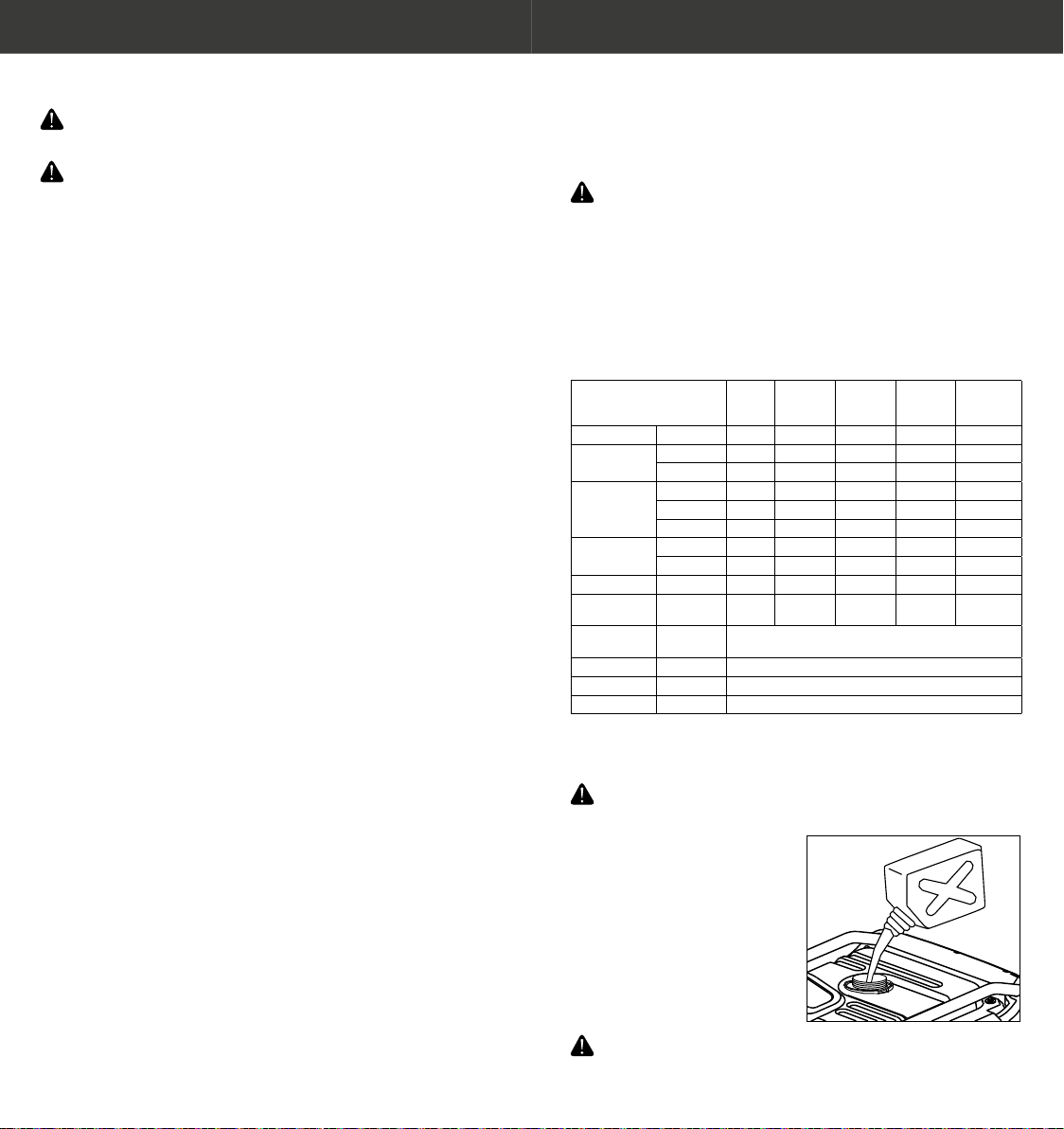
Oil Specicaon Table
Use four-stroke oil.
SAE 10W30 is
recommended for regular
use. However, when the
average temperature in
your area is within the
recommended range, you
can use other viscosity
types of oil shown in the
chart.
Air Filter
1. Rotate the lock 90° counter clockwise, and open le
maintenance door.
2. Loosen the air lter cover clamp and remove the air lter
cover, foam lter core, lter core bracket and paper lter
core together.
3. Paper lter element:
a. Remove the paper lter element from the lter holder.
b. If the paper lter element is dirty, replace it with a new
one. Do not wash the paper lter element.
c. Insert the paper lter element into the lter holder.
4. Foam lter:
a. Remove the foam lter element from the empty lter
cover.
b. Check the foam air lter to make sure that it is clean
and in good condion. If the foam lter element is
dirty, refer to the following page for cleaning. If the
foam lter element is damaged, replace it with a new
one.
5. Put the foam lter element, the lter holder and the paper
lter element together into the empty lter cover.
6. Install the air lter cover and lock the cover clamp.
7. Close the le maintenance door, and rotate the lock 90°
clockwise.
2928
AIR FILTER CLEANING
NOTICE: Do not operate the engine without an air cleaner
element as this will cause damage to the inner parts of
the engine. In unusually dusty condions regular cleaning
or replacing is required.
The foam lter element of the dirty air lter will restrict the air
ow to the fuel system and reduce the engine performance.
If the generator is used in a dusty area, the maintenance
frequency of the air lter’s foam lter element is higher than
that in the maintenance requirements.
1. Wash the lter element in warm soapy water and let it dry
naturally, or clean and dry it in a non – ammable solvent.
2. Dip the lter element into clean oil and squeeze out excess
oil. If there is too much oil le in the lter element, start
the engine and the engine will smoke.
3. Use a damp cloth to remove dirt from the inside of the air
lter’s cover. Take care to prevent dust from entering the
air ducts which leads to the fuel system.
Spark Arrester
The spark arrester must be cleaned every 100 hours to
maintain engine performance. Ensure exhaust outlet and
engine is cold before cleaning and maintenance.
To remove and clean the spark arrester.
1. Loosen two M5x12 pan head bolts and remove mounng
cover, muer mesh cover and spark collector.
2. Clean the muer’s mesh cover and the cumulave carbon
on the spark collector with a steel wire brush.
3. Ret and ghten the spark arrester.
NOTICE: Clean with steel wire brush gently to avoid
damage or scratch to muer mesh and spark arrester.
The spark arrester must not be broken or cracked. If it is
damaged, it must be replaced.
Spark Plug
NOTICE: Incorrect spark plug can cause damage to the
engine.
To replace or clean the spark plug use the spark plug spanner
kit supplied. Allow engine to cool before aempng to
remove the spark plug.
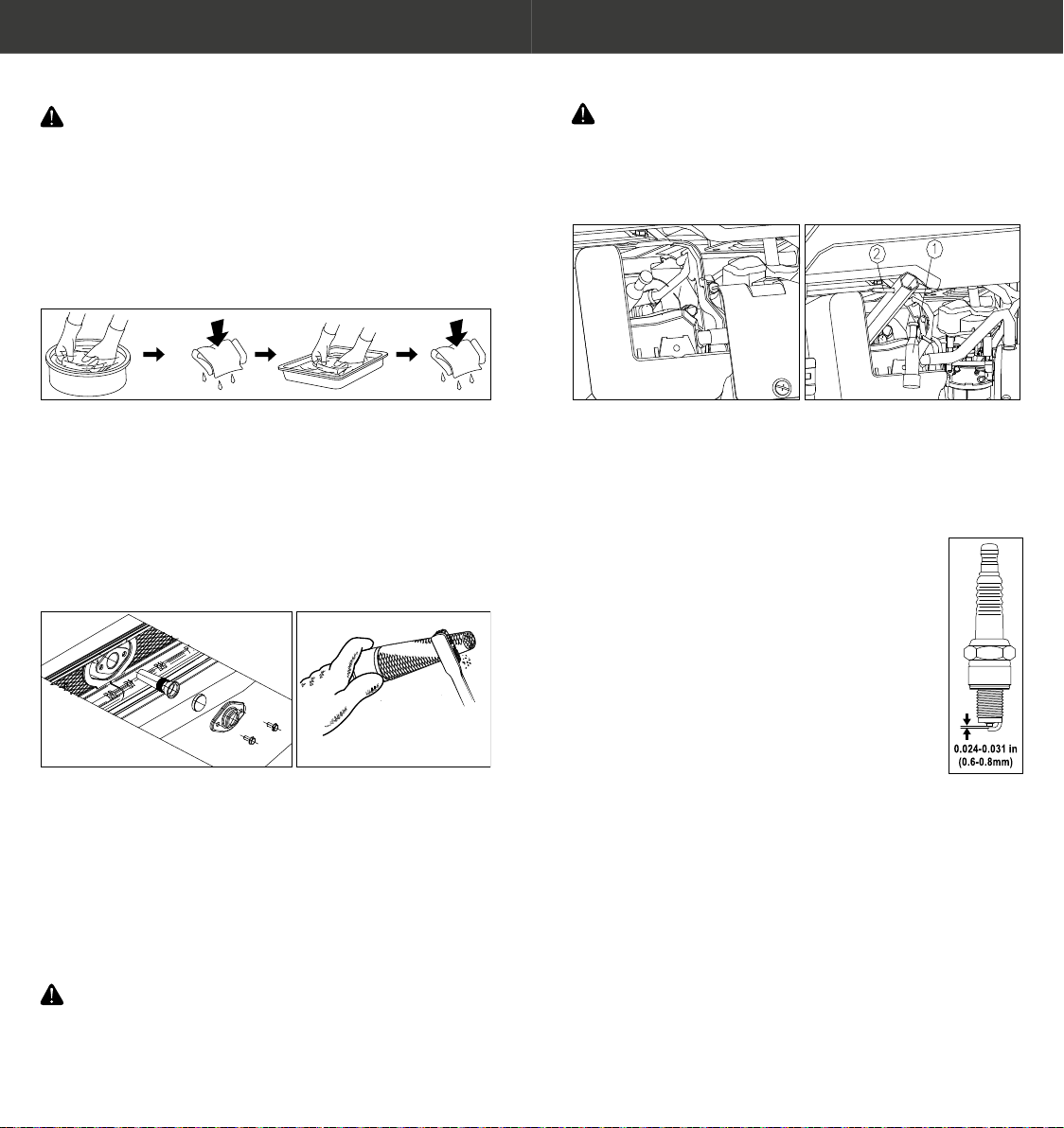
1. Rotate the lock 90° counterclockwise, and open le
maintenance door.
2. Loosen bolt of spark plug’s maintenance cover and remove.
3. Remove the spark plug cap, remove dirt and dust from
around the spark plug.
4. Use the spark plug spanner and rotate counter-clockwise
and remove the spark plug.
5. Check the spark plugs. Replace the spark plug,
if the electrode is worn or burnt, or if the
insulator is cracked or broken. Standard spark
plug: NGK BPR7ES, clearance of spark plug:
0.6-0.8mm.
6. Aer ensuring that the spark plug is in good
condion, x the spark plug gently to the
head of the cylinder by hand to prevent
thread damage caused by force.
7. Aer the spark plug is xed, ghten it with the
spark plug spanner. If the used spark plug is to
be reinstalled, ghten 1/8-1/4 circle manually
aer xing the spark plug and before
ghtening it to the specied posion. If the newly installed
spark plug is to be reinstalled, ghten 1/2 circle manually
aer xing the spark plug and before ghtening it to the
specied posion. Torque: 13.3 LBS. Ft (18 N.M, 1.8kg.m)
8. Install the spark plug cap.
9. Install spark plug maintenance cover and ghten
maintenance cover’s bolts.
10. Close the le maintenance door, and rotate the lock 90°
clockwise.
NOTE: Spark Plug Type: NGK BPR7ES
NOTE: If the spark plug is installed without torque wrench, a
beer esmaon method is to ghten 1/4-1/2 circle
manually, but the spark plug should be ghtened to the
specied torque.

3130
NOTICE: Loose spark plugs may overheat and damage the
engine. Excessive ghtening of spark plugs can damage
the thread on the head of cylinder.
Baery
When the engine is running, the generator’s charging
system will automacally charge the baery. However, if the
generator is not used regularly, it must be charged monthly to
maintain the service life of the baery.
REMOVING THE BATTERY
1. Li handle up, lock handle and x it in place.
2. Loosen the bolts of maintenance cover and remove the
baery maintenance cover CD.
3. Remove the negave (-) cable from the negave (-)
terminal of the baery, and then remove the posive (+)
cable from the posive (+) terminal of the baery.
4. Remove the baery band from the hook at the boom of
generator.
5. Remove the baery from the mounng box.
INSTALLING THE BATTERY
1. Put the baery
in the mounng box.
2. Connect the posive
(+) cable with the
posive (+) terminal
of the baery, ghten
the bolt and cover
the rubber cap.
3. Connect the negave (-) cable with the negave (-)
terminal of the baery, and ghten the installaon bolt.
4. Install the baery band.
5. Reinstall baery maintenance cover and ghten the bolts.
NOTICE: The generator must not run without the baery
maintenance cover ed as this will aect the internal
cooling air ow of the generator and will void the warranty.
CAUTION: Baery Terminals and leads may have a build
up of dirt and corrosion. Wash hands immedialtey aer
handling the baery.
Protecve Fuses
If the fuse blows, the generator will stop.
In the case of a fuse failure, nd out the cause of the failure
and x it before connuing to use. If the fuse connues to fail,
stop using the generator and contact the dealer.
1. Turn the Engine Switch to the “OFF” posion, before
checking and replacing the fuse.
2. Loosen the bolts of baery maintenance cover, remove
the baery maintenance cover CD.
3. Open the cover of the fuse mounng box® (90°
counterclockwise)
4. Replace the fuse with the one of the same type and grade.
Specicaons of fuse: SA, 20A.
5. Cover the fuse mounng box and install the baery
maintenance cover.
NOTICE: Only use the specied, rated and type of fuse as
ed as this may cause damage to the electrical system
and will void the warranty.
3332
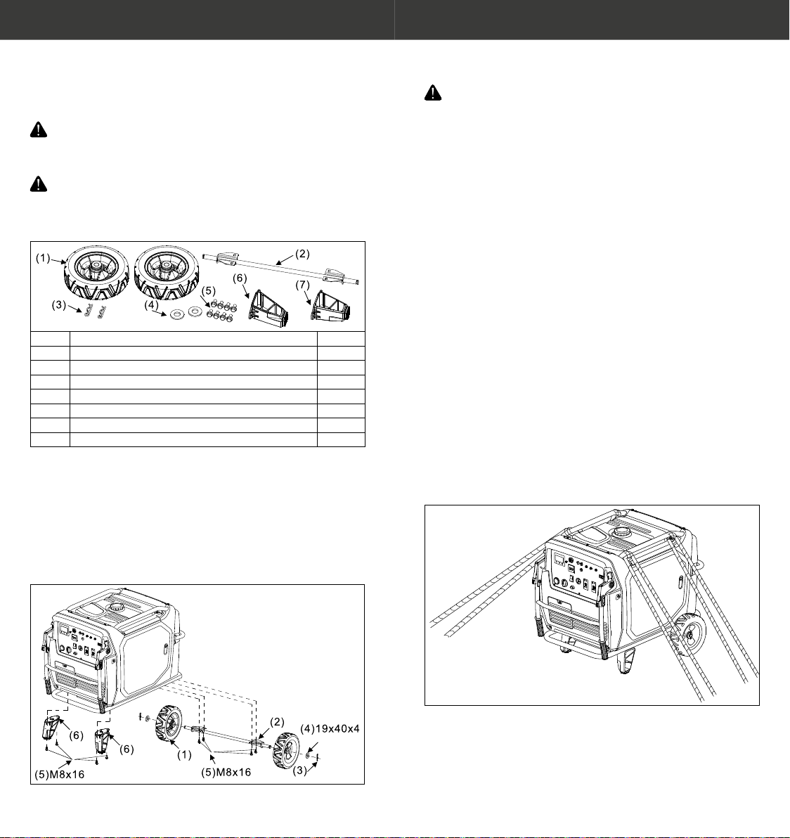
WHEEL SET INSTALLATION
Tool requirements: 12mm wrench, 10mm wrench, crosshead
screwdriver used for baery wiring, and clamp.
NOTICE: The generator must not be run without the
wheel kit ed as the wheel kit provides airow between
the ground and the airow inlet of the generator.
WARNING: If the wheel kit is not installed dust and debris
may be drawn into the air intake of the generator. This
will cause major damage to the generator and will void
the warranty.
No. Name Quanty
1Wheel 2
2Axle 1
3B pin 2
4Washer 2
5Bolt 8
6Frame shock absorber bracket (le) 1
7Frame shock absorber bracket (right) 1
1. Install the wheels to the generator with two washers and
pin clamps.
2. Install the axle onto the generator with four M8x 16 bolts.
3. Install the frame shock absorber bracket (le) onto the
generator with two M8x16 bolts.
4. Install the frame shock absorber bracket (right) onto the
generator with two M8x16 bolts.
Torque: 11-16 LBS. Ft (15-22 N.M, 1.5-2.2kg.m).
TRANSPORTING
TRANSPORTATION
Before transportaon allow the generator set to cool
completely.
To prevent fuel spillage, when transporng or during
temporary storage, the generator should be secured upright
in its normal operang posion, with the all switches in the
“OFF” posion
Do not overll the tank. Do not operate the generator while it
is on a vehicle. Take the generator o the vehicle and use it in
a well-venlated place.
Avoid a place exposed to direct sunlight when pung the
generator on a vehicle.
If the generator is le in an enclosed vehicle for many hours,
high temperature inside the vehicle could cause fuel to
vaporize, resulng in a possible explosion.
Do not drive on a rough road for an extended period with the
generator on board. If you must transport the generator on a
rough road, drain the fuel from the generator beforehand.
Note: Take care not to drop or strike the generator during
transport. Do not place heavy objects on the generator. When
using e-downs to secure the generator for transportaon,
use only the two upper frame protecon bars to aach to. Do
not aach e-downs to the main body of the generator or to
any part of the folding handle.

3534
STORAGE
In order to keep your generator trouble-free and in good
condion, proper storage preparaon is essenal. The
following steps will help to make it easier to start the engine
when you use the generator again.
Fuel
NOTICE: Fuel will deteriorate and oxidise over me. It is
important to remove fuel for longer term storage. Engine
failure due to stale fuel is not covered by warranty.
DRAINING THE FUEL
1. Remove fuel tank cap and fuel lter screen and extract
fuel into an appropriate container. Note: Fuel is extremely
volale and dangerous. Handle with cauon.
2. Turn the Engine Switch to the “ON” posion.
3. Start the engine and let it run unl the fuel runs out. The
engine will automacally stop.
4. Allow engine and generator to cool completely before
proceeding with next steps.
5. Unlock and open the le maintenance door.
6. Loosen the drain bolt on the carbureor and drain the fuel
into an appropriate container.
7. Turn the Engine Switch to the “OFF” posion.
8. Tighten the drain bolt on the carbureor.
9. Close and lock maintenance door.
Engine
• Remove the spark plug and pour about 15 ml of oil into
the cylinder.
• Turn the Engine Switch to the “OFF” posion.
• Crank the engine by pulling the manual recoil starter a few
mes to lubricate the cylinder.
• Ret the spark plug and maintenance cover.
• Clean and store the unit in a dry, dust free area out of
direct sunlight.
TROUBLESHOOTING
No. Fault Soluon
ENGINE WON’T START
1The Engine Switch is placed on the
"O" posion.
Turn the Engine Switch to the "On"
posion.
2Not enough fuel in the tank. Add fuel.
3Old or stale fuel. Drain the fuel from the tank, and
rell with new gasoline.
4Too low oil level causes the oil
alarm system to operate.
Add engine oil.
5No spark. Remove and clean or replace worn
or damaged spark plug.
6Ignion system fault, wiring harness
fault, valve clearance, etc.
Contact dealer
DECREASE OF OUTPUT POWER
1Air lter element failure Clean or replace lter element.
2Ignion system fault, wiring harness
fault, valve clearance, etc.
Contact dealers for handling.
NO OUTPUT OF CONTROL PANEL
1AC indicator light is o, and
overload indicator light is on.
Check AC load. Stop and restart the
engine.
Check the inlet of cooling vent.
Stop and restart the engine.
2AC Over-load buon trips out. Remove load and reset AC buon.
Check appliance before replugging
in.
3Other engine faults. Contact dealers for handling.
3736
SPECIFICATIONS
Model No. TG7000ie
Generator Type Inverter
Rated frequency 50Hz
Rated voltage 240V
Maximum power MAX 7000 WATTS
Rated power COP 6000 WATTS
Power factor 1.0
THD ≤1. 5%
Noise Level dB/LpA/LwA/K 4m
(3/4 load)
70 / 90
Overload Protecon Control by inverter overload
protect program
Engine Engine LC190FD-2
Engine type Single cylinder, 4-Stroke, forced
air cooling, OHV
Displacement 420cc
Fuel type Unleaded Petrol
Fuel capacity 25 litres
Connuous Running Time (at
rated power)
6.5 hours
Oil Capacity 1.45 litres
Spark Model No. NGK BPR7ES
Starng mode Recoil start/ Electric start/
APP start
Generator Length x Width x Height 950x765x773 mm
Wheel - Solid 2 x 250mm
Net weight 130kg
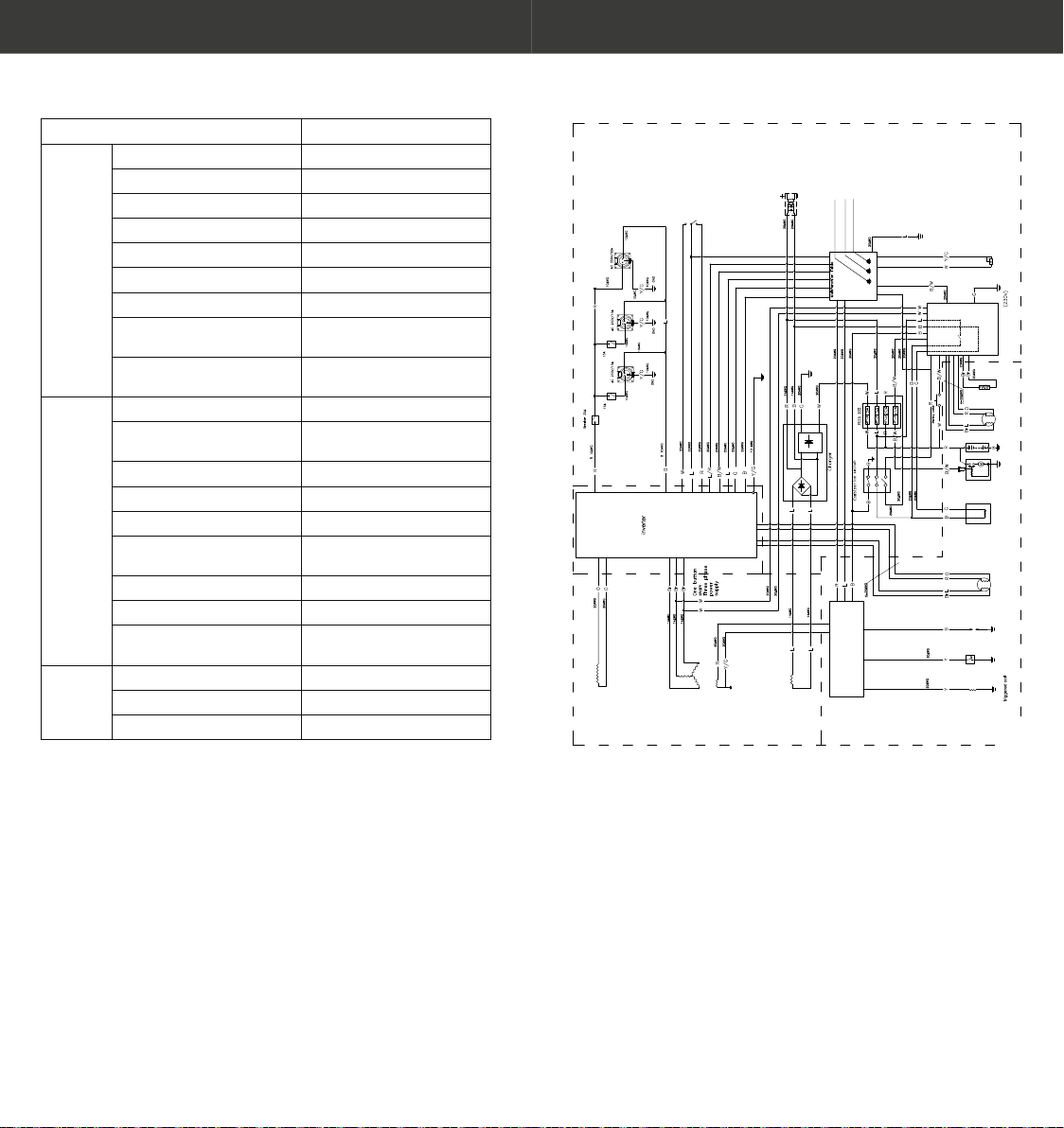
WIRING DIAGRAM
Subspoel
lgnition coil
Hoofdspoel
ESC switch
Choke
stepper motor
oil warning indicator light
overload indicator light
AC pilot light
Black
Brown
Green
Blue
Orange
Red
White
Yellow
Black/White
Yellow/Green
Red/White
B
Br
G
L
O
R
W
Y
B/W
Y/G
R/W
CONTROL PANEL BLOCK
GENERATOR BLOCK
ENGINE BLOCK
oil sensor
Ignition
spark plug stepper motor speed
Cylinder
temperture sensor
USB receptacle
Carburetor
solenoid valve Starter motor Battery start-stop controller Gasoline level sensor
DC coil
DC5V
3A
Table of contents


