MYERS LV Series User manual

1 115159H - LV I/O OPTION
Table of Contents
SECTION 1................................................................................................................................................... 2
Connecting the I/O Board.................................................................................................................... 2
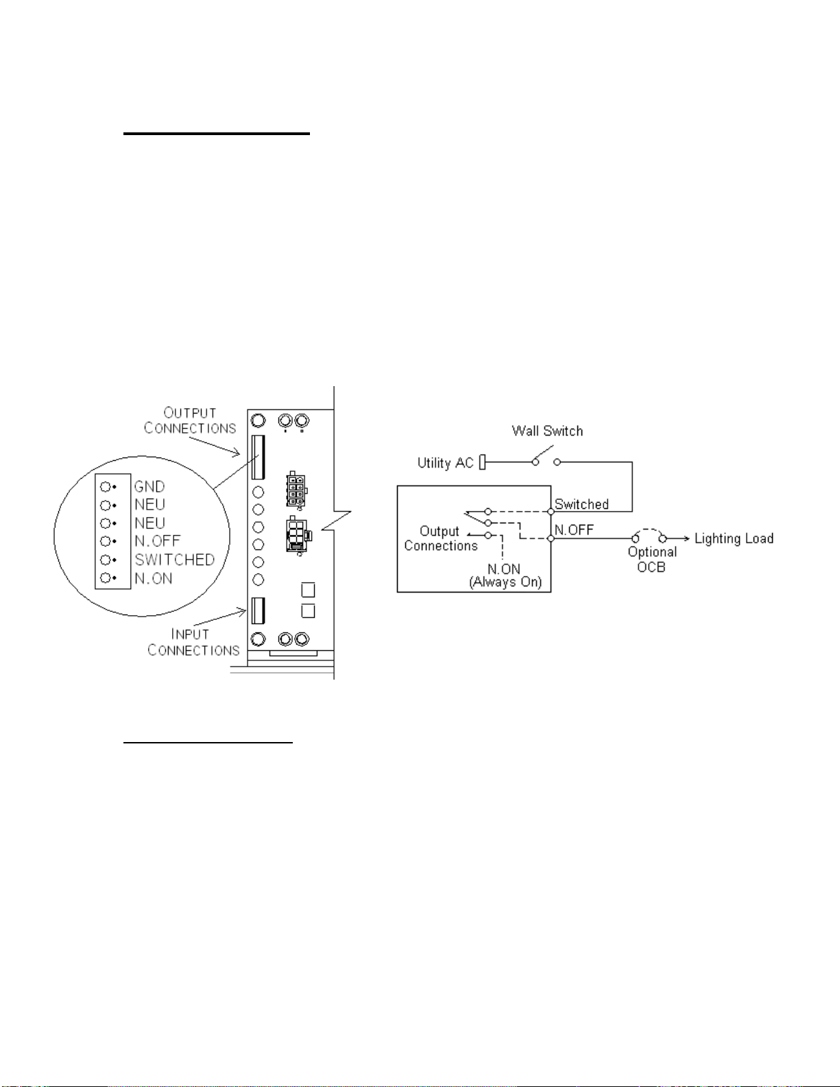
Output Connections: ........................................................................................................................ 3
Input Connections:............................................................................................................................ 3
SECTION 2................................................................................................................................................... 3
Navigating the I/O Board settings ..................................................................................................... 3
To ensure that an I/O option is present:...................................................................................... 3
To set an input function:.................................................................................................................. 3
To set an output function:............................................................................................................... 4
To view the status of inputs and outputs: .................................................................................. 4
Default settings:................................................................................................................................. 4
SECTION 3................................................................................................................................................... 5
Input functions defined........................................................................................................................ 5
Indicator (IND): ................................................................................................................................... 5
Charger Disabled (CHD): ................................................................................................................. 5
Switched Output (SWO):.................................................................................................................. 5
Transfer to Battery (TTB):................................................................................................................ 5
Normally Off Relay (NOR): .............................................................................................................. 5
SECTION 4................................................................................................................................................... 6
Output functions defined..................................................................................................................... 6
Output Set Point Functions: ........................................................................................................... 6
Status/Alarm Functions:.................................................................................................................. 7
Other Output Functions:.................................................................................................................. 8
SECTION 5................................................................................................................................................... 9
Switched Outputs.................................................................................................................................. 9
Switched output without the I/O Board option: ......................................................................... 9
Non-isolated switched output with the I/O Board option:......................................................10
SECTION 6..................................................................................................................................................12
LED Dimmer Application with Switch .............................................................................................12
0-10 LED Dimmer Application (Full Brightness)...........................................................................13
0-10 LED Dimmer Application (Minimum Brightness) ................................................................14
SECTION 7..................................................................................................................................................15
Combination of output contacts.......................................................................................................15
In parallel:...........................................................................................................................................15
In series: .............................................................................................................................................16
Mixed series and parallel:...............................................................................................................16
SECTION 8..................................................................................................................................................17
Zone Monitor..........................................................................................................................................17

2 115159H - LV I/O OPTION
SECTION 1
Connecting the I/O Board
The I/O Board options for the Series LV Emergency Lighting Central Inverter can
have a varying amount of input and output connections. The two most common
versions are a version with 3 inputs and 3 outputs, and another version with 6
outputs. The following section outlines how to connect this version.
Figure 1.1 - Basic structure of I/O Board with three inputs and three outputs.
Figure 1.2 - Basic structure of I/O Board with 6 outputs.

3 115159H - LV I/O OPTION
Output Connections:
The output connections of the I/O Board option are dry contacts. These
contacts are rated for up to 277Vac at 10A and are isolated from the rest of the
Series LV system, so sources of a different phase can be controlled without
damaging components. The connection marked C on the I/O Board is the
common connection of the relay. This connection is mechanically connected to
NC when not powered, and NO when powered.
Input Connections:
The input connections of the I/O Board option detect a 90-277Vac voltage.
These inputs are isolated, so multiple sources, of various phase and voltage, can
be detected with one I/O Board. The polarity of these input connections ii not
important to the function. If at least 90VAC is applied across these connections,
a logic high will be detected. Each input can be programmed as Active Open or
Active Closed. Active Open is active when there is less than 50Vac across the
input. Active Closed is active when there is more than 90Vac across the input. A
voltage of between 50-90Vac across the input may cause the input to toggle.
The input is not intended to be used between 50-90Vac.
SECTION 2
Navigating the I/O Board settings
The inputs and outputs of the I/O Board are programmable through the
display panel of the Series LV system, which is featured on advanced systems.
The following section outlines how to set input and output functions through the
LV display panel. See the 115107 LV Series Manual for further instructions on
the display operation of the LV system.
To ensure that an I/O option is present:
Hold down the power button on the display for five seconds to power it on.
Using the arrow keys, navigate to Unit Info in the display menu.
Using the arrow keys, navigate to I/O Module in the System Setup menu.
This menu will say PRESENT if the I/O Board option is available.
This menu will say NOT PRESENT if the I/O Board option is not available.*
*If an IO board has been installed, but this menu says that it is not present, ensure that theRJ45
connectors are seated properly.
To set an input function:
Ensure that the Series LV unit is fully powered and contains an I/O Board option.
Hold down the power button on the display to power it on.
Using the arrow keys, navigate to System Setup in the display menu.
Using the arrow keys, navigate to I/O Settings in the System Setup menu.
Using the arrow keys, choose the desired input, and press the enter button.

4 115159H - LV I/O OPTION
Using the arrow keys, choose the desired function, and press enter.
Using the arrow keys, choose the appropriate Active state, and press enter.
Using the arrow keys, choose the appropriate label, and press enter.
Press escape to leave the I/O Settings menu and the changes will be updated.
To set an output function:
Ensure that the Series LV unit is fully powered and contains an I/O Board option.
Hold down the power button on the display to power it on.
Using the arrow keys, navigate to System Setup in the display menu.
Using the arrow keys, navigate to I/O Settings in the System Setup menu.
Using the arrow keys, choose the appropriate output, and press the enter button.
Using the arrow keys, choose the desired function, and press enter.
Using the arrow keys, set the required range if needed, and press enter.
Press escape to leave the I/O Settings menu and the changes will be updated.
To view the status of inputs and outputs:
Ensure that the Series LV unit is fully powered and contains an I/O Board option.
Hold down the power button on the display to power it on.
Using the arrow keys, navigate to Contact Status in the display menu.
Using the arrow keys, navigate to through the I/O in the Contact Status menu.
The menu displays the state of the contacts as well as the function they are set too.
Default settings:
The following table outlines the default settings for different versions of the
LV series I/O Option board.
Table 2.1: Default settings
•Default settings are factory programmed.
•Basic LV System I/O boards are not adjustable.
6 Output Option
3 Output / 3 Input Option
I/O
Default Setting
I/O
Default Setting
OUT1
Advanced: VAC In (Function)
(Utility VAC Nominal +14% / -15%)
IN1
Isolated Power Input
Basic: AC Present (Status)
(AC Utility above 60VAC)
OUT2
Input Fuse Failed (Alarm)
IN2
Isolated Power Input
OUT3
On Battery (Status)
(Inverter On)
IN3
Isolated Power Input
OUT4
Overload (Alarm)
(AC Output Turns Off if On Battery)
OUT1
Active when IN1 Power Present or
when On Battery
OUT5
Battery Voltage (Function)
(Near Low Battery = 1.85V / Cell)
OUT2
Active when IN2 Power Present or
when On Battery
OUT6
Test Failed (Alarm)
OUT3
Active when IN3 Power Present or
when On Battery

5 115159H - LV I/O OPTION
SECTION 3
Input functions defined
Indicator (IND):
The indicator function displays a specific indicator in the Contact Status
menu of the display and is passed through as data in the BACnet communication
option. This function does not change any parameters, nor does it perform any
other task.
Charger Disabled (CHD):
The charger disabled function stops the unit from charging the batteries.
Leaving the unit in this state will eventually cause the batteries to go into low
voltage disconnect, which will result in a power down of the unit and lose of
backup power. For this reason, this function is only intended for emergency use.
Switched Output (SWO):
The switched output function binds the selected input to the output of the
same number and creates a switched output. Whenever the selected input is
active, the output of the same number will go active. The same output will also
go active if the unit goes into emergency power. For example, if IN1 is set to the
switched output function, OUT2 will toggle active whenever IN2 goes active.
OUT2 will also go active if the unit goes into emergency power.
Transfer to Battery (TTB):
The transfer to battery function forces the unit to switch to emergency
power regardless of the utility power and return from emergency power once the
unit goes into low voltage disconnect or the selected input becomes inactive. If
the unit goes into low voltage disconnect because of this function the unit will be
locked out of transferring to inverter because of this function until the selected
input goes inactive, making this effectively an edge triggered function. This
protects the batteries from a deep discharge in the case where the transfer to
battery function is left active.
Normally Off Relay (NOR):
The normally off relay function powers the normally off relay when the
selected input is active. The contacts for this relay are labeled N.Off, N.On, and
Switched. This function works with the normally off relay controls that are
standard with a LV series emergency lighting system. If the loadshed feature of
the LV series unit is enabled, it will disable the normally off relay after a set
amount of time regardless of the active state of an input set to the normally off
relay function. Multiple inputs can be set to this function at the same time,
allowing different utility zones to control the same lighting load.

6 115159H - LV I/O OPTION
SECTION 4
Output functions defined
Output function can be broken into three categories, status/alarms, set points,
and other.
Output Set Point Functions:
Set point outputs are output functions that require the user to set limits.
Input Voltage, Input Frequency, Output Voltage, Output Current, Battery
Voltage, Battery Temperature, Ambient Temperature, and On Inverter Timer
are all set point outputs. For all of these set point functions, except On Inverter
Timer, the user defines a top limit and a bottom limit. When the value of the
selected set point falls out of the defined ranged, the output relay is powered.
For example, if an output is set to Input Voltage, and the user has defined the
input voltage range to be 102Vac-130Vac, the output contact will be powered if
the input voltage falls below 102Vac or rises above 130Vac. The On Inverter
Timer function requires that the user set a specific amount of time, rather than a
range. When the Series LV unit goes into emergency power for this specified
amount of time, the output relay is activated.
Table 4.1 Output Set Point Functions
Special considerations:
If multiple outputs are set to the same set point function, they must share
the same set points. Changing the set points for one output will change the set
points for any other outputs that are set to the same function.
Unit Size
Low Setting
High Setting
Input Voltage
120Vac
102Vac-115Vac
125Vac-137Vac
277Vac
235Vac-263Vac
290Vac-318Vac
Input Frequency
All
55Hz-59Hz
61Hz-65Hz
Output Voltage
120Vac
80Vac-115Vac
125Vac-150Vac
277Vac
185Vac-263Vac
290Vac-346Vac
Output Current
175W
0Amps-1.45Amps
XAmps-1.82Amps*
350W
0Amps-2.91Amps
XAmps-3.64Amps*
550W
0Amps-4.58Amps
XAmps-5.72Amps*
750W
0Amps-6.25Amps
XAmps-7.81Amps*
1100W
0Amps-9.17Amps
XAmps-11.46Amps*
Battery Voltage
175W
10.5Vdc-12Vdc
13.5Vdc-15Vdc
350W
21Vdc-24Vdc
27Vdc-30Vdc
550W
31.5Vdc-36Vdc
40.5Vdc-45Vdc
750W,1100W
42Vdc-48Vc
54Vdc-60Vdc
Battery Temp
All
-20°C to 10°C
40°C to 120°C
Ambient Temp
All
-20°C to 10°C
35°C to 800°C
On Inverter Timer
All
1min-255mins
**
*The range starts one increment above the lower setting
**On Inverter Timer only has one setting

7 115159H - LV I/O OPTION
Status/Alarm Functions:
Status/Alarm outputs are powered when the selected status or alarm is
triggered. Powered, Charging, On Battery, Test Active, and Norm Off Active
are available status functions. An output set to the Powered function will be
powered as long as the unit is on. If the Series LV unit is bulk, absorption, or
float charging, an output set to Charging will be powered. If the Series LV unit is
in manual test, monthly test, or a yearly test, an output set to Test Active will be
powered. If the unit is in emergency backup, any output set to On Battery will be
powered. Normally Off Active functions similarly to On Battery, except there
are options in the Normally Off Relay section of the System Setup menu that
keep the normally off load powered for a varying amount of time after the Series
LV unit returns from emergency backup. Charger, Summary, Over current,
Overload, Test Failed, Load Red, Heat sink temperature, Input Fuse Failed
are all available alarm functions. If an output is set to one of these alarms, and
the Series LV unit has this alarm, the output relay is powered.
Table 4.2 Status Functions
Status Function
Description
Powered
Engages the output relay when the LV Series unit is powered.
Charging
Engages the output relay when the LV Series unit is charging.
On Battery
Engages the output relay when the LV Series unit is in emergency backup.
Test
Engages the output relay when the LV Series unit is conducting an inverter test.
Norm Off Active
Engages the output relay when the normally off relay is powered.
AC Present
Engages the output relay when AC is greater than 60Vac
Table 4.3 Alarm Functions
Alarm Function
Description
Charger
Engages the output relay when the LV Series fails to charge correctly
Summary
Disengages the output relay when LV Series summary contact is Disengaged*
Over current
Engages the output relay when the LV Series unit is in over current.
Overload
Engages the output relay when the LV Series unit is overloaded.
Test Failed
Engages the output relay when a monthly, yearly, or manual test has failed.
Load Red
Engages the output relay when the load falls below the load reduction set point.
Heat Sink
Engages the output relay when the heat sink temperature goes about 90°C
Input Fuse Failed
Engages the output relay when the unit has an input fuse failed alarm
*Summary alarms activates the relays when the unit has no alarms, and deactivates them when
there is an alarm

8 115159H - LV I/O OPTION
Other Output Functions:
Input Active, Switched Output, and Transfer Delay are other functions
available for the output contacts. If an output is set to Input Active, it will be
powered as long as the same number input is powered. For example, if input 1
is powered with a 90-277Vac signal, output 1 will be powered.
An output set to Switched Output will be powered when the
corresponding input is powered, or when the Series LV unit goes into emergency
backup.
Note: The output is automatically set to Switched Output when an input is
defined with the Switched Output function.
Transfer Delay operates as a normally on output and will force a time
delay off of 6 seconds each time the unit transfers to battery. After the delay, the
relay will go back to a normally on state. This function is used with certain
lighting controls that require a break in power for several seconds between
normal power and battery power to detect that the inverter is in emergency
mode.

9 115159H - LV I/O OPTION
SECTION 5
Switched Outputs
There are multiple ways to accomplish a switched output function with the
Series LV Emergency lighting inverter. The following section will outline three of
the most common solutions.
Switched output without the I/O Board option:
Without an I/O Board option, the normally off feature of the unit can be used for
the switched output function.
To wire this switched output solution:
Connect the neutral wires to either of the two NEU connections.
Connect the load to the N.OFF connection.
Connect the switched line to the SWITCHED connection.
Figure 5.1 - Series LV Output Connections
Special considerations:
This switched output solution requires that the switched line mentioned is
the same phase as the input to the LV Series unit. This solution can not be
accomplished with voltages of different phases or magnitudes without damaging
the LV system.
If the LV system has a display, this switched output solution can have an
optional extended timer that is controlled by the normally off timer in the set
points menu of the display. This time extension will keep the switched output
powered for a specified amount of time after the unit returns from battery, shed
the normally off load after a specified amount of time on emergency, or set the
normally off relay dependent on the time of day.
A dimmer switch can be used in place of the switch to dim the output until
the unit goes into emergency backup. While in backup, the lighting will be full
brightness.

10 115159H - LV I/O OPTION
Non-isolated switched output with the I/O Board option:
This solution uses an I/O Board option to wire one of the I/O Board outputs
almost the same way as using the normally off relay.
To wire this switched output solution with only one output of the I/O Board:
Connect the load for the switched output to the Cconnection of the I/O Board
Output.
Connect the switched line to the NC connection of the I/O Board Output.
Connect the emergency backup line to the NO connection of the I/O Board
Output.
After wiring is completed, the output needs to be set to On Battery in the I/O
settings menu in the display. This causes the output contact to switch whenever
the unit goes into emergency backup for any reason, causing the power to
bypass the wall switch.
Figure 5.2
Special considerations:
This switched output solution requires that the switched line mentioned is
the same phase as the input to the LV Series unit. This solution can not be
accomplished with voltages of different phases or magnitudes without damaging
the LV system.
A resistive dimmer switch can be used in place of the switch to dim the
output until the unit goes into emergency backup. While in backup, the lighting
will be full brightness.
If the utility AC used to power the wall switch loses power, and the utility
source for the LV Emergency Lighting Inverter does not lose power, there may
be a loss of power for a lighting load that uses this switched output solution.

11 115159H - LV I/O OPTION
Isolated switched output with the I/O Board option:
This solution uses an I/O Board option to wire one of the I/O Board outputs with
an isolated input to detect the wall switch.
To wire this switched output solution with only one output of the I/O Board:
Connect the load for the switched output to the Cconnection.
Connect the emergency backup line to the NO connection.
Connect the switched utility line to an input of the I/O Board.
Connect the switched utility neutral to the same input of the I/O Board.
After wiring is completed, the input needs to be set to Switched Input in the I/O
settings menu in the display. This causes the output contact to switch whenever
there is a 90-277Vac voltage across the input connection of the I/O Board, or the
LV Series unit goes into emergency backup.
Figure 5.3
Special considerations:
This switched output solution is completely isolated. Any 90-277Vac
signal, regardless of phase, can be used to toggle the switched output without
damaging the LV Series unit.
A resistive dimmer can not be used to replace the wall switch with this
solution. The input detects either an on or off situation and a resistive dimmer
may cause the output contact to pulsate rather than dim.
When selecting Switched Input for the input I/O setting, the output
function of the corresponding output I/O is tied directly to the corresponding
input. This output will be locked, and it will be impossible to change this output
function without first changing the input setting to something other than Switched
Input. For example, setting input 1 of the I/O board to Switched Input locks
output 1.

12 115159H - LV I/O OPTION
SECTION 6
LED Dimmer Application with Switch
Certain LED ballasts offer a dimmer feature that is controlled with a 0-
10dc voltage. The following section outlines an effective solution for returning
the LED lighting load to full brightness without having to purchase an external
emergency power dimmer control.
To wire a dimmed ballast so that it is full brightness when on emergency backup:
Connect the load for the switched output to the Cconnection of OUT1.
Connect the emergency backup line to the NO connection of OUT1.
Connect the switched utility to the NC connection of OUT1.
Connect the ballast dimming signal in series with NC and Cof OUT2.
Figure 6.1
After wiring is completed, both OUT1 and OUT2 need to be set to On Battery in
the I/O settings menu in the display. This causes the output contacts to switch
whenever the LV Series unit goes into emergency backup. During an
emergency, OUT1 switches the load source from utility AC to the output of the
LV Series unit and OUT2 opens the dimmer signal, causing the ballast control to
switch to full brightness.
Special considerations:
Some LED ballasts may not default to full brightness when the dimmer
signal is broken. Refer to the LED ballast manual for further details of its
functionality.
A second DC voltage can be applied to the NO contact of OUT2 if full
brightness of the LED ballast is not required. During an emergency, OUT2 will
switch to this signal voltage, dimming the ballast accordingly.
Ballast

13 115159H - LV I/O OPTION
0-10 LED Dimmer Application (Full Brightness)
Certain LED ballasts offer a dimmer feature that is controlled with a 0-
10dc voltage. The following section outlines an effective solution for returning
the LED lighting load to full brightness without having to purchase an external
emergency power dimmer control.
To wire a dimmed ballast so that it is full brightness when on emergency backup:
Connect the ballast dimming signal in series with NC and Cof OUT1.
Figure 6.2
After wiring is completed, set OUT1 to On Battery in the I/O settings menu in the
display. This causes the output contacts to switch whenever the LV Series unit
goes into emergency backup. During an emergency, OUT1 opens the dimmer
signal, causing the ballast control to switch to full brightness.
Special considerations:
Some LED ballasts may not default to full brightness when the dimmer
signal is broken. Refer to the LED ballast manual for further details of its
functionality.
A second DC voltage can be applied to the NO contact of OUT1 if full
brightness of the LED ballast is not required. During an emergency, OUT1will
switch to this signal voltage, dimming the ballast accordingly.

14 115159H - LV I/O OPTION
0-10 LED Dimmer Application (Minimum Brightness)
Certain LED ballasts offer a dimmer feature that is controlled with a 0-
10dc voltage. The following section outlines an effective solution for returning
the LED lighting load to minimum brightness without having to purchase an
external emergency power dimmer control.
To wire a dimmed ballast so that it is minimum brightness when on emergency
backup:
Connect the ballast dimming signal in parallel with NO and Cof OUT1.
Figure 6.3
After wiring is completed, set OUT1 to On Battery in the I/O settings menu in the
display. This causes the output contacts to switch whenever the LV Series unit
goes into emergency backup. During an emergency, OUT1 shorts the dimmer
signal, causing the ballast control to switch to minimum brightness.
Special considerations:
Some LED ballasts may not default to minimum brightness when the
dimmer signal is shorted. Refer to the LED ballast manual for further details of
its functionality.

15 115159H - LV I/O OPTION
SECTION 7
Combination of output contacts
If multiple outputs of the I/O Board are used, a combination of logic can be
accomplished. The outputs can be connected in parallel, series, or a
combination of both.
Application example #1:
Want to have a light turn on when the utility fails and when the battery
temperature is too high?
Solution example #1:
Wire the light to the normally open (NO) of an output set to Input Voltage in
series with the normally closed (NO) of an output set to Battery Temperature.
The light will only be powered if both outputs are active.
Applications example #2:
Want to have a light turn on when the batteries are charging, and also turn on if a
light switch is toggled?
Solution example #2:
Wire the normally open (NO) of an output set to Charging in parallel with the
normally open (NO) of an output set to Input Active. The light will be powered
as long as either output is active.
In parallel:
The following picture illustrates how to wire any number of outputs in
parallel. If wired as shown in the picture, the load will receive power as long as
any output is in the powered state. If one of the outputs is wired to the NC
position, instead of the NO position, the load will receive power as long as that
output is not powered.
Figure 7.1 - Wiring the I/O Board outputs in parallel

16 115159H - LV I/O OPTION
In series:
The following picture illustrates how to wire any number of outputs in
series. If wired as shown in the picture, the load will receive utility voltage only if
every output is powered. If one of the outputs is wired to the NC position, instead
of the NO position, the load will receive power as long as all of the outputs are
powered except that specific output.
Figure 7.2 - Wiring the I/O Board outputs in series (OR function)
Mixed series and parallel:
The following picture illiterates how to wire the outputs of the IO board in a
combination of series and parallel. In this illustration, the load receives utility
voltage when Out1 is powered or when Out2 and Outn are powered at the same
time.
Figure 7.3 - Wiring the I/O Board outputs with a mix of parallel and series (AND function)

17 115159H - LV I/O OPTION
SECTION 8
Zone Monitor
Figure 8 illustrates a zone monitor application where a separate zone and/or fire
alarm panel can force the Emergency Lighting Inverter into an emergency state
even if its AC power is within acceptable limits. The AC input that is feeding the
room lighting is connected directly to the Isolated I/O Board Input Sense or in the
case of a fire alarm panel connected through a normally closed dry contact from
the fire alarm panel as shown.
Note: The fire alarm contact must be rated for the input voltage and be able
to switch 100 mA.The voltage range for the I/O Board Input Sense is
100-300 VAC or VDC.
The lighting load is connected to the optional output circuit breaker, if supplied, or
the common terminal of the I/O Board Output Relay.
FIGURE 8

18 115159H - LV I/O OPTION
Notes:
Other manuals for LV Series
1
Table of contents
Other MYERS Inverter manuals