Hypontech HPK-1000 Series User manual


HPK-1000/1500/2000/2500/3000 Series
Single-Phase Grid-tied Solar Inverters
USER MANUAL
V1.00

CATALOGUE
1. SYMBOLS ON THE LABEL ..................................................................................4
2. SAFETY AND WARNINGS ..................................................................................5
3. UNPACKING.........................................................................................................6
3.1 Scope of Delivery..............................................................................................................6
3.2 Product Overview .............................................................................................................6
4. INSTALLING .........................................................................................................8
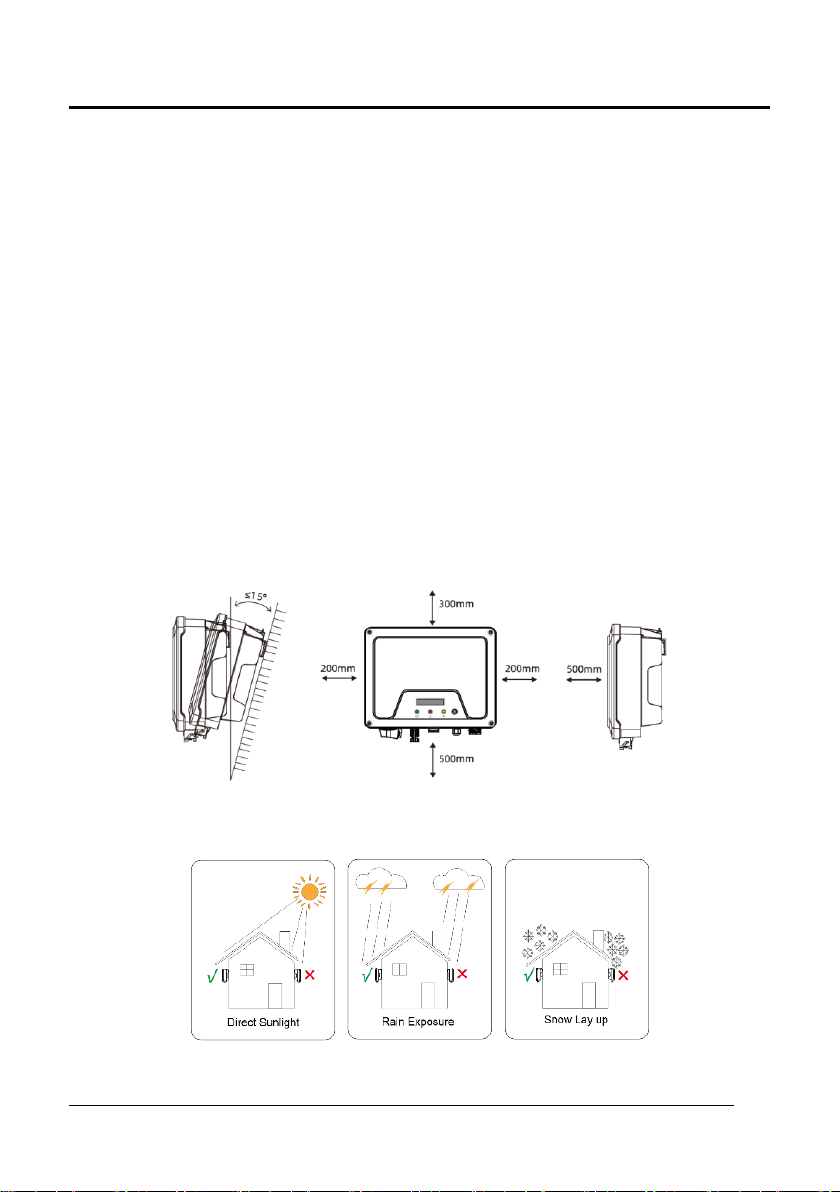
4.1 Installation Requirement ..................................................................................................8
4.2 Mounting Location ...........................................................................................................9
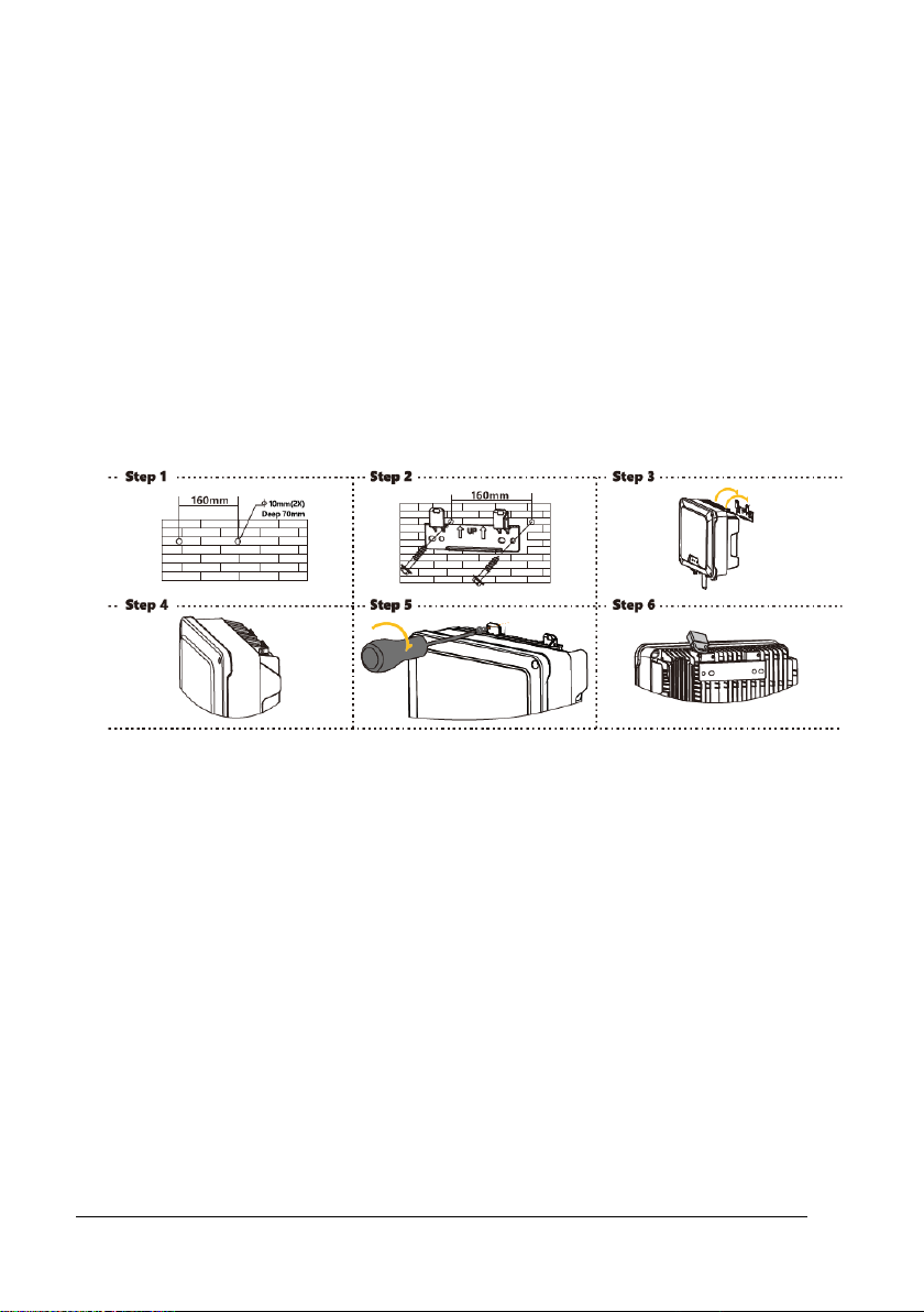
4.3 Mounting.........................................................................................................................10
4.4 Installing the PE cable ....................................................................................................10
4.5 Cable Specification .......................................................................................................11
5. COMMISSIONING.............................................................................................12
5.1 Safety Instructions ..........................................................................................................12
5.2 AC Wire Assembly and Connection ..............................................................................12
5.3 DC Wire Assembly and Connection ..............................................................................13
5.4 Residual Current Protection...........................................................................................14
6. COMMUNICATION ...........................................................................................15
6.1 System monitoring via Datalogger - RS485/Wi-Fi /GPRS (Optional) ........................15
6.2 Output Power Control via Smart Meter........................................................................16
6.3 Demand Responsive Modes(DRMs)........................................................................16
6.4 Auto Test (ONLY for Italian Market)..............................................................................17
7. START UP AND OPERATION...........................................................................19
7.1 Safety Check Before Start Up.........................................................................................19
7.2 Inverter LED Indicators ...................................................................................................20
7.3 Display and Control Logics ............................................................................................21
8. DISCONNECTING FROM VOLTAGE SOURCES .............................................22
9. TECHNICAL PARAMETERS...............................................................................23
10. TROUBLE SHOOTING ...................................................................................26
11. SYSTEM MAINTENANCE..............................................................................31
12. RESTARTS .......................................................................................................32

HPK-1000/1500/2000/2500/3000 USER MANUAL 4
1. SYMBOLS ON THE LABEL
DANGER, WARNING AND
CAUTION
RECYCLABLE AND REUSABLE
HIGH VOLTAGE
AVOID CONTACT
AVOID DAMP AND MOISTURE
HIGH TEMPERATURE
AVOID CONTACT
SHIPMENT STACK LIMIT: 10
CE MARKS
DO NOT DISPOSE WITH
HOUSEHOLD WASTE
PROCEED OPERATIONS
AFTER 5 MINUTES
DISCHARGE
BREAKABLE ITEM
PLACE UPWARDS
USER MANUAL IN PACK

5 HPS-1000/1500/2000/2500/3000 USER MANUAL
2. SAFETY AND WARNINGS
1. All persons who are responsible for mounting, installation, commissioning,
maintenance, tests, and service of HYPONTECH inverter products must be suitably
trained and qualified for corresponding operations. They MUST be experienced and
have knowledge of operation safety and professional methods. All installation
personnel must have knowledge of all applicable safety information, standards,
directives, and regulations.
2. The product must ONLY be connected and operated with PV arrays of protection
class II, in accordance with IEC 61730, application class A. The PV modules must also
be compatible with this product. Power resources other than compatible PV arrays
MUST not be connected and operate with the product.
3. When designing or constructing a PV system, all components MUST remain in their
permitted operating ranges, and their installation requirements MUST always be
fulfilled.
4. Under exposure to sunlight, the PV array may generate dangerous output in DC
voltage. Contacts with the DC wires, conductors and live components in the inverter
may result in lethal shocks.
5. High voltages in inverter could cause lethal electrical shocks. Before proceeding any
work, including maintenance and/or service, on the inverter, fully disconnect it from
all DC input, AC grid and other voltage sources. There MUST be a 5-minute waiting
time after the full disconnection.
6. The DC input voltage of the PV array MUST never exceed the maximum input
voltage of the inverter.
7. DO NOT touch parts of the inverter during operation as heat will be induced and
these parts will exceed 60℃.

HPK-1000/1500/2000/2500/3000 USER MANUAL 6
3. UNPACKING
3.1 Scope of Delivery
Please inspect and check for completeness in the scope of delivery. Confirm with
purchase order.
INVERTER
MOUNTING
BRACKET
MOUNTING
ACCESSORIES
DC PLUGS
(SEALED)
ACCONNECTOR
METER
CONNECTOR
COMMUNICATI
ON
DATALOGGER
(OPTIONAL)
DOCUMENTS
1
1
1
1pair
1
1
1
1
1) RS485/Wi-Fi/GPRS(optional)。
3.2 Product Overview
The total size of HPK-1000/1500/2000/2500/3000 is 297(width) ×223(height)
×117(depth) mm. It has 1 pairs of PV input terminals and 2 communication ports. It also
has a LCD&LED (or just LED, determined by user) for getting information and setting
parameters at field.
The detail description is shown below:

7 HPS-1000/1500/2000/2500/3000 USER MANUAL
Mark Num.
Component
Description
1
LCD&LED or LED
Display and setting device at field
2
DC Switch
For switch on/off the inverter
3
PV Terminal (s)
Connected with PV Panel
4
COM1: Wi-Fi/RS485/GPRS
Alternative distant communication method
5
COM2: METER
For smart-meter
6
AC Terminal
Connected with AC Grid
7
Secondary PE Terminal
For Grounding Protection

HPK-1000/1500/2000/2500/3000 USER MANUAL 8
4. INSTALLING
4.1 Installation Requirement
1. Please install the inverter(s) in places that can avoid inadvertent contact.
2. Installation method, location and surface must be fitting for the inverter’s weight and
dimensions.
3. Please install the inverter in an accessible location for operation, future maintenance
and service.
4. The inverter performance peaks at ambient temperature lower than 45℃.
5. When installing in residential or domestic environment, it is recommended to install
and mount the inverter on a solid, concrete wall surface. Mounting the inverter on
composite or plaster boards or walls with similar materials would induce noise during
its operation and is therefore not recommended.
6. DO NOT cover the inverter NOR place any objects on top of the inverter.
7. To ensure sufficient room for heat dissipation and maintenance, the clearing space
between inverter(s) and other surroundings is indicated below for reference:
8. Avoid direct exposure to sunlight and rain and snow layup.

9 HPS-1000/1500/2000/2500/3000 USER MANUAL
4.2 Mounting Location
1. DO NOT mount the inverter near any inflammable materials.
2. DO NOT mount the inverter near any explosive materials.
3. DO NOT mount the inverter on tilting surface over 15°backwards. Please mount the
inverter on a vertical wall surface.
4. DO NOT mount the inverter on any surfaces tilting forward or to either sides.
5. DO NOT mount the inverter on a horizontal surface.
6. For easy installation and operation, please mount the inverter on a height that the
display could match eye level.
7. The bottom side where all commissioning terminals are equipped MUST always point
downwards.

HPK-1000/1500/2000/2500/3000 USER MANUAL 10
4.3 Mounting
1. Use the mounting bracket as a template and mark the drill holes. Drill 2 holes using
a 10mm bit to 70mm depth.
2. Fix the mounting bracket with the screws and expansion bolts packed in mounting
accessories.
3. Attach the inverter to the mounting bracket.
4. Check both sides of the heat sink to ensure the inverter is stably attached.
5. Use M5 screws (T25 screwdriver, torque 2.5 Nm) to attach the heat sink fins to the
mounting bracket.
6. It is recommended to attach the anti-theft lock to the inverter. Lock diameter φ4-
5.5mm recommended.
4.4 Installing the PE cable
1. Insert the grounding conductor into the suitable terminal lug and crimp the contact.
2. Thread the M5 * 13 screw through the terminal lug.
3. Tighten it firmly into the housing (screwdriver type: T25, torque: 2.5Nm).

11 HPS-1000/1500/2000/2500/3000 USER MANUAL
Information on grounding components:
Object
Description
1
Housing
2
M5 terminal lug with protective conductor
3
M5×13 pan head screw
PE Conductor cross-section: 4-6 mm²
4.5 Cable Specification

HPK-1000/1500/2000/2500/3000 USER MANUAL 12
5. COMMISSIONING
5.1 Safety Instructions
1. Measure the frequency and voltage of grid connection and make sure they follow the
inverter’s grid connection specifications.
2. An external circuit-breaker on the AC side (or a fuse) at 1.25*AC rated current is
strongly recommended.
3. Reliability of all earth connections must be tested and valid.
4. Before commissioning, disconnect the inverter and the circuit-breaker or fuse, and
prevent accidental reconnection.
5.2 AC Wire Assembly and Connection
5.2.1 AC Commissioning
5.2.2 AC Switch Types
Please install an individual 2-stage miniature circuit breaker according to the following
specifications.
Model
Maximum output current(A)
AC Breaker Rated current(A)
HPK-1000
5
10
HPK-1500
7.5
16
HPK-2000
10
16
HPK-2500
12
20
HPK-3000
13.8
20

13 HPS-1000/1500/2000/2500/3000 USER MANUAL
5.3 DC Wire Assembly and Connection
1. PV modules of the connected strings must be of: the same time, identical alignment
and tilting angle.
2. Before commissioning and connecting the PV arrays, the DC switch MUST be open.
3. Parallel strings must have the same number of modules.
4. It is mandatory to use the DC connectors within package for the connection of PV
arrays.
5. The polarity of the PV arrays MUST be compatible to the DC connectors of the
inverter.
6. The DC input voltage AND DC input current of the PV array MUST never exceed the
maximum input allowance of the inverter.
DC Commissioning:
IF the DC port is MC4: Please follow the logics listed below.
IF the DC port is D4: Please follow the logics listed below.

HPK-1000/1500/2000/2500/3000 USER MANUAL 14
5.4 Residual Current Protection
This product is equipped with residual current protection device internally, in accordance
with IEC 60364-7-712. An external residual current protection device is not needed.
If the local regulation demands otherwise, it is recommended to install a 30mA Type B
residual current protection device.

15 HPS-1000/1500/2000/2500/3000 USER MANUAL
6. COMMUNICATION
6.1 System monitoring via Datalogger - RS485/Wi-Fi /GPRS (Optional)
6.1.1 Wi-Fi /GPRS Datalogger Installation
Unpack the Datalogger from package.
1. Unscrew the cap in COM1 port.
2. Plug the Datalogger in and tighten.
For user guidance and configuration of
Datalogger, please refer to the corresponding HYPONTECH Wi-Fi Stick Guide
manual, which is available in printed form inside Documents pack, or an online
manual on HYPONTECH website at .
6.1.2 RS485/Smart Meter Connection

HPK-1000/1500/2000/2500/3000 USER MANUAL 16
6.2 Output Power Control via Smart Meter
The inverter can control active power output via connecting smart meter, following is the
system connection mode.
Smart meter as above SDM230-Modbus connecting method and setting baud rate
method for Modbus please refer to its user manual.
6.3 Demand Responsive Modes(DRMs)
The demand response enabling device (DRED) may be connected to inverter via
HiManager, following is the system connection mode. For user guidance and
configuration, please refer to the《HiManager User manual》
DRMs Application Description
•Only applicable to AS/NZS4777.2:2015.
•DRM0, DRM5, DRM6, DRM7, DRM8 are available.

17 HPS-1000/1500/2000/2500/3000 USER MANUAL
For user guidance and configuration of HiManager, please refer to the corresponding
manual, available in Documents and HYPONTECH website.
The inverter shall detect and initiate a response to all supported demand response
commands , demand response modes are described as follows:
6.4 Auto Test (ONLY for Italian Market)
Auto-Test
1. The default setting of this function is disabled which can only be available in Italy
safety, Short press the button until first Line of LCD displays “Auto Test”, and long
press (>2s) the button to start this function. First line of LCD displays “Auto Testing”
and the second line of LCD displays “Start”. Release the button for more than 10s,
LCD will automatically switch to display the information about testing.
2. If auto test is finished, short press the button, Second line of LCD switches between
“Start” and “Result”. Under the “Result” display interface then release the button for
more than 10s, LCD will automatically switch to display the result of auto test. and
short press button to display test result one by one.
3. Auto test begin after the inverter relays close successfully. And LCD show the
information about testing. If sub test finishes and second line of LCD displays “Test
**** OK”, The first line of LCD displays voltage or frequency test value and the value

HPK-1000/1500/2000/2500/3000 USER MANUAL 18
of protection time. Inverter relay breaks off and reconnect to grid automatically
according to CEI 0-21 requirement, Then the next test starts. Test order is
81>.S1(maximum over frequency), 81>.S2(maximum over frequency),
81<.S1(minimum under frequency), 81<.S2(minimum under frequency),
59.S1(maximum voltage over 10min), 59.S2(maximum over voltage), 27.S1(minimum
under voltage), 27.S2(minimum under voltage).

19 HPS-1000/1500/2000/2500/3000 USER MANUAL
7. START UP AND OPERATION
7.1 Safety Check Before Start Up
Please check before switching on any voltage resources connected to the inverter and
closing inverter’s DC switch:
1. Grid Voltage: Check the grid voltage at point of connection at the inverter complies
with permitted range of the inverter.
2. Mounting Bracket: Check if the mounting bracket is properly and securely installed.
3. Mounting of the inverter: Check if the inverter is properly mounted and attached to
the mounting bracket.
4. DC Connectors: Check if the DC connectors are installed correctly on terminals.
5. AC Connectors and Wire Assembly: Check if wires are assembled correctly on the AC
side and if the AC connector is properly and securely installed. Check if the AC
connector is firmly plugged into AC terminal.
6. Cables: Check if all cables are reliably connected. Check if the connections are
effective, while the insulations are undamaged.
7. Groundings: Check all groundings using multimeter and if all exposed metal parts of
the inverter are properly grounded.
8. DC Voltage: Check if the largest open-circuit voltage of PV arrays complies with the
permitted range.
9. DC Polarity: Check if the wires from DC voltage resource are connected to terminals
with correct polarity.
10. Grounding Resistance: Check if the grounding resistance of PV strings >1MOhm using
a multimeter.
After all installation and checks, close the AC circuit-breaker, then the DC switch. The
inverter will start to operate when DC input voltage and grid conditions meet the
requirements of inverter startup.

HPK-1000/1500/2000/2500/3000 USER MANUAL 20
7.2 Inverter LED Indicators
When the inverter operates, LED symbols on display have the following meanings:
This manual suits for next models
9
Table of contents
Other Hypontech Inverter manuals