Cromtech TFF150HP Administrator Guide

CROMTECH™ FIRE FIGHTING PUMP
SINGLE IMPELLER
Thank you for your selection of a Cromtech Fire Fighting Pump
Single Impeller. This Operation Manual explains its use, installation,
checking and maintenance. We highly recommend that you retain
this manual for ready reference regarding its proper handling.
Spare Parts & Service
Phone: 1300 554 524
Freecall Fax: 1800 636 281
spareparts@crommelins.com.au
www.crommelins.com.au
Head Office (08) 9350 5588
OPERATION & INSTRUCTION MANUAL

2
Thank you very much for purchasing a Cromtech Fire Fighting Pump –Single Impeller
which can be used for domestic farming, fire fighting and general use. This manual covers
its operation and maintenance.
Please take a moment to familiarise yourself with the proper operation and maintenance
procedures in order to maximise the safe and efficient use of this product.
Keep this owner’s manual at hand, so that you can refer to it at anytime. Due to constant
efforts to improve our products, certain procedures and specifications are subject to
change without notice.
When ordering spare parts please have handy your products model number and serial
number. Record these numbers in the boxes below for future reference –the location of
these numbers vary depending on product.
CONTENTS
Introduction and Contents.................................................................................... 2
Safety….................................................................................................................. 3
Operating Instructions ....................................................................................... 4
Type of Water, Fixed Installation, Storage and Warranty.................................... 5
Specification Chart…............................................................................................. 6
Trouble Shooting Guide…...................................................................................... 7
Parts Diagram & List…........................................................................................... 8
SERIAL NO.
MODEL NO.

3
SAFETY
This manual contains important information on how to use the Cromtech Fire Fighting
Pump –Single Impeller model TFF150HP properly and safely. Please read through this
manual before you attempt to operate the machine.
This fire fighting pump is designed to give safe and dependable service if operated
according to the instructions.
•Always make a pre-operation inspection before starting the engine. (For more
information read the engine operational manual).
•Do not place flammable objects near the unit.
•Children and pets must keep away from the area of operation at all times.
•Never allow anyone to operate the unit without proper instructions.
•You must know how to stop the engine quickly and understand the operation of all
controls.
•Ensure the operating space is well ventilated. Avoid operating the machine in a closed
room, tunnel or other poorly ventilated places, as the exhaust fumes contain deadly
poisonous carbon monoxide. If the machine is unavoidably operated in such a place,
discharge the exhaust outside the room by a suitable means.
•Mufflers and other hot parts of the machine are dangerous. Do not touch them with
hands or any other body parts.
•Observe the following cautions when transporting. Close the fuel tank cap securely and
close the fuel tap tightly during transportation. Drain petrol from the fuel tank before
transporting over a long distance or on rough roads.
•Stop engine without fail before replenishing the fuel tank. Never replenish fuel while the
engine is running or remains hot otherwise spilled or evaporated fuel is liable to catch
fire from the engine spark or muffler heat. Wipe off spilled fuel before starting engine.
•To prevent injury, wear the following protective items: Wear ear plugs and any other
protective items required by job conditions.
COMPONENTS
Priming Cap
Non Return Valve
(Internal)
Inlet
Outlets (x3)
Drain Plug
Air Cleaner
Fuel Cap

4
OPERATING INSTRUCTIONS
Suction and discharge pipes:
To avoid air locks and make priming easy the suction pipe should be laid so that it rises
evenly from the water source to the pump. All pipe joints have to be sealed airtight and
they should be the same size or larger than the pump inlet and discharge outlet.
PRIMING
•To prime the pump, remove the priming plug and fill pump and suction pipe with water.
Pump has a non-return valve and is capable of drawing air from the normal size suction
pipes and hoses. Replace plug and start pump. If it pumps a small amount then stops,
turn it off, check the suction pipe for leaks and repeat the priming procedure until the
pump works well.
•When filled with water, self-priming pumps will gradually draw air from the suction line.
If priming a long or large diameter pipe, additional water may have to be added to the
pump at 3 minute intervals.
N.B. Do not run the pump dry of water for extended periods as it will destroy the
mechanical seal and void warranty.
HOW THE PUMP OPERATES
Before starting the pump, make sure the non-return valve is freely able to move. If the
pump fails to prime, there could be a problem with the suction pipe such as a leak, worn
impeller or too strong of a suction lift. Self-priming pumps will not self-prime with high
discharge head. If this is the case, the suction flap valve should be removed and a suction
foot valve installed on the hose.
SUCTION STRAINER
A suction hose strainer may be needed for portable pump use. This stops gravel or any large
debris getting into the pump and causing damage.
ENGINE
Engine user manual is enclosed. Using low speed extends the life of your engine. When
continually pumping, we recommend operation at approximately 3000rpm. In contrast,
high speed will increase the pump’s performance when needed as in fire fighting or intense
situations. However, be aware that pump life will eventually suffer if high speed is
continually applied.

5
TYPE OF WATER
If any liquid contains stringy or large material that may cause obstruction, a suction
strainer should be used. If the pump is needed for chemicals, you must check the pump
compatibility with your local dealer.
FIXED INSTALLATIONS
In some installations and only if the pump is used under stressful conditions, such as
pumping uphill for long distances, the pump may not work on start up.
To rectify this, a check valve should be installed between the pump and the pipe and a
gate valve should be installed on the pump discharge. If it still fails, open the valve to
release a full flow of water and close it again. It should now pump fully. Under some
conditions the procedure might have to be repeated at each start up.
STORAGE
•Make sure that the engine is completely cooled off before storage.
•Clean up oil and dust accumulation on rubber parts.
•Drain pump completely of all water.
•Cover the machine and store it in a dry place.
•For long-term storage of this petrol unit, remove fuel from the fuel tank. Also remove
fuel remaining in the fuel line and chamber of the carburettor. To drain fuel from the
chamber of the carburettor, remove the drain plug provided at the chamber and drain
the fuel.
WARRANTY
Consult the Crommelins Machinery Warranty Information leaflet, supplied with your new
product, for details of your machinery warranty including consumer advice and
information about accessing a service agent to repair your product. You can also visit our
website at www.crommelins.com.au to find your local service agent who will be able to
assist with all warranty claims.

6
FIRE FIGHTING PUMP –SINGLE IMPRELLER SPECIFICATION CHART
MODEL
TFF150HP
Inlet (inch)
1 ½”
Outlet (inch)
1 x 1 ½”& 2 x 1”
Total Head (m)
60m
Volume max. (L/min)
360L/min
Volume max. (L/hr)
21,600L/HR
Max. Suction lift (m)
8m
Pump Type
Aluminium
Suction Type
Self-priming
Impeller
Single
Axle Seal Material
Ceramic-carbon
Engine Make
Honda
Engine Type
GP160
Starting System
Recoil Start
Fuel Type
Petrol
Fuel Tank (L)
3.6L
Noise Level (db@7m)
70db
Weight (kg)
25kg
Manufacturers Warranty
1 year
Engine Warranty
1 year

7
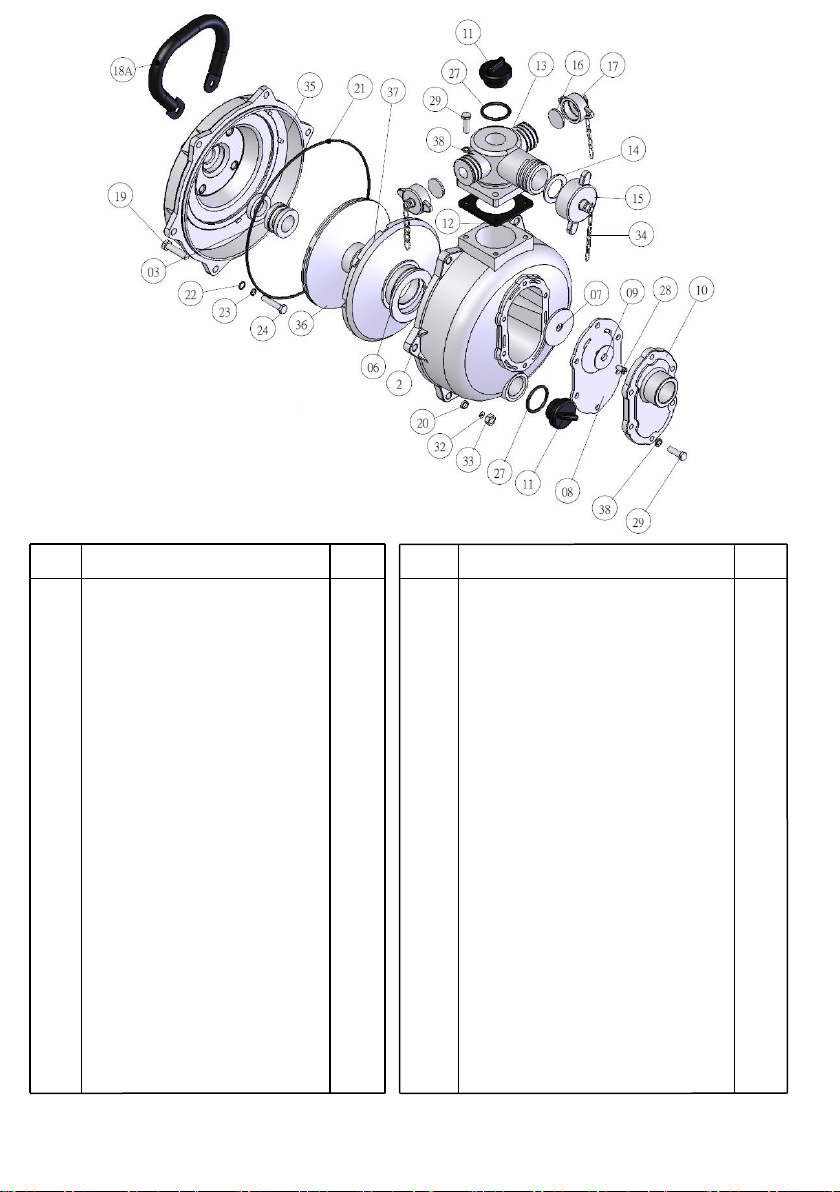
PARTS DIAGRAM AND LIST
TROUBLE SHOOTING GUIDE
PROBLEM
CAUSE
SOLUTION
Engine won’t start
1. Engine switch in OFF
position
2. No fuel in engine
3. Worn, fouled or dirty
spark plug
4. Engine not level or
engine oil level too
low
1. Turn engine switch to ON
position
2. Fill fuel tank or turn on fuel
supply
3. Replace with factory
recommended spark plug
4. Place engine on level surface
or fill crankcase with oil (refer
to engine manufacturers
instruction manual)
Engine with low power
1. Throttle control lever
not set to full throttle
position
1. Set throttle control lever to
full position
Engine runs rough
1. Dirty air filter
2. Out of petrol
3. Stale petrol
4. Spark plug wire not
connected to spark
plug
1. Clean or replace air cleaner
2. Fill fuel tank
3. Drain fuel tank, fill with fresh
fuel
4. Connect wire to spark plug
Pump will not prime
within 30 seconds
1. Air leak on suction
side
2. Blocked impeller
3. Pump too far away
from water level
1. Check couplings/hoses
2. Clear blockage
3. Lower pump to within 8
metres of water level
8
No. Description Qty No. Description Qty
02 Casing Outer (Ali Alloy) 1 22 O’Ring 7x11 4
03 Seal Assembly 1 23 Washer (Stainless) 5/16” 4
06 Seal Ring, Volute 1 24 Set Screw, UNF 5/16”x 1 ½ “ 4
07 Flap Valve Weight 1 (Stainless)
08 Flap Valve Rubber 1 27 O’Ring 31.5 x 39.5 2
09 Flat Valve Washer 1 28 Screw ¼ “ x ½ “ 1
10 Cover, Suction (Inlet 1 ½ “) 1 29 Set Screw 5/16” x 1” 9
11 Priming & Drain Plug (Cap) 2 32 Washer, Inside Ratchet 3/8”x17 6
12 Gasket, Discharge Bend 1 33 Nut, UNF 3/8” 6
13 Discharge Tee (Outlet 1 ½ “) 1 34 Chain 3
14 Rubber Gasket 1 35 Casing Inner (Aluminium Alloy) 1
15 Butterfly Nut (1 ½ “) 1 36 Impeller, Close (H) Type 1
16 Rubber Gasket (1”) 2 37 Diffuser (H) 1
17 Butterfly Nut (1”) 2 38 Washer 5/16” 11
18A Handle 1 41 Foot 5/16” 2
19 Set Screw, UNF 3/8”x 1 ½ “ 6 41-1 Nut, UNF 5/16” 2
20 Washer 3/8 6 41-3 Spring Washer 2
21 O’Ring 241x247 1 51 Shaft Sleeve 1
Table of contents
Other Cromtech Water Pump manuals


Popular Water Pump manuals by other brands


Oase
Oase AquaMax Eco Premium 6000/12 V manual

Grundfos
Grundfos Hydro Multi-B instructions

EBARA
EBARA WINNER Operating and maintenance manual

Tuthill
Tuthill KINNEY DRSP Installation and operation manual

Intex
Intex Quick-Fill Operation instructions

BRINKMANN PUMPS
BRINKMANN PUMPS SXC2824-R operating instructions


