Cronyx FMUX/SAT User manual

© 2006 Cronyx
Multiplexer
FMUX/SAT
4 x E1 ports
V.35/RS-530/RS-449 link interface
in codirectional mode
Installation and Operations
Manual
Document version: 1.7E / 06.09.2006

2FMUX/SAT Multiplexer
© 2006 Cronyx
Safety Precautions
An exclamation point enclosed in a triangle warns the user about important
operations and maintenance instructions for the device.
It is mandatory to observe the existing safety rules during installation, operation,
and maintenance of the device. Installation, maintenance, and repair operations must
be performed only by qualied and certied personnel. Installation, maintenance,
and repair operations may not be performed by the operator or the user.
This is to certify that the multiplexer equipment «FMUX» manufactured by
«Cronyx» in compliance with Technical Specifications 150.RUS ТУ is compliant
with the following requirements:
• «Technical Requirements to secondary time trunking equipment for 2/8 Mbit/s
digital transmission systems» approved by the Ministry of Information Tech-
nologies and Communications of the Russian Federation, January 17, 1997;
• «Technical Requirements to tertiary time trunking equipment for 2/34 Mbit/s
digital transmission systems» approved by the Ministry of Information Tech-
nologies and Communications of the Russian Federation, January 17, 1997.
Multiplexer equipment «FMUX» has the following application conditions: in pub-
lic network as secondary and tertiary time trunking equipment of plesiochronous
digital hierarchy.

© 2006 Cronyx
3
Firmware Version
This manual applies to the device with the following rmware version:
Order code prex Firmware version
FMUX/S - 4E1 - SAT Revision A, 28/04/2006
The unit is manufactured in the “/S” design, as a device in 1U high metal enclosure,
for mounting in a 19” rack.
Device specications and design may be changed without prior notice to consumers.

4FMUX/SAT Multiplexer
© 2006 Cronyx
Contents
Section 1. Introduction....................................................6
1.1. Purpose ..................................................................................................... 6
1.2. Features .................................................................................................... 6
1.3. Order Code ............................................................................................... 7
1.4. Connection Diagram ................................................................................ 8
1.5. Specications ........................................................................................... 9
E1 Ports .................................................................................................... 9
Link Port .................................................................................................. 9
Console Port ............................................................................................. 9
SNMP Management Port ....................................................................... 10
Emergency Alarm Port........................................................................... 10
Diagnostic Modes .................................................................................. 10
Dimensions and Weight ......................................................................... 10
Power Supply ......................................................................................... 10
Operating Conditions ............................................................................. 10
Section 2. Installation....................................................11
2.1. Installation Space Requirements .............................................................11
2.2. Delivered Items .......................................................................................11
2.3. Cable Connections ..................................................................................11
Power Supply Connector ....................................................................... 12
Grounding .............................................................................................. 12
E1 Port Connectors ................................................................................ 12
Link Port Connector (V.35, RS-530, RS-449) ....................................... 13
Cable Diagrams for Connections to Link Port ...................................... 14
V.35 Cable for Connection to DCE ............................................... 14
V.35 Cable for Connection to DTE ................................................ 14
RS-530 Cable for Connection to DСE .......................................... 15
RS-530 Cable for Connection to DTE ........................................... 15
RS-449 Cable for Connection to DCE .......................................... 16
RS-449 Cable for Connection to DTE ........................................... 16
SNMP Port Connector ........................................................................... 17
Console Port Connector ......................................................................... 17
Emergency Alarm Connector ................................................................. 18

© 2006 Cronyx
5
Contents
Section 3. Operation..................................................... 19
3.1. Indicators ................................................................................................ 19
3.2. Alarms .................................................................................................... 21
3.3. Device Response to Emergencies .......................................................... 22
3.4. Loops ...................................................................................................... 23
Port Loop ............................................................................................... 23
Tributary Loop ....................................................................................... 23
Local Link Loop .................................................................................... 24
Remote Link Loop ................................................................................. 24
3.5. Built-in BER Tester ................................................................................ 25
Link Testing Via Remote Loop .............................................................. 26
Enabling BER testers in Opposite Directions ........................................ 26
Section 4. Management over Console Port................ 27
4.1. Upper Level Menu ................................................................................. 27
4.2. Menu Structure ....................................................................................... 29
4.3. "Link statistics" Menu ............................................................................ 30
4.4. "E1 port ptatistics" Menu ....................................................................... 31
4.5. "Event counters" Command ................................................................... 32
4.6. "Loop" Menu .......................................................................................... 33
"Port loop" Menu ................................................................................... 34
"Tributary loop" Menu ........................................................................... 34
4.7. "Test" Menu ........................................................................................... 35
4.8. "Congure" Menu .................................................................................. 36
"Port conguration" Menu ..................................................................... 36
"Link" Menu .......................................................................................... 37
"SNMP" Menu ....................................................................................... 38
"Sensor input" Command ...................................................................... 39
"Factory settings" Command ................................................................. 39
"Save parameters" Command ................................................................ 39
"Restore parameters" Command ............................................................ 39
4.9. "Login to remote device" Command ..................................................... 40
4.10. "Reset" Command ................................................................................ 40
Section 5. Management over SNMP............................ 41
5.1. Conguring SNMP Parameters .............................................................. 41
5.2. Management Information Blocks (MIBs) .............................................. 42

6FMUX/SAT Multiplexer
© 2006 Cronyx
Section 1. Introduction
1.1. Purpose
FMUX/SAT is a multiplexer with variable frame structure, which allows transmitting up
to four E1 channels over synchronous link equipment with codirectional interface, such
as satellite modem with V.35 DCE interface (see Section "1.3. Connection Diagram").
Note
Hereinafter term "E1" is used to denote data transmission channel with interface
complying with ITU-T G.703 standard for transmitting data with bit rate of 2,048
kbit/s in both framed mode in accordance with ITU-T G.704 standard, and unframed
(transparent) mode.
1.2. Features
•Data transmission from one to four E1 ports over synchronous link equipment
with codirectional interface. Link bit rate depends on the number of Е1 ports used:
Number
of Е1 Ports
Link
Bit Rate,
Mbit/s
48.448
36.336
24.224
12.112
•Support of ITU-T G.703 standard for 2,048 kbit/s, in both framed mode in accordance
with ITU-T G.704 standard, and unframed (transparent) mode
•Compliance with ITU-T G.703, G.823 standards
•Local and remote loops
•Built-in Bit Error Rate tester (BER tester)
•RS-232 console port for monitoring and control
•Auxiliary Ethernet 10Base-T port for management via SNMP
•Remote management
•Emergency alarms ("dry contacts")
•1U high unit design for a 19" rack

© 2006 Cronyx
7
Section 1. Introduction
•Built-in power supply unit for mains or battery
E1 port data are transmitted independently, the clock frequency of each port does not
depend on that of the other ports.
The device may be managed over the RS-232 interface using ASCII terminal (console),
or over SNMP protocol over auxiliary Ethernet 10BaseT port.
Loop and built-in BER tester management is performed from the console. BER tester
allows measuring error rate in the link path. The measurements are performed using
xed or pseudo-random code in accordance with ITU-T О.151 standard (the pattern
length is 215 - 1 = 32,767 bits).
A remote login ability is provided for testing remote device ports from local console,
when there is no personnel at the other end of the link. Commands to remote device are
sent over monitoring channel, organized in the link path.
The FMUX/SAT is equipped with LED indicators, which show state of ports and link
equipment, loops enabled states, and testing modes.
The device is equipped with an emergency alarm relay, the "dry" contacts of which may
switch on external device to call the operations personnel (in accordance with ITU-T
G.742 Standard, s. 10).
The multiplexer has capability of rmware upgrades.
1.3. Order Code
e FMUX/SAT multiplexer is manufactured as a device in 1U high metal enclosure, for
mounting in a 19” rack.e multiplexer is equipped with auxiliary Ethernet 10Base-T
port for management over SNMP protocol.
e power supply device for 176 - 264 VAC mains has the following order code:
FMUX/S – 4E1 – SAT – SNMP – AC
e device may be ordered with 36 – 72 VDC power supply. In this case "– AC" sux
in the order code must be replaced with "– DC".
8FMUX/SAT Multiplexer
© 2006 Cronyx
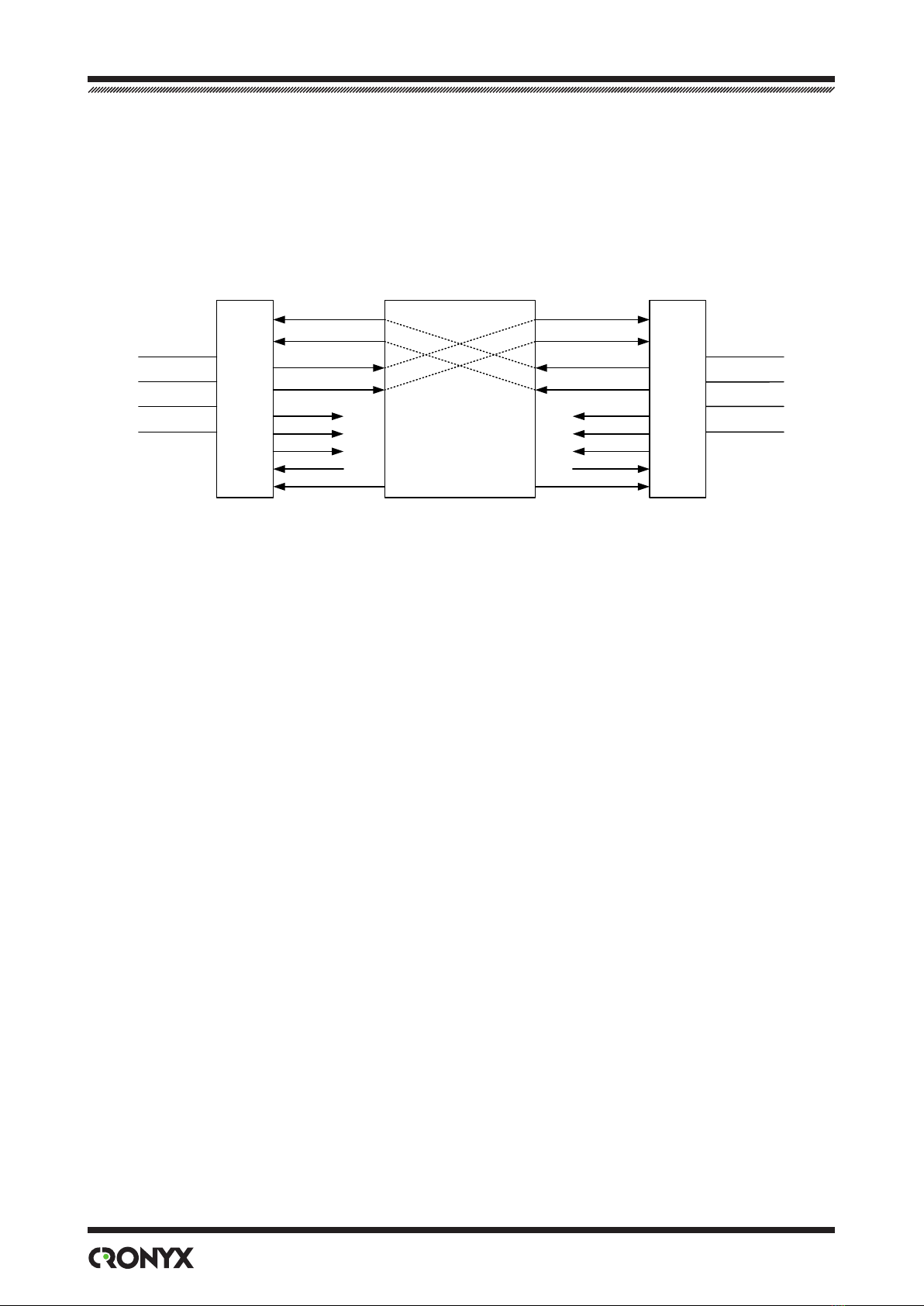
1.4. Connection Diagram
General diagram for connecting FMUX/SAT multiplexers to data transmission equip-
ment may be presented as follows:
E1 port
E1 port
Data
transmission
equipment
TXD-a,b
ETC-a,b
RTS
RXD-a,b
RXC-a,b
CD
DSR
CTS
DTR
E1 port
E1 port
TXD-a,b
ETC-a,b
RTS
RXD-a,b
RXC-a,b
CD
DSR
CTS
DTR
E1 port
E1 port
E1 port
E1 port
FMUX/SAT
FMUX/SAT
Fig. 1. Diagram for connecting FMUX/SAT multiplexer
to data transmission equipment
Multiplexed data from E1 ports are transmitted over group link via data transmission
equipment, and are demultiplexed at the opposite side. Positive digital justication is
used for frequency recovery in each separate E1 link.
An example of data transmission equipment may be satellite link and pair of satellite
modems operating in codirectional mode ("codirectional" principle suggests that data
and corresponding clock signal are transmitted at the same direction). In this case RXD
signal and RXC clock signal are transmitted from one multiplexer, and received as TXD
and ETC by another multiplexer.
The RXC signal is generated on basis of transmitting multiplexer internal clock, and is
used for synchronization during group link data reception by receiving multiplexer. It
is important that data transmission equipment should transmit this signal to ETC input
of receiving multiplexer transparently.
The FMUX/SAT multiplexer is DCE, and supports operation with CD, DSR, CTS, DTR,
and RTS modem signals.
The multiplexer uses the RTS signal loss for indicating the non-operating state of data
transmission equipment (in this case "LOS" indicator on the multiplexer lights).
The DTR does not affect operations of the device, but its state is shown on console.

© 2006 Cronyx
9
Section 1. Introduction
1.5. Specications
E1 Ports
Nominal bit rate ............................................................. 2,048 kbit/s
Encoding ........................................................................ HDB3
Frame structure .............................................................. Transparent G.703 stream
transmission in both framed
(G.704), and unframed mode
Error control ................................................................... Code violations
Link impedance .............................................................. 120 Ohm balanced (twisted
pair)
Receiver signal level ...................................................... 0 to -12 dB
Jitter attenuation ............................................................. In the transmit path
Overvoltage protection ................................................... TVS
Overcurrent protection ................................................... Fuse
Connector ...................................................................... RJ-48 (female, 8 pin)
Link Port
Interface type ................................................................. Multistandard (V.35, RS-530,
RS-449); in the codirectional
mode
Clock frequency ............................................................. 8.448, 6.336, 4.224 or
2.112 MHz ± 30 ppm
Modem signals ............................................................... TXD, ETC, RXD, RXC, CD,
DSR, CTS, RTS
Connector ....................................................................... HDB44 (female)
Console Port
Interface type ................................................................. RS-232 DCE
Data transmission protocol ............................................ Asynchronous, 9600 bit/s, 8
bits/character, 1 stop bit, no
parity
Modem signals ............................................................... DTR, DSR, CTS, RTS, CD
Connector ....................................................................... DB-9 (female)

10 FMUX/SAT Multiplexer
© 2006 Cronyx
SNMP Management Port
Interface type ................................................................. Ethernet 10Base-T
Connector ....................................................................... RJ-45
Emergency Alarm Port
Connector ....................................................................... DB-9 (male)
Relay contacts current .................................................... Up to 600 mA
Relay contacts voltage ................................................... Up to 110 VDC; up to
125 VAC
Diagnostic Modes
Loops.............................................................................. Local, remote
BER tester ...................................................................... Built-in
Management ................................................................... Over RS-232 control port
(console), over SNMP, or
from remote device
Dimensions and Weight
Dimensions .................................................................... 444 mm × 262 mm × 44 mm
Weight ............................................................................ 3,400 grams
Power Supply
From AC mains ("-AC" option) ..................................... 176 – 264 VAC, 50 Hz
From DC source ("-DC" option) .................................... 36 – 72 VDC
Power consumption ........................................................ No more than 20 W
Operating Conditions
Temperature ................................................................... 0 to +50 °C
Relative humidity ........................................................... Up to 80 %, non-condensing

© 2006 Cronyx
11
Section 2. Installation
Section 2. Installation
2.1. Installation Space Requirements
When installing the multiplexer, allow for at least 10 cm of free space at the front of
device for interface cable connections.
e ambient temperature must be 0 to +50 °С, with humidity of up to 80 %, non-con-
densing.
2.2. Delivered Items
e FMUX unit of the corresponding design ......................................................1 pc.
Bracket for mounting FMUX unit in 19" rack .....................................................2 pcs.
Self-adhesive foot for FMUX unit..........................................................................4 pcs.
Power supply cable (for "-AC" model)....................................................................1 pc.
Removable part of power supply connector terminal unit (for "-DC" model) .1 pc.
Installation and Operations Manual......................................................................1 pc.
2.3. Cable Connections
All connectors are located on the front panel of multiplexer:
LERR LOS
RERR TST
PWR
SNMP CONSOLE ALARM
0 1 2 3
Alarm
Console
E1 ports
Power
Ground
SNMP port
Link port
(V.35/RS-530/RS-449)
PORT
FMUX
Fig. 2. Connector locations

12 FMUX/SAT Multiplexer
© 2006 Cronyx
Power Supply Connector
Standard mains connector (IEC 320 C14) is used to connect AC power supply cable (for
“-AC” model). e power supply cable is supplied with the device.
To connect DC power supply cable (for “-DC” model), the power supply connector's
terminal unit is used. e connector’s pin assignment shown below (view from device's
front panel side):
Fig. 3. DC power supply connector
e corresponding removable part of terminal unit of the power supply connector, is
supplied with the device.
Grounding
M4 screw is located on the front panel for device grounding.
Before switching device on, and before connecting other cables, the device
must be properly grounded.
E1 Port Connectors
RJ-48 connector is used for E1 port connections:
Fig. 4. E1 port connector

© 2006 Cronyx
13
Section 2. Installation
Link Port Connector (V.35, RS-530, RS-449)
HDB44 (female) connector is used for connecting link port:
Fig. 5. Link port connector
Pin V.35 RS-530, RS-449
10 TXD-a TXD-a
25 TXD-b TXD-b
8 RXD-a RXD-a
9 RXD-b RXD-b
6 ETC-a ETC-a
7 ETC-b ETC-b
5 RXC-a RXC-a
4 RXC-b RXC-b
14 RTS RTS-a
29 — RTS-b
11 DTR DTR-a
26 — DTR-b
13 DSR DSR-a
28 — DSR-b
15 CTS CTS-a
30 — CTS-b
12 CD CD-a
27 — CD-b
1,16 GND GND
31 SEL-0* SEL-0*
33 SEL-1 SEL-1*
35 SEL-2 SEL-2
37 SEL-3 SEL-3*
39 SEL-4* SEL-4
41 SEL-5* SEL-5
43 SEL-6* SEL-6
* - Connect contact to GND

14 FMUX/SAT Multiplexer
© 2006 Cronyx
Cable Diagrams for Connections to Link Port
Below are cable diagrams for connecting to DTE and DCE devices using external transmit
clock. Multiplexer V.35 port input signals are denoted by left arrow ("←"), and output
signals are denoted by right arrow ("→").
V.35 Cable for Connection to DCE V.35 Cable for Connection to DTE
Signal HDB44
(male)
M34
(male)
Signal
TXD-a 10 ←R RXD-a
TXD-b 25 ←T RXD-b
RXD-a 8 →P TXD-a
RXD-b 9 →S TXD-b
ETC-a 6 ←V RXC-a
ETC-b 7 ←X RXC-b
RXC-a 5 →U ETC-a
RXC-b 4 →W ETC-b
RTS 14 ←F CD
DTR 11 ←E DSR
DSR 13 →H DTR
CD 12 →C RTS
CTS 15 Not connected
GND 1 ↔A GND
GND 16 ↔B GND
SEL-x Connect
31, 32, 39,
41, 43 to
GND 1
Signal HDB44
(male)
M34
(female)
Signal
TXD-a 10 ←P TXD-a
TXD-b 25 ←S TXD-b
RXD-a 8 →R RXD-a
RXD-b 9 →T RXD-b
ETC-a 6 ←U ETC-a
ETC-b 7 ←W ETC-b
RXC-a 5 →V RXC-a
RXC-b 4 →X RXC-b
RTS 14 ←C RTS
DTR 11 ←H DTR
DSR 13 →E DSR
CTS 15 →D CTS
CD 12 →F CD
GND 1 ↔A GND
GND 16 ↔B GND
SEL-x Connect
31, 39,
41, 43 to
GND 1

© 2006 Cronyx
15
Section 2. Installation
RS-530 Cable for Connection to
DСE
Signal HDB44
(male)
DB25
(male)
Signal
TXD-a 10 ←3 RXD-a
TXD-b 25 ←16 RXD-b
RXD-a 8 →2 TXD-a
RXD-b 9 →14 TXD-b
ETC-a 6 ←17 RXC-a
ETC-b 7 ←9 RXC-b
RXC-a 5 →24 ETC-a
RXC-b 4 →11 ETC-b
RTS-a 14 ←8 CD-a
RTS-b 29 ←10 CD-b
DTR-a 11 ←6 DSR-a
DTR-b 26 ←22 DSR-b
DSR-a 13 →20 DTR-a
DSR-b 28 →23 DTR-b
CTS-a 15 Not connected
CTS-b 30 Not connected
CD-a 12 →4 RTS-a
CD-b 27 →19 RTS-b
GND 1 ↔1
GND 16 ↔7
SEL-x Connect
31, 32,
33, 37 to
GND 1
RS-530 Cable for Connection to
DTE
Signal HDB44
(male)
DB25
(female)
Signal
TXD-a 10 ←2 TXD-a
TXD-b 25 ←14 TXD-b
RXD-a 8 →3 RXD-a
RXD-b 9 →16 RXD-b
ETC-a 6 ←24 ETC-a
ETC-b 7 ←11 ETC-b
RXC-a 5 →17 RXC-a
RXC-b 4 →9 RXC-b
RTS-a 14 ←4 RTS-a
RTS-b 29 ←19 RTS-b
DTR-a 11 ←20 DTR-a
DTR-b 26 ←23 DTR-b
DSR-a 13 →6 DSR-a
DSR-b 28 →22 DSR-b
CTS-a 15 →5 CTS-a
CTS-b 30 →13 CTS-b
CD-a 12 →8 CD-a
CD-b 27 →10 CD-b
GND 1 ↔1 GND
GND 16 ↔7 GND
SEL-x Connect
31, 33,
37 to
GND 1

16 FMUX/SAT Multiplexer
© 2006 Cronyx
RS-449 Cable for Connection to
DTE
Signal HDB44
(male)
DB37
(female)
Signal
TXD-a 10 ←4 TXD-a
TXD-b 25 ←22 TXD-b
RXD-a 8 →6 RXD-a
RXD-b 9 →24 RXD-b
ETC-a 6 ←17 ETC-a
ETC-b 7 ←35 ETC-b
RXC-a 5 →8 RXC-a
RXC-b 4 →26 RXC-b
RTS-a 14 ←7 RTS-a
RTS-b 29 ←25 RTS-b
DTR-a 11 ←12 DTR-a
DTR-b 26 ←30 DTR-b
DSR-a 13 →11 DSR-a
DSR-b 28 →29 DSR-b
CTS-a 15 →9 CTS-a
CTS-b 30 →27 CTS-b
CD-a 12 →13 CD-a
CD-b 27 →31 CD-b
GND 1 ↔1 GND
GND 16 ↔19 GND
SEL-x Connect
31, 33,
37 to
GND 1
RS-449 Cable for Connection to
DCE
Signal HDB44
(male)
DB37
(female)
Signal
TXD-a 10 ←6 RXD-a
TXD-b 25 ←24 RXD-b
RXD-a 8 →4 TXD-a
RXD-b 9 →22 TXD-b
ETC-a 6 ←8 RXC-a
ETC-b 7 ←26 RXC-b
RXC-a 5 →17 ETC-a
RXC-b 4 →35 ETC-b
RTS-a 14 ←13 CD-a
RTS-b 29 ←31 CD-b
DTR-a 11 ←11 DSR-a
DTR-b 26 ←29 DSR-b
DSR-a 13 →12 DTR-a
DSR-b 28 →30 DTR-b
CTS-a 15 Not connected
CTS-b 30 Not connected
CD-a 12 →7 RTS-a
CD-b 27 →25 RTS-b
GND 1 ↔1 GND
GND 16 ↔19 GND
SEL-x Connect
31, 32,
33, 37 to
GND 1

© 2006 Cronyx
17
Section 2. Installation
SNMP Port Connector
RJ-45 female socket is used for connection of Ethernet cable (10Base-T, IEEE 802.3
standard) for management via SNMP protocol:
Fig. 6. SNMP port connector
Use direct cable for connection to hub.
Console Port Connector
e device may be managed using ASCII terminal (console). DB-9 (female) connector
is used for console connection. e console port has standard RS-232 DCE interface,
and utilizes the following settings: asynchronous mode, 9600 Baud speed, 8 bits/symbol,
1 stop bit, no parity.
An RTS signal (for ow control) from the console terminal is required for
proper operation.
It is recommended to use following cable diagrams:
Cable without modem control
GND 5
TXD 3
RXD 2
RTS 7
CTS 8
DTR 4
CD 1
GND
TXD
RXD
RTS
CTS
DTR
DSR
CD
GND 5
TXD 3
RXD 2
RTS 7
CTS 8
DTR 4
DSR 6
CD 1
GND
TXD
RXD
RTS
CTS
DTR
DSR
CD
Cable with modem control
Fig. 7. Console cable diagrams
Use direct cable for connection to PC COM port.

18 FMUX/SAT Multiplexer
© 2006 Cronyx
Emergency Alarm Connector
DB-9 (male) connector is used for emergency alarm connection:
Pin-out:
1–open during no alarm, closed to the middle relay contact
(6) during alarm
2–closed to the middle relay contact (6) during no alarm,
open during alarm
3 – pin for external input sensor connection
6 – middle relay contact
7, 8 – common (GND)
4, 5, 9 – reserved (must not be used)
Alarm relay
(shown when no alarm present)
External input sensor
1 2 3 4 5
7 86 9
+5 V
Internal device circuits
Connector pin-out:
view from outside of the device
Fig. 8. Emergency alarm connector
External input sensor connected to the device must be isolated from other
electrical circuits. Failure to comply with this requirement may lead to device
malfunction.

© 2006 Cronyx
19
Section 3. Operation
Section 3. Operation
3.1. Indicators
e front panel contains indicators, showing device status. List of the indicators and
their functions are presented in the table.
LERR LOS
RERR TST
SNMP CONSOLE ALARM
PWR
FMUX
LERR LOS PORT LOS PORT STATE SNMP EACT SNMP ELINK
PWR RERR TST
0 1 2 3
PORT
Fig. 9. Indicator locations
Indicator Color Description
LERR Red Link port errors:
•lights or ashes during high error rate in the link port
input signal;
•lights when receiving test pattern from the link port
with loop enabled on the link;
•lights or ashes when there are BER tester errors in
the link test mode (TST indicator lights).
LOS Red Lights during loss of the RTS signal.
PORT LOS Red E1 port errors:
•ashes during HDB3 coding errors in the correspond-
ing E1 port;
•lights during loss of carrier in corresponding E1
port;
•lights when receiving AIS signal at the input of cor-
responding E1 port.

20 FMUX/SAT Multiplexer
© 2006 Cronyx
Indicator Color Description
PORT STATE Green E1 port operating mode:
•lights – normal operation;
• does not light – port is not used;
• ashes – loop enabled on the port;
• double ashes – tributary loop enabled on the port.
PWR Green Power is supplied to the device.
RERR Red Errors of remote device (when RTS signal is present
on the link port input of local device):
•loss of RTS signal at the link port input of remote
device;
•loss of link port synchronization of remote device.
TST Red Test mode:
•ashes when BER tester is enabled towards the link
port;
•ashes when loop is enabled on the link port;
• double ashes when remote loop is enabled.
SNMP EACT Green Ethernet data transmission in progress
SNMP ELINK Green Ethernet 10Base-T cable connected
In the normal mode indicators must be in the following states:
Indicator Color Normal state
PWR Green Lights
LERR Red Does not light
LOS Red Does not light
RERR Red Does not light
TST Red Does not light
PORT LOS Red Does not light
PORT STATE Green Lights if port is used
SNMP EACT Green Flashes during Ethernet data transmission
SNMP ELINK Green Lights if Ethernet 10Base-T cable is connected
Table of contents
Other Cronyx Multiplexer manuals


Popular Multiplexer manuals by other brands

Microsemi
Microsemi PDS-EM-8100 Quick Installation and Initial Configuration

ShipModul
ShipModul MiniPlex-2USB NMEA-0183 manual

Paradyne
Paradyne Hotwire 8776 installation instructions

Patton electronics
Patton electronics 1195/8E1 quick start guide

Agilent Technologies
Agilent Technologies E1343A Service manual

Siqura
Siqura CCM 1010 user manual

Dolby Laboratories
Dolby Laboratories MPX500 user manual

VISTEK
VISTEK V1634A Installation and operation

Actisense
Actisense PRO-NDC-1E user manual

Leitch
Leitch Neo AS-3901-B Installation and operation manual

artisan
artisan pickering 20-740 Series user manual

Comnet
Comnet FVT Installation and operation manual


