IMPORTANT NOTE
Instruments are delivered ready for immediate use; no extras are required.
Supplied Accessories:
1 Set of test leads
1 Mains cord
1 Operating Instructions (English)
When unpacked, inspect for physical damage and report any defects immediately in writing,
retaining packaging materials for inspection. Before placing into service, ensure mains voltage
is correct, instruments are normally supplied for 230V 50Hz. Other voltages may also be
selected according to the chart in section 5, (Maintenance). Be sure to also change the fuse to
the correct type.
1. SAFETY
This apparatus is designated Safety Class I as defined in the IEC Publication 1010-1 (Amend 1)
This apparatus has been designed and tested in accordance with IEC Publication 348, entitled
“Safety Requirements for Electronic Measuring Apparatus”, and has been supplied in a safe
condition. The present instruction manual contains some information and warnings, which
must be followed by the user to ensure safe operation and to retain the apparatus in safe
condition.
This instrument has been designed and tested to BS EN:61010 overvoltage category CAT III <50V
Before switching on the apparatus, make sure that it is set to the voltage of the power supply.
The mains plug shall only be inserted in a socket outlet provided with protective earth contact.
The protective action must not be negated by the use of an extension lead without a protective
conductor.
WARNING!
Any interruption of the protective conductor inside or outside the apparatus, or disconnection of
the protective earth terminal is likely to make the apparatus dangerous. Intentional interruption
is prohibited.
When the apparatus is connected to its mains supply, terminals may be live, and the opening
of covers or removal of parts (except those to which access can be gained by hand) is likely to
expose live parts.
The apparatus must be disconnected from all voltage sources before it is opened for any
adjustment, replacement, maintenance or repair.
Any adjustment, maintenance and repair of the opened apparatus under voltage shall be
avoided as far as possible, and, if inevitable, shall be carried out only by a skilled person who
is aware of the hazard involved.
Make sure that only fuses with the required current rating and of the specified type are used for
replacement. The use of makeshift fuses, and the short-circuiting of fuse holders is prohibited.
Whenever it is likely that the protection has been impaired, the apparatus shall be made
inoperative and be secured against any unintended operation and returned to our factory or
Agent for rectification.
Prior to connecting this instrument always ensure that the circuit under test is electrically
isolated. Connecting this instrument to circuits that have not been isolated could lead to a
hazard.
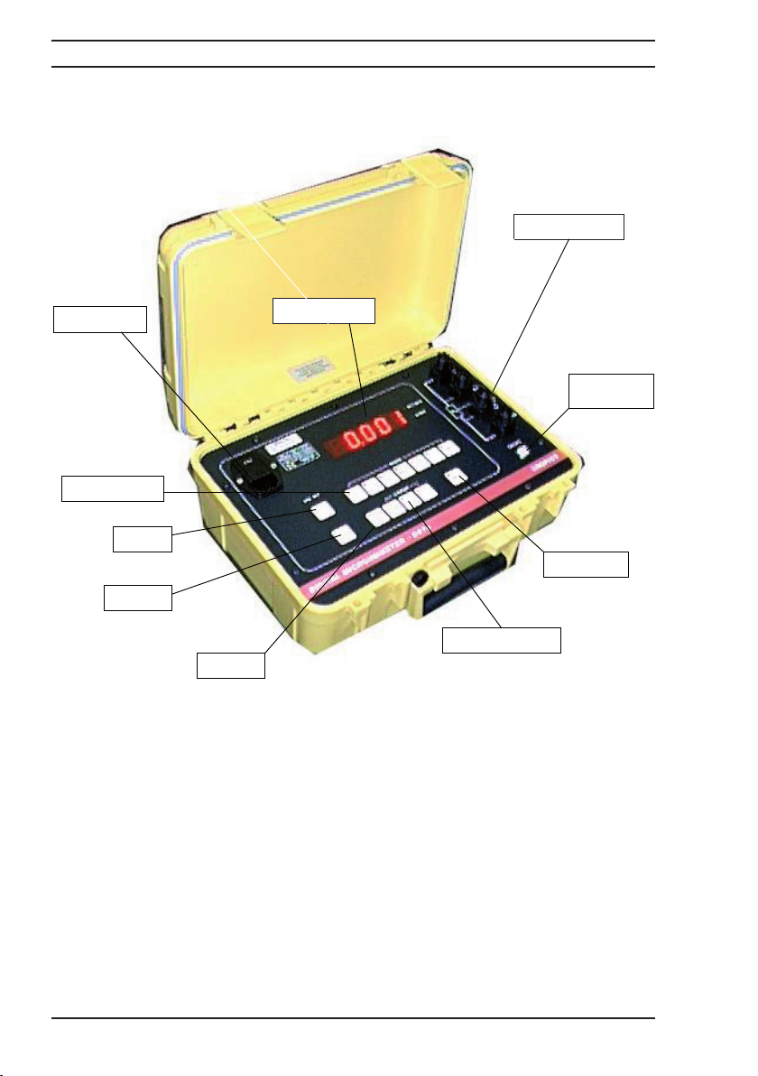
Digital Microhmmeter Type DO7e Operating Instructions
3