Crossbow Technology MPR2400 User manual

MPR/ MIB User’s Manual
Rev. A, August 2004
Document 7430-0021-06

© 2002-2004 Crossbow Technology, Inc. All rights reserved.
Information in this document is subject to change without notice.
Crossbow is a registered trademark. DMU is a trademark of Crossbow Technology, Inc. Other
product and trade names are trademarks or registered trademarks of their respective holders.

MPR/MIB User’s Manual
Wireless Sensor Networks
Doc. # 7430-0021-06 Rev. A Page 1
Table of Contents
1Introduction......................................................................................................................3
2MPR2400 (MICAz) ..........................................................................................................4
2.1 Product Summary..................................................................................................4
2.2 Block Diagram and Schematics for the MPR2400 / MICAz......................................4
2.3 FCC Certification for the MICAz............................................................................8
3MPR400/MPR410/MPR420 (MICA2)............................................................................9
3.1 Product Summary..................................................................................................9
3.2 Block Diagram and Schematics: MPR400/410/420 ..................................................9
4MPR500/MPR510/MPR520 (MICA2DOT).................................................................14
4.1 Product Summary................................................................................................ 14
4.2 On-board Thermistor ........................................................................................... 14
4.3 Block Diagram and Schematics for the MPR500/510/520 MICA2DOT................... 15
5MPR300/MPR310 (MICA)............................................................................................19
5.1 Schematic ........................................................................................................... 19
Power...............................................................................................................................20
6 20
6.1 Battery Power...................................................................................................... 20
6.2 External Power.................................................................................................... 21
6.3 MICAz Battery Voltage Monitor .......................................................................... 22
6.4 MICA2 Battery Voltage Monitor .......................................................................... 22
6.5 MICA2DOT Battery Voltage Monitor .................................................................. 23
7Radios ..............................................................................................................................24
7.1 MICA2 and MICA2DOT..................................................................................... 24
7.2 MICAz............................................................................................................... 26
8Antennas..........................................................................................................................29
8.1 Radio/Antenna Considerations ............................................................................. 29
8.2 Connectors for the MICA2 and MICAz and Whip Antennas................................... 29
9Flash Data Logger and Serial ID Chip.........................................................................31
10 Atmega128 Fuses............................................................................................................32
11 Sensor Boards & Expansion Connectors .....................................................................33
11.1 Sensor Board Compatibility ................................................................................. 33
11.2 MICAz and MICA2 Expansion Connector ............................................................ 33
11.3 MICA2DOT Expansion Connector ....................................................................... 35
12 MIB300 / MIB500 Interface Boards .............................................................................36

MPR/MIB User’s Manual
Wireless Sensor Networks
Doc. # 7430-0021-06 Rev. A Page 2
12.1 Programming the Mote ........................................................................................ 36
12.2 RS-232 Interface................................................................................................. 36
13 MIB510 Serial Interface Boards ...................................................................................37
13.1 Product Summary................................................................................................ 37
13.2 ISP ..................................................................................................................... 37
13.3 Mote Programming Using the MIB510 ................................................................. 37
13.4 Interfaces to MICAz, MICA2, and MICA2DOT.................................................... 38
14 MIB600CA......................................................................................................................42
14.1 Introduction ........................................................................................................ 42
14.2 Setup / Installation............................................................................................... 42
Host Software...................................................................................................... 44
14.3 44
14.4 MIB600 Use........................................................................................................ 44
JTAG.................................................................................................................. 45
14.5 45
15 Appendix A: 10/100 Base-T Cabling Standards ..........................................................47
16 Warranty and Support Information.............................................................................48
16.1 Customer Service ................................................................................................ 48
16.2 Contact Directory................................................................................................ 48
16.3 Return Procedure................................................................................................. 48
16.4 Warranty............................................................................................................. 49

MPR/MIB User’s Manual
Wireless Sensor Networks
Doc. # 7430-0021-06 Rev. A Page 3
1INTRODUCTION
This User’s Manualdescribes the hardware features of the Mote Processor Radio (MPR)
platforms and Mote Interface Boards (MIB) for network base stations and programming
interfaces. It is intended for understanding and leveraging Crossbow’s Smart Dust hardware
design in real-world sensor network, smart RFID, and ubiquitous computing applications. Table
Table 1-1below lists the models in this Manual. Table 1-2below summarizes the main features
of each Mote.
Table 1-1. This User’s Manual covers these MPR and MIB models.
MPR
2400
(MICAz)
400/410/420
(MICA2) 500/510/520
(MICA2DOT) 300/310
(MICA)
MIB 600 510 500 300
Table 1-2. Mote Product Summary.
Mote Hardware Platform MICAz MICA2 MICA2DOT MICA
Models (as ofAugust2004)MPR2400 MPR400/410/420 MPR500/510/520 MPR300/310
Chip ATMega128L ATMega103L
Type 7.37 MHz, 8 bit 4 MHz, 8 bit 4 MHz, 8 bit
MCU Program
Memory
(kB) 128
SRAM (kB) 4
Type 51 pin 18 pin 51 pin
10-Bit ADC 7, 0 V to 3 V input 6, 0 V to 3 V
input 7, 0 V to 3 V
input
UART 212
Sensor Board Interface
Other
interfaces DIO, I2C DIO DIO, I2C
Chip CC2420 CC1000 TR1000
Radio
Frequency
(MHz) 2400 315/433/915 433/915
Max. Data
Rate
(kbits/sec) 250 38.4 40
RF Transceiver (Radio)
Antenna
Connector MMCX PCB solder hole
Chip AT45DB014B
Connection
Type SPIFlash Data Logger
Memory Size (kB) 512
Type AA, 2× Coin (CR2354) AA, 2×
Typical
capacity
(mA-hr) 2000 560 2000
Default power source
3.3V
booster N/A ü
This Manual is not a software guide to programming the motes in TinyOS/nesC, nor is it a guide
to pre-built software packages that run on top of the Motes. The following two resources are
available regarding software:

MPR/MIB User’s Manual
Wireless Sensor Networks
Doc. # 7430-0021-06 Rev. A Page 4
qTinyOS Getting Started Guide by Crossbow Technology, Inc. available on the TinyOS
Support Tools CDROM or the Crossbow web site at www.xbow.comunder Support>User’s
Manuals.
qThe TinyOS web site at http://webs.cs.berkeley.edu/tos

MPR/MIB User’s Manual
Wireless Sensor Networks
Doc. # 7430-0021-06 Rev. A Page 5
2MPR2400 (MICAZ)
2.1 Product Summary
The MICAz is the latest generation of Motes from Crossbow Technology. The MPR2400 (2400
MHzto 2483.5 MHz band) uses the Chipcon CC2420, IEEE 802.15.4 compliant, ZigBee ready
radio frequency transceiver integrated with an Atmega128L micro-controller. The same MICA2,
51 pin I/O connector, and serial flash memory is used;all MICA2 application software and
sensor boards are compatible with the MPR2400.
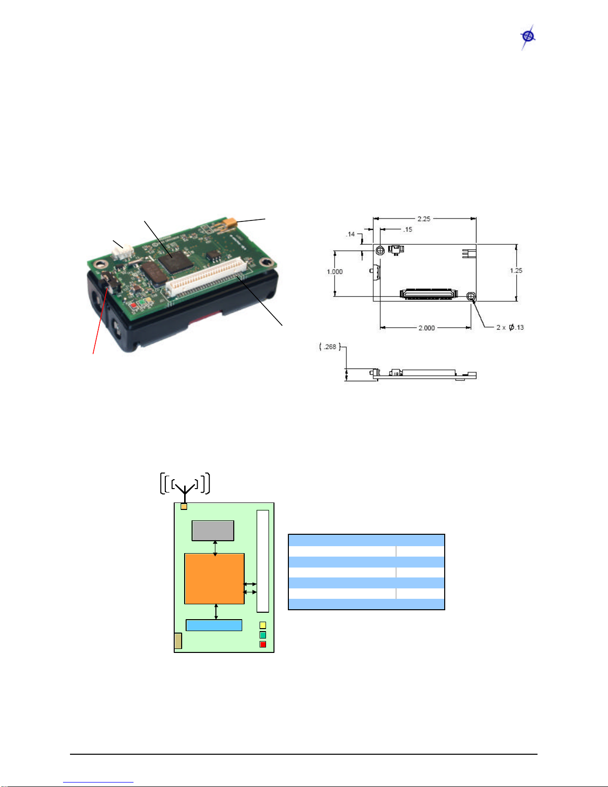
Figure 2-1. Photo of the MPR2400—MICAz with standard antenna. For the dimensions of the
board and locations of the mounting holes, see Figure 2-2.
2.2 Block Diagram and Schematics for the MPR2400 / MICAz
Feature Chapter
Batteries 6
Radio 7
Antenna 8
Data Flash Logger 9
Atmega128 10
Expansion Connector 11
Figure 2-1. Block diagram of the MICA2 and listing of Chaptersthat discuss the components in
greater detail.
Logger
Flash
ATMega128L
µcontroller
Analog I/O
Digital I/O
CC2420 DSSS
Radio
51-Pin Expansion Connector
Antenna
MMCX connector
LEDs
Logger
Flash
ATMega128L
µcontroller
Analog I/O
Digital I/O
CC2420 DSSS
Radio
51-Pin Expansion Connector
Antenna
MMCX connector
LEDs
MPR/MIB User’s Manual
Wireless Sensor Networks
Doc. # 7430-0021-06 Rev. A Page 6
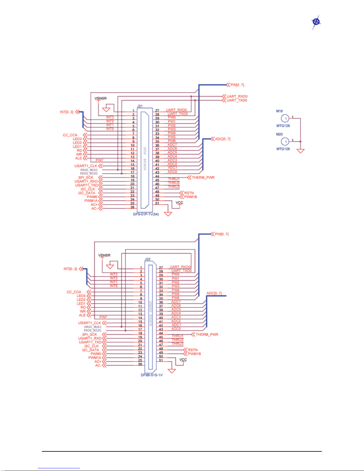
2.2.1 51-pin Expansion Connector
MPR/MIB User’s Manual
Wireless Sensor Networks
Doc. # 7430-0021-06 Rev. A Page 7
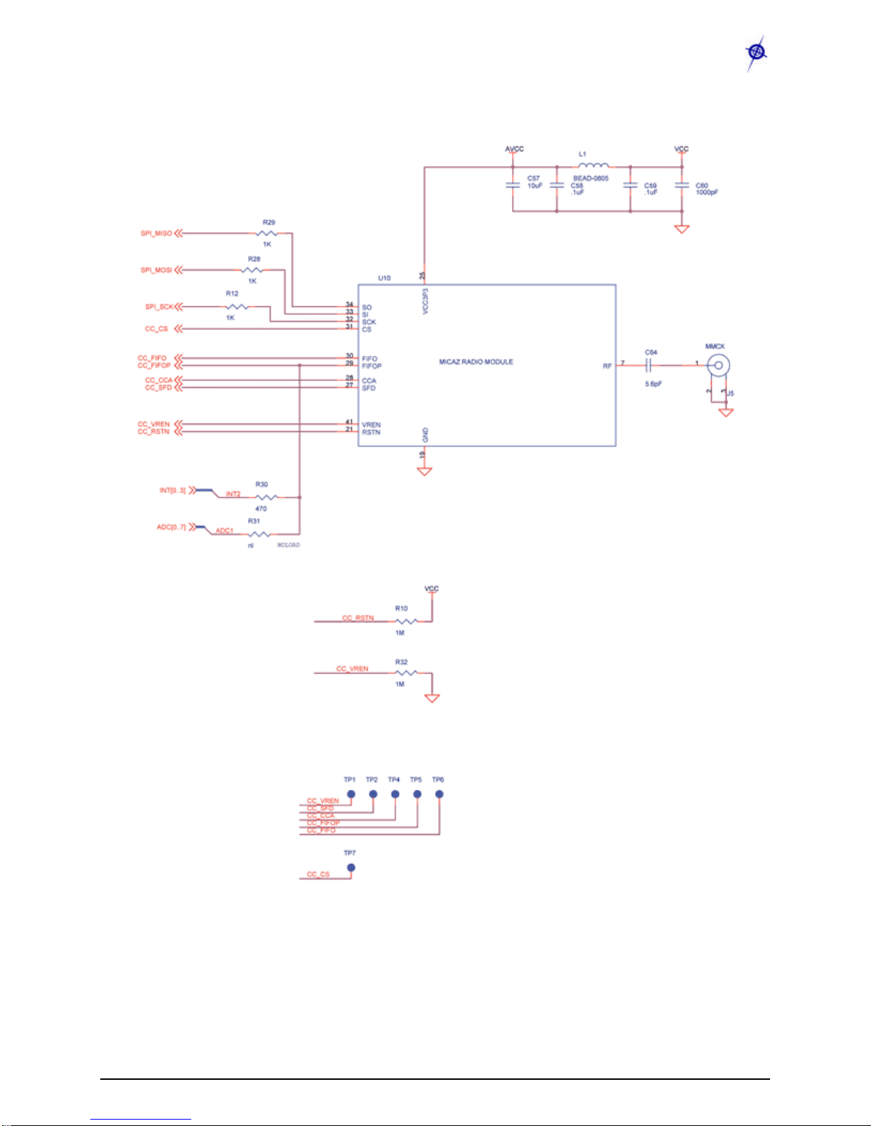
2.2.2 CC2420 Radio
MPR/MIB User’s Manual
Wireless Sensor Networks
Doc. # 7430-0021-06 Rev. A Page 8
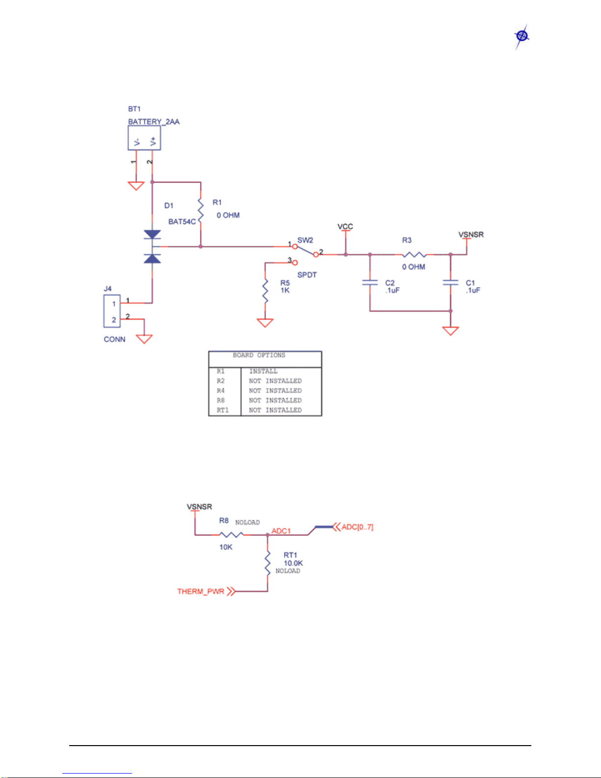
2.2.3 Battery, ADC1

MPR/MIB User’s Manual
Wireless Sensor Networks
Doc. # 7430-0021-06 Rev. A Page 9
2.3 FCC Certification for the MICAz
The MICAz Mote is classified by the FCC as both a Class A and a Class B digital device. As
such this section describes how to operate the equipment so that it does not cause unintended RF
interference.
2.3.1 Class A & B Digital Device Compliance
This equipment has been tested by the FCC and found to comply with the limits for a Class A
digital device, pursuant to Part 15 of the FCC Rules. These limits are designed to provide
reasonable protection against harmful interference when the equipment is operated in a
commercial environment. This equipment generates, uses, a nd can radiate radio frequency
energy and, if not installed and used in accordance with the instruction manual, may
cause harmful interference to radio communications. There is no guarantee that interference will
not occur in a commercial environment. Howe ver, operation of this equipment in a residential
area is likely to cause harmful interference, which can be determined by turning the equipment
off and on. If this is the case the user is encouraged to try and correct the interference by
one or more of the following measures:
qReorient or locate the receiving antenna.
qIncrease the separation between the equipment and receiver.
qConnect the equipment into an outlet on a circuit different from that to which the receiver is
connected.
qConsult the dealer or an experienced radio/TV technician for help.
If these measures do not correct for RF interference, the user will be required to correct the
interference at his own expense.
IWARNING: Any modifications to the unit, unless expressly approved by Crossbow
Technology, Inc. could void the user’s authority to operate the MICAz Mote (also referred to as
“equipment” in this Section).
MPR/MIB User’s Manual
Wireless Sensor Networks
Doc. # 7430-0021-06 Rev. A Page 10
3MPR400/MPR410/MPR420 (MICA2)
3.1 Product Summary
The MICA2 Motes come in three models according to their RF frequency band: the MPR400
(915 MHz), MPR410 (433 MHz), and MPR420 (315 MHz). The Motes use the Chipcon
CC1000, FSK modulated radio. All models utilize a powerful Atmega128L micro-controller and
a frequency tunable radio with extended range. The MPR4x0 and MPR5x0 radios are compatible
and can communicate with each other. (The x= 0, 1, or 2 depending on the model / frequency
band.)
Figure 3-1. Left: Photo of a MICA2 (MPR4x0) without an antenna.Right: Top and plan views
showing the dimensions and hole locations of the MICA2 PCB without the battery pack.
3.2 Block Diagram and Schematics: MPR400/410/420
Feature Chapter
Battery / Ext. Power 6
Radio 7
Antenna 8
Data Flash Logger 9
Atmega128 10
Expansion Connector 11
Figure 3-2. Block diagram of the MICA2 and listing of Chapters that discuss the components in
greater detail.
MMCX connector
(female)
51-pin Hirose connector
(male)
On/Off Switch
External power
connector
Atmel®ATMega128
Logger
Flash
ATMega128L
µcontroller
Analog I/O
Digital I/O
CC1000 FSK
51-Pin Expansion Connector
Antenna
MMCX connector
LEDs
Power
Connector
Logger
Flash
ATMega128L
µcontroller
Analog I/O
Digital I/O
CC1000 FSK
51-Pin Expansion Connector
Antenna
MMCX connector
LEDs
Power
Connector

MPR/MIB User’s Manual
Wireless Sensor Networks
Doc. # 7430-0021-06 Rev. A Page 11
3.2.1 Battery, Power, and ADC1
VSNSR
INSTALL
NOT INSTALLED
NOT INSTALLED
NOT INSTALLED
NOT INSTALLED
J4
CONN
1
2
1
2
SW2
SPDT
12
3
R8
10K
U2
LM4041-1.2
1
23
R1
0 OHM
TP3
R1
R2
R4
R8
RT1
D1
BAT54C
BAT_MON
BOARD OPTIONS
R2
0 OHM
R4
0 OHM
ADC7
R5
1K
VCC
C2
.1uF C1
.1uF
BT1
BATTERY_2AA
1
2V-
V+
R6
10K
ADC1
R3
0 OHM
VSNSR
THERM_PWR
ADC[0..7]
RT1
10.0K
R7
18.2K
3.2.2 CC1000
AVCC
R12
10K
L5
R11
1M
CHP_OUT
6310-0306-01 A
MICA2 MPR410CB-433MHZ
B
2 6Friday, March 21, 2003
Title
Size Document Number Rev
Date: Sheet of
AVCC
R10
1M
L2
C18
4.7pF
RADIO DATA
L4
C14
Y4
14.7456MHZ
21 21
C19
13pF
C13
R9
1M
C6
.001uF
PDATA
L1
BEAD-0805
C11
.001uF
L3
J5
MMCX
1
2
3
VCC
R13
27.4K
C16
.001uF
AVCC
J3
HDR 2 X 1 X .1
1
21
2
U3
CC1000
21
1
5
9
15
3
4
10
11
12
13 18
17
23
24
25
26
27 28
VCC
AVCC
AVCC
AVCC
AVCC
RF_IN
RF_OUT
L1
L2
CHP_OUT
R_BIAS XOSC1
XOSC2
DIO
DCLK
PCLK
PDATA
PALE RSSI
C12
C7
.001uF
C17
RADIO CONTROL
VCC
C15
AVCC
PALE
PDATA
C10
0.033uF
C5
0.033uF
DCLK
PCLK
SPI_SCK
SPI_MOSI
SPI_MISO
CHP_OUT
ADC0 (RSSI)
C9
220PF
PALE
SPI_MISO
PCLK
PDATA
PALE
R14
82.5K
ADC0
C20
13pF
SPI_SCK
VCC
VCCC8
220PF
DCLK
MPR/MIB User’s Manual
Wireless Sensor Networks
Doc. # 7430-0021-06 Rev. A Page 12
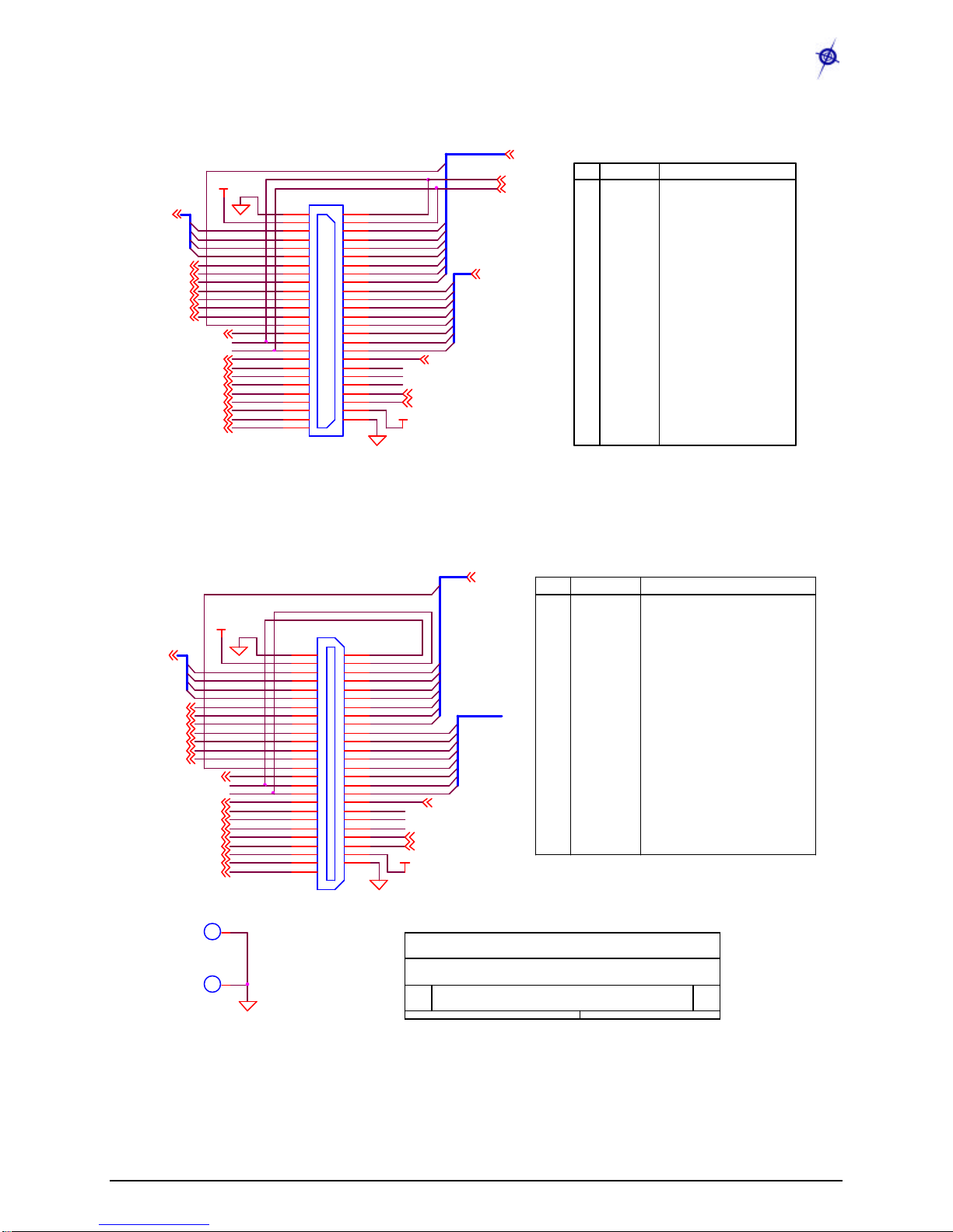
3.2.3 51-pin Expansion Connector: Location J21
ADC4
AC+
SPI_SCK
UART_RXD0
USART1_RXD
DESCRIPTION
ADC3
PW2
ALE
PWM1A
ADC2
BAT_MON
GND
VSNSR
INT3
INT2
INT1
INT0
BAT_MON
LED3
LED2
LED1
RD
WR
ALE
PW7
USART1_CLK
PROG_MOSI
PROG_MISO
SPI_SCK
USART1_RXD
USART1_TXD
I2C_CLK
I2C_DATA
PWM0
PWM1A
AC+
AC-
NAME
ADC7
PW5
INT1
ADC1
PIN
THRU3
LED3
LED1
ADC[0..7]
I2C_CLK
PWM1B
AC-
PWM0 RSTN
UART_TXD0
RD
INT2
ADC5
INT3
THERM_PWR
PW4
UART_RXD0
THRU1
USART1_CLK
PROG_MISO
ADC6
PW1
INT[0..3]
1
2
3
4
5
6
7
8
9
10
11
12
13
14
15
16
17
18
19
20
21
22
23
24
25
26
VCC
HIROSE PLUG
J21
DF9-51P-1V(54)
1
2
3
4
5
6
7
8
9
10
11
12
13
14
15
16
17
18
19
20
21
22
23
24
25
26
27
28
29
30
31
32
33
34
35
36
37
38
39
40
41
42
43
44
45
46
47
48
49
50
51
WR
PROG_MOSI
THRU2
LED2
PW0
PW6
ADC0
VSNSR
I2C_DATA
PW7
INT0 PW3
UART_TXD0
USART1_TXD
GROUND
SENSOR SUPPLY
GPIO
GPIO
GPIO
GPIO
BATTERY VOLTAGE MONITOR ENABLE
LED3
LED2
LED1
GPIO
GPIO
GPIO
POWER CONTROL 7
USART1 CLOCK
SERIAL PROGRAM MOSI
SERIAL PROGRAM MISO
SPI SERIAL CLOCK
USART1 RX DATA
USART1 TX DATA
I2C BUS CLOCK
I2C BUS DATA
GPIO/PWM0
GPIO/PWM1A
GPIO/AC+
GPIO/AC-
PW[0..7]
3.2.4 51-pin Expansion Pads: Location J22
THRU1
PW4
AC+
ALE
THRU2
PROG_MISO
UART_TXD0
PWM0
I2C_DATA
ADC[0..7]
PW1
PW[0..7]
I2C_CLK
ADC6
THRU3
PW2
USART1_RXD
SPI_SCK
BAT_MON
6310-0306-01 A
MICA2 MPR410CB-433MHZ
CROSSBOW TECHNOLOGY. INC.
B
4 6Friday, March 21, 2003
Title
Size Document Number Rev
Date: Sheet of
PW6
INT0
UART_RXD0
UART_TXD0
PW0
PW1
PW2
PW3
PW4
PW5
PW6
ADC7
ADC6
ADC5
ADC4
ADC3
ADC2
ADC1
ADC0
THERM_PWR
THRU1
THRU2
THRU3
RSTN
PWM1B
VCC
GND
ADC5
PWM1B
AC-
ADC3
PWM1A
INT1
LED1
ADC0
USART1_CLK ADC1
THERM_PWR
NAME DESCRIPTION
ADC7
USART1_TXD
M20
MTG128
1
1
VSNSR
INT3
PROG_MOSI
ADC4
HIROSE SOCKET
J22
DF9B-51S-1V
1
2
3
4
5
6
7
8
9
10
11
12
13
14
15
16
17
18
19
20
21
22
23
24
25
26
27
28
29
30
31
32
33
34
35
36
37
38
39
40
41
42
43
44
45
46
47
48
49
50
51
M18
MTG128
1
1
INT[0..3]
WR
PW3
RSTN
PW7
UART_0 RECEIVE
UART_0 TRANSMIT
POWER CONTROL 0
POWER CONTROL 1
POWER CONTROL 2
POWER CONTROL 3
POWER CONTROL 4
POWER CONTROL 5
POWER CONTROL 6
ADC INPUT 7 - BATTERY MONITOR/JTAG TDI
ADC INPUT 6 / JTAG TDO
ADC INPUT 5 / JTAG TMS
ADC INPUT 4 / JTAG TCK
ADC INPUT 3
ADC INPUT 2
ADC INPUT 1
ADC INPUT 0 / RSSI MONITOR
TEMP SENSOR ENABLE
THRU CONNECT 1
THRU CONNECT 2
THRU CONNECT3
RESET (NEG)
GPIO/PWM1B
DIGITAL SUPPLY
GROUND
LED2
VCC
UART_RXD0
PIN
PW5
PW0
ADC2
INT2
LED3
RD
27
28
29
30
31
32
33
34
35
36
37
38
39
40
41
42
43
44
45
46
47
48
49
50
51
MPR/MIB User’s Manual
Wireless Sensor Networks
Doc. # 7430-0021-06 Rev. A Page 13
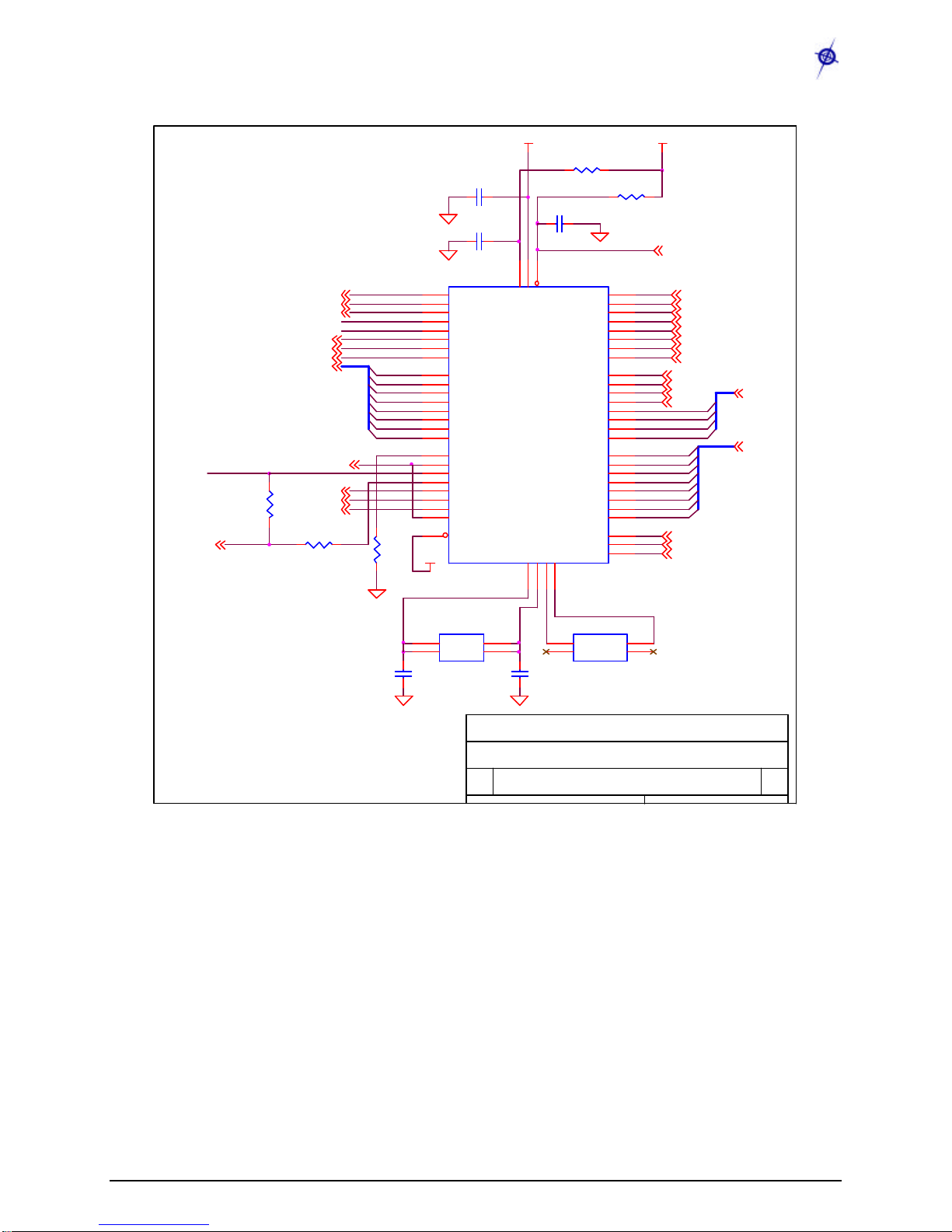
3.2.5 ATMega128L
VCC
BAT_MON
C23
.1uF
SPI_MISO
INT0
PW6
RD
INT3
ADC7
PWM1A
C36
13pF
R20
10K
VSNSR
ADC5
LED3
PW0
Y3
32.768KHZ
4
3 2
1
X2
GND GND
X1
UART_TXD0
I2C_CLK
LED1
AC+
PW5
R16
10K
PW3
C22
.1uF
U7
ATMEGA128L
51
50
49
48
47
46
45
44
10
11
12
13
14
15
16
17
35
36
37
38
39
40
41
42
25
26
27
28
29
30
31
32
2
3
4
5
6
7
8
9
61
60
59
58
57
56
55
54
64
62
1
20
24
23
33
34
43
18
19
PA0/AD0
PA1/AD1
PA2/AD2
PA3/AD3
PA4/AD4
PA5/AD5
PA6/AD6
PA7/AD7
PB0/SS
PB1/SCK
PB2/MOSI
PB3/MISO
PB4/OC0
PB5/OC1A
PB6/OC1B
PB7/OC1C
PC0/A8
PC1/A9
PC2/A10
PC3/A11
PC4/A12
PC5/A13
PC6/A14
PC7/A15
PD0/I2C_CLK
PD1/I2C_DATA
PD2/RXD1
PD3/TXD1
PD4/IC1
PD5/XCK1
PD6/T1
PD7/T2
PE0/RXD0
PE1/TXD0
PE2/XCK0
PE3/OC3A
PE4/OC3B
PE5/OC3C
PE6/T3
PE7/IC3
PF0/ADC0
PF1/ADC1
PF2/ADC2
PF3/ADC3
PF4/TCK
PF5/TMS
PF6/TDO
PF7/TDI
AVCC
AREF
PEN
RST
XTAL1
XTAL2
PG0/WR
PG1/RD
PG2/ALE
PG3/TOSC2
PG4/TOSC1
USART1_CLK
C21
.1uF
FLASH_CS
WR
SPI_SCK ADC2
ADC3
R21
10K
PW1
CHP_OUT
THERM_PWR
PWM1B
RSTN
ADC4
VCC
PALE
AC-
INT2
LED2
ADC1
PWM0
USART1_RXD
PW4
R18
0 OHM
SERIAL_ID
R15
470
UART_RXD0
INT[0..3]
C35
13pF
I2C_DATA
PW[0..7]
6310-0306-01 A
MICA2 MPR410CB-433MHZ
CROSSBOW TECHNOLOGY. INC.
B
5 6Friday, March 21, 2003
Title
Size Document Number Rev
Date: Sheet of
ADC0
ADC6
ALE
PDATA
PCLK
Y2
7.3728MHZ
2
34
1X2
X2X1
X1
PW7
ADC[0..7]
SPI_MOSI
USART1_TXD
PW2
INT1
MPR/MIB User’s Manual
Wireless Sensor Networks
Doc. # 7430-0021-06 Rev. A Page 14
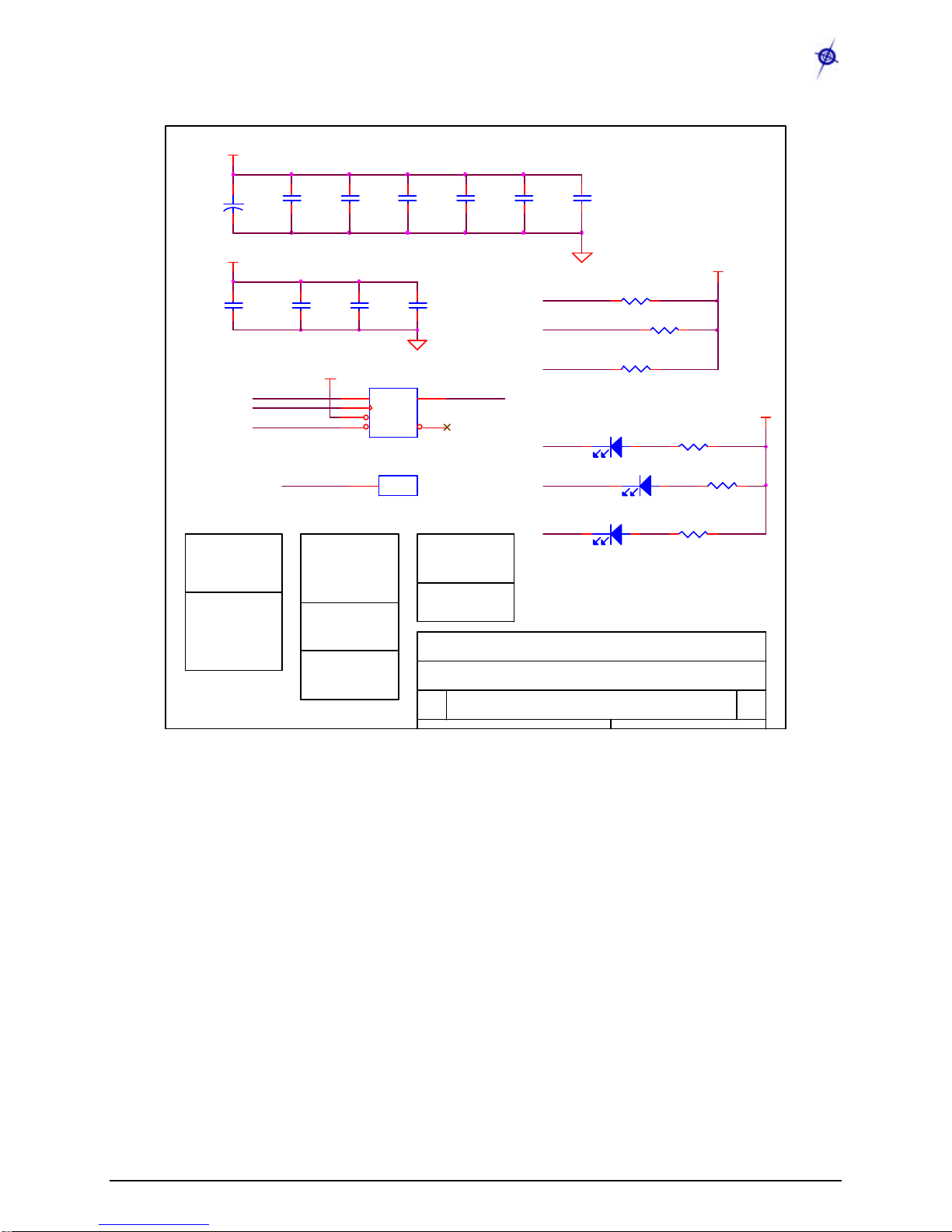
3.2.6 Flash Memory, Serial ID, LEDs, USART
SERIAL_ID
VCC
PCLK
PDATA
PALE
D2
RED
12
6310-0306-01 A
MICA2 MPR410CB-433MHZ
CROSSBOW TECHNOLOGY. INC.
B
6 6Friday, March 21, 2003
Title
Size Document Number Rev
Date: Sheet of
C27
.01uF
FLASH INTERFACE
USART1_CLK
C28
.01uF
RADIO CONTROL
C32
1000pF
R23
4.7K
VCC
C30
.01uF
USART1_TXD U5
AT45DB041
1
2
3
4 5
8
SI
SCK
RST
CS WP
SO
UART INTERFACE
UART_RXD0
UART_TXD0
CONTROL INTERFACE
R19
1M
LED2
U6
DS2401P
2DQ
D4
YELLOW
12
USART1_RXD
+
C24
10uF
10V
R27
470
I2C_CLK
I2C_DATA
SPI_SCK
SPI_MOSI
SPI_MISO
CHP_OUT
ADC0
(RSSI)
RADIO DATA
LED1
ADC7
C29
.01uF
C25
.01uF
R25
470
R22
1M
VCC
C33
1000pF
LED3
FLASH_CS
FLASH_CS
VCC
D3
GREEN
12
FLASH_SI
FLASH_SO
FLASH_CLK
SERIAL_ID
SENSOR INTERFACE
R26
470
PW[0..7]
ADC[1..6]
USART1_RXD
VCC
VCC MONITOR
UART_TXD0
C31
1000pF C34
1000pF
C26
.01uF
MPR/MIB User’s Manual
Wireless Sensor Networks
Doc. # 7430-0021-06 Rev. A Page 15
4MPR500/MPR510/MPR520 (MICA2DOT)
4.1 Product Summary
The MICA2DOT is a Mote designed for applicationswhere physical size is important. Like the
MICA2, these are available in three models according to the frequency of the RF transceiver: the
MPR500 (915MHz), MPR510 (433 MHz), and MPR520 (315 MHz). The Motes use the
Chipcon CC1000 FSK-modulated radio. All models utilize a powerful ATMega128L micro-
controller and a frequency tunable radio with extended range. The MPR4x0 and MPR5x0 radios
are compatible and can communicate with each other as long as the “x” is the same number.
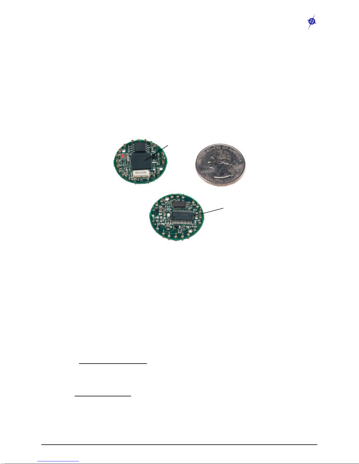
Figure 4-1. Photos of the MICA2DOT shown next to a US quarter: a) Top-side and b) Bottom-
side. Typically the MICA2DOT has a 3 V coin-cell battery holder attached to the bottom-side,
but it has been removed to show the details.
4.2 On-board Thermistor
The MICA2DOT Mote has an on-board thermistor (Panasonic ERT-J1VR103J) which is a
surface mount component. It is on the ATMega128 side of the board at the location labeled
“RT1.”Its output is at ADC1 and is enabled by setting PW6 (PC6/A14) to “LO”and PW7
(PC7/A15) to “HI.”
The Mote’s ADC output can be converted to degrees kelvin in the 273.15 K to 323.15 K (0°C to
50 °C) range using the Steinhart-Hart equation, which is a widely used third-order
approximation.
3
)(lnln 1
)(
thrthr RcRba
KT++
=
where:
( )
ADCFSADC ADCR
Rthr −
×
=_
1
and a, band care called the Steinhart-Hart parameters with the following values:
a= 0.00130705
(a) Top-side
(b) Bottom-side
Atmel®ATMega128
Chipcon®CC1000

MPR/MIB User’s Manual
Wireless Sensor Networks
Doc. # 7430-0021-06 Rev. A Page 16
b= 0.000214381
c= 0.000000093
R1= 10 k?
ADC_FS = 1023
ADC = output value from the Mote’s ADC measurement.
4.3 Block Diagram and Schematics for the MPR500/510/520 MICA2DOT
Feature Chapter
Battery / Ext. Power 6
Radio 7
Antenna 8
Data Flash Logger 9
Atmega128 10
Expansion Connector 11
Figure 4-1.Block diagram of the MICA2DOT and listing of Chapters that discuss the
components in greater detail.
ATMega128L
µcontroller
Analog I/O
Digital I/O
Freq.
Tunable
Radio
Logger Flash
AntennaAntenna
25 mm
19 peripheral pins

MPR/MIB User’s Manual
Wireless Sensor Networks
Doc. # 7430-0021-06 Rev. A Page 17
4.3.1 MICA2DOT CC1000 Radio Side
R13
10K
R17
27.4K
L3
R11
1M
VCCA
C12
AVCC
L4
TP18
PDATA
VCCA
C6
220PF
PDATA
C4
.001uF
PALE
C9
.001uF
AVCC
6310-0300-01 A
MICA DOT2 RADIO SIDE
B
1 3Wednesday, March 26, 2003
Title
Size Document Number Rev
Date: Sheet of
DCLK
L2
BEAD-0805
C3
0.033uF R12
1M
AVCC
C10
DCLK
C20
13pF
AVCC
U3
CC1000
21
1
5
9
15
3
4
10
11
12
13 18
17
23
24
25
26
27 28
VCC
AVCC
AVCC
AVCC
AVCC
RF_IN
RF_OUT
L1
L2
CHP_OUT
R_BIAS XOSC1
XOSC2
DIO
DCLK
PCLK
PDATA
PALE RSSI POT_PWR
SPI_MISO
SPI_SCK
L9
VCCA
C18C16
.001uFC17
4.7pF
R18
82.5K
PALE
TP17
Y1
14.7456MHZ
21 X2X1
C19
C13
PCLK
VCCA
INT3
ADC0
L8
R10
1M
C21
13pF
R35
10K

MPR/MIB User’s Manual
Wireless Sensor Networks
Doc. # 7430-0021-06 Rev. A Page 18
4.3.2 MIC2DOT ATMega128L, ADC Interfaces, Battery
PW5
Y5
32.768KHZ
32
1NCX2
X1
SPI_MOSI
INT0
SPI_SCK
PDATA
VCCA
R22
10K
PWM1B
PW[0..7]
R21
470
ADC1
POT_PWR
LED2
UART_RXD0
INT1
ALE
ADC6
ADC5
AC+
LED3
VCCA
DC_BOOST_SHDN
PW7
PWM0
SERIAL_ID
SPI_MISO
ADC3
PWM1A
INT2
Y4
4.000MHZ
6
52
1
3 4
X1
GNDGND
X1
X2 X2
PW2
ADC4
RSTN
U6
ATMEGA128LMLF
21
52
22
53
63
51
50
49
48
47
46
45
44
10
11
12
13
14
15
16
17
35
36
37
38
39
40
41
42
25
26
27
28
29
30
31
32
2
3
4
5
6
7
8
9
61
60
59
58
57
56
55
54
64
62
1
20
24
23
33
34
43
18
19
VCC
VCC
GND
GND
GND
PA0/AD0
PA1/AD1
PA2/AD2
PA3/AD3
PA4/AD4
PA5/AD5
PA6/AD6
PA7/AD7
PB0/SS
PB1/SCK
PB2/MOSI
PB3/MISO
PB4/OC0
PB5/OC1A
PB6/OC1B
PB7/OC1C
PC0/A8
PC1/A9
PC2/A10
PC3/A11
PC4/A12
PC5/A13
PC6/A14
PC7/A15
PD0/INT0
PD1/INT1
PD2/RXD1
PD3/TXD1
PD4/IC1
PD5/XCK1
PD6/T1
PD7/T2
PE0/RXD0
PE1/TXD0
PE2/XCK0
PE3/OC3A
PE4/OC3B
PE5/OC3C
PE6/T3
PE7/IC3
PF0/ADC0
PF1/ADC1
PF2/ADC2
PF3/ADC3
PF4/TCK
PF5/TMS
PF6/TDO
PF7/TDI
AVCC
AREF
PEN
RST
XTAL1
XTAL2
PG0/WR
PG1/RD
PG2/ALE
PG3/TOSC2
PG4/TOSC1
ADC7
C23
.1uF
R28
10K
PALE
ADC2
GPS_ENA
C22
.1uF
PW3 AC-
PCLK
LED1
PW6
RD
VCCA
PW0
ADC[0..7]
SPI_MOSI
I2C1_DATA
FLASH_SI
FLASH_SO
R27
10K
PW1
ADC0
FLASH_CLK
UART_TXD0
PW4
I2C1_CLK
WR
INT3
INT0
TP8
TP19
ADC[0..7]
TP10TP7
PW1
SPI_SCK
RSTN
ADC3
TP6 TP11
TP13
PW0
TP20
ADC5
TP4
VCCA
ADC2
PWM1B
TP15
BT1
BATTERY
1 2
TP2
VCCA
TP9
TP1
ADC7
ADC6
TP21
GPS_ENA
PW[0..7]
ADC4
TP5TP3 TP12
TP14
INT1
UART_TXD0
UART_RXD0
This manual suits for next models
12
Table of contents
Popular Transmitter manuals by other brands


ADEMCO
ADEMCO 5819WHS - Ademco Wireless Shock Processor installation instructions

Endress+Hauser
Endress+Hauser Prosonic S FMU90 operating instructions

NEO
NEO YR2116 quick start guide

Ikan
Ikan Blitz 400 user guide

Intelix
Intelix AVO-V1A2-WP110-EU installation manual

Sentera Controls
Sentera Controls DSMFM-2R Mounting and operating instructions


