About
■Specifications:
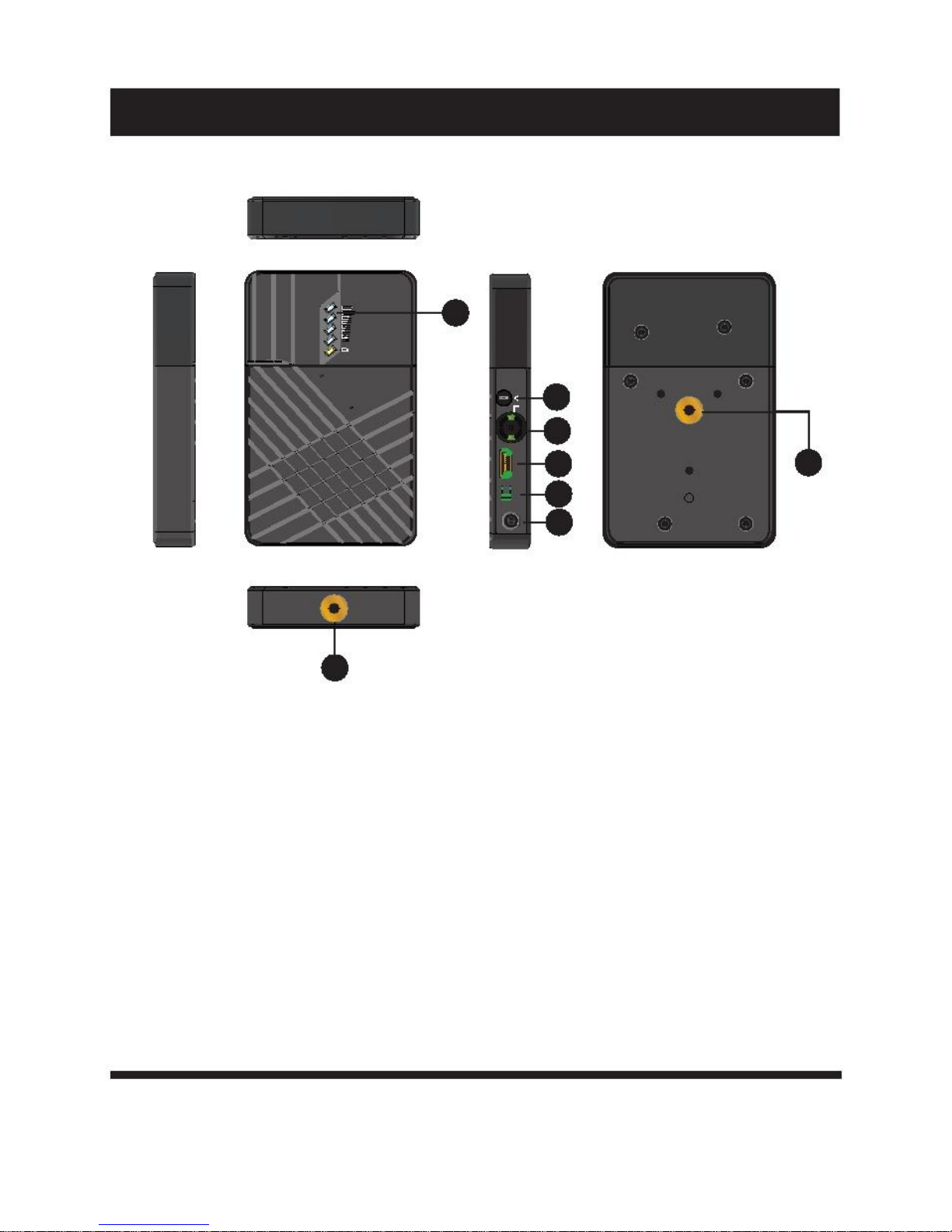
Transmitter Receiver
SDI Input(BNC Female )HDMI ; SDI Output(BNCFemale )HDMI ;
Interface Input (Type Afemale) ; 2 Antenna port(RP- Output (Type A female); DC input
SMA male);DCinput
Supply voltage range
Power consumption
Size
Mass Weight
Input Video Format
Output Video Format
Input Audio Format
Output Audio
Signal Indicator
Frequency Band
Modulation Mode
Transmission Power
Receiver Sensitivity
Occupied Bandwidth
Temperature Range
Compliance
7-36VDC
<6.5W
(L x W x H): 115x 67 x 23mm
doesn'tincludeantennas
270g
HDMI:525i, 625i, 720p 50/59.94/60,
1080i 50/59.94/60, 1080p23.98/24/25/2
9.9/30/50/59.94/60;HDMI Type A
SDI:3G, HD, and SD-SDI (auto-selected),
SMPTE-
259/274/292/296/372/424/425;1x BNC
/
SDI embedded 2 channel 24 bit/48KHz
/
POWER-Green; VIDEO-Yellow
5.1-5.9GHz,configurable with China,
North American, Europe,etc
OFDM16QAM
Maximum 18dBm
/
40MHz
0~40°C(operating condition);
-20~60°C(Storage)
FCC;CE.
7-36VDC
<7.5W
(L x W x H): 152x 95 x 23mm
355g
/
HDMI:525i, 625i, 720p 50/59.94/60,
1080i 50/59.94/60,1080p23.98/24/25/2
9.9/30/50/59.94/60;HDMI Type A
SDI:3G, HD, and SD-SDI (auto-selected),
SMPTE-259/274/292/296/372/424/425;
1xBNC
/
SDI embedded 2 channel 24 bit/48KHz
POWER-Green; Wireless RSSI-Blue (4
LEDs); POWER/VIDEO-Yellow
5.1-5.9GHz,configurable with China,
North American, Europe,etc
OFDM16QAM
/
-75dBm
40MHz
0 ~ 40°C (operating condition);
-20~60°C(Storage)
FCC;CE.
7