crosscontrol CCpilot X1400 User manual

CCpilot X1400
Product revision: 1.0
Technical manual
2022-12-20
CCpilot X1400
Technical manual

CCpilot X1400
Product revision: 1.0
Technical manual
2022-12-20
Contents
1. Introduction............................................................................................................................... 3
1.1. Product Models.................................................................................................................... 3
1.2. Conventions and Definitions .............................................................................................. 3
1.3. Identification ........................................................................................................................ 3
1.4. Maintenance and Care ..................................................................................................... 3
1.5. Cleaning ............................................................................................................................... 4
1.6. Environment and Environmental Tolerance ..................................................................... 4
1.7. Supporting Documentation................................................................................................ 4
2. Device Overview...................................................................................................................... 5
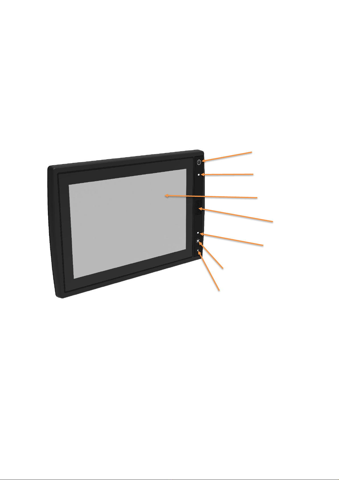
2.1. Front Side .............................................................................................................................. 5
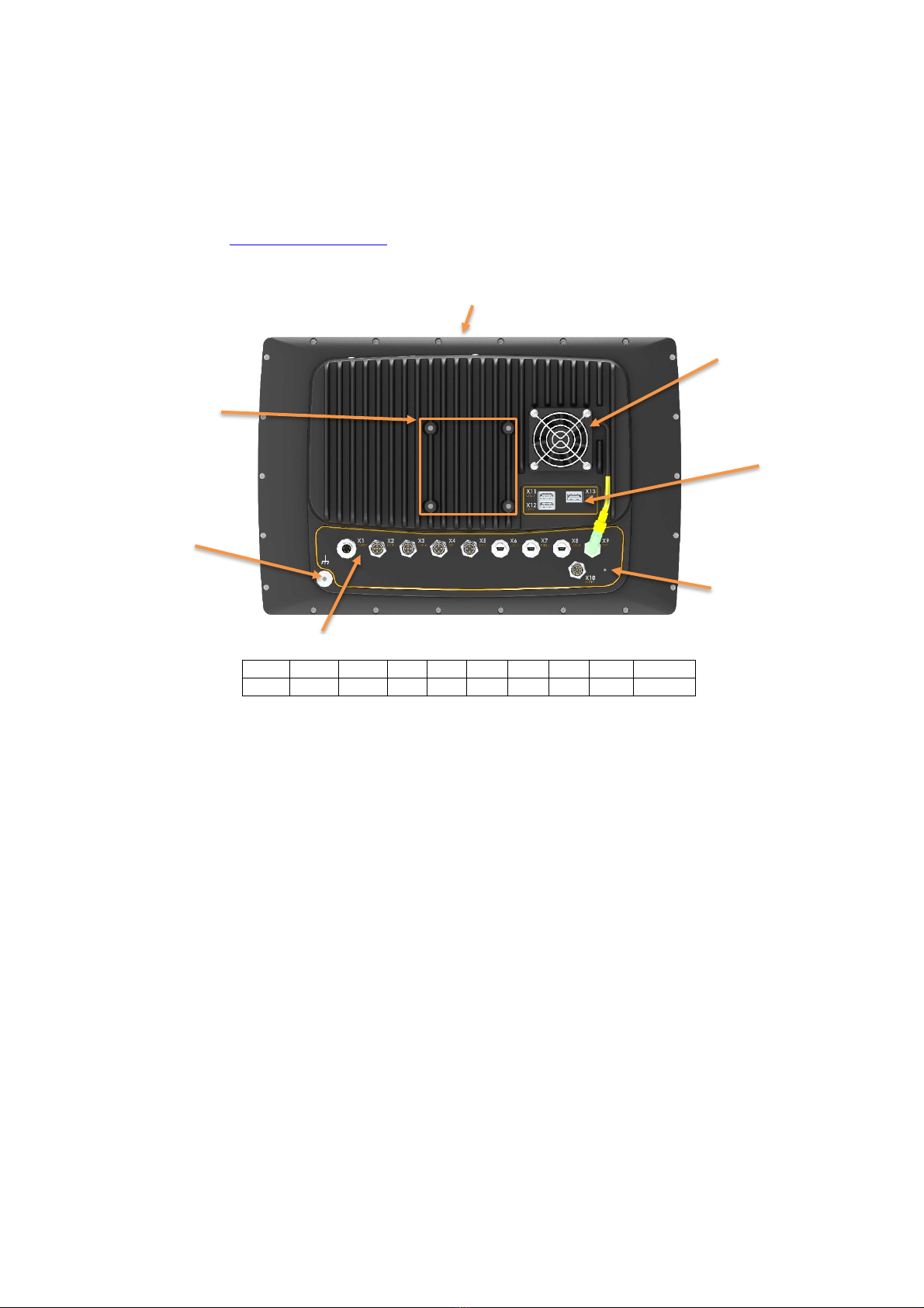
2.2. Rear Side............................................................................................................................... 6
3. Installation................................................................................................................................. 7
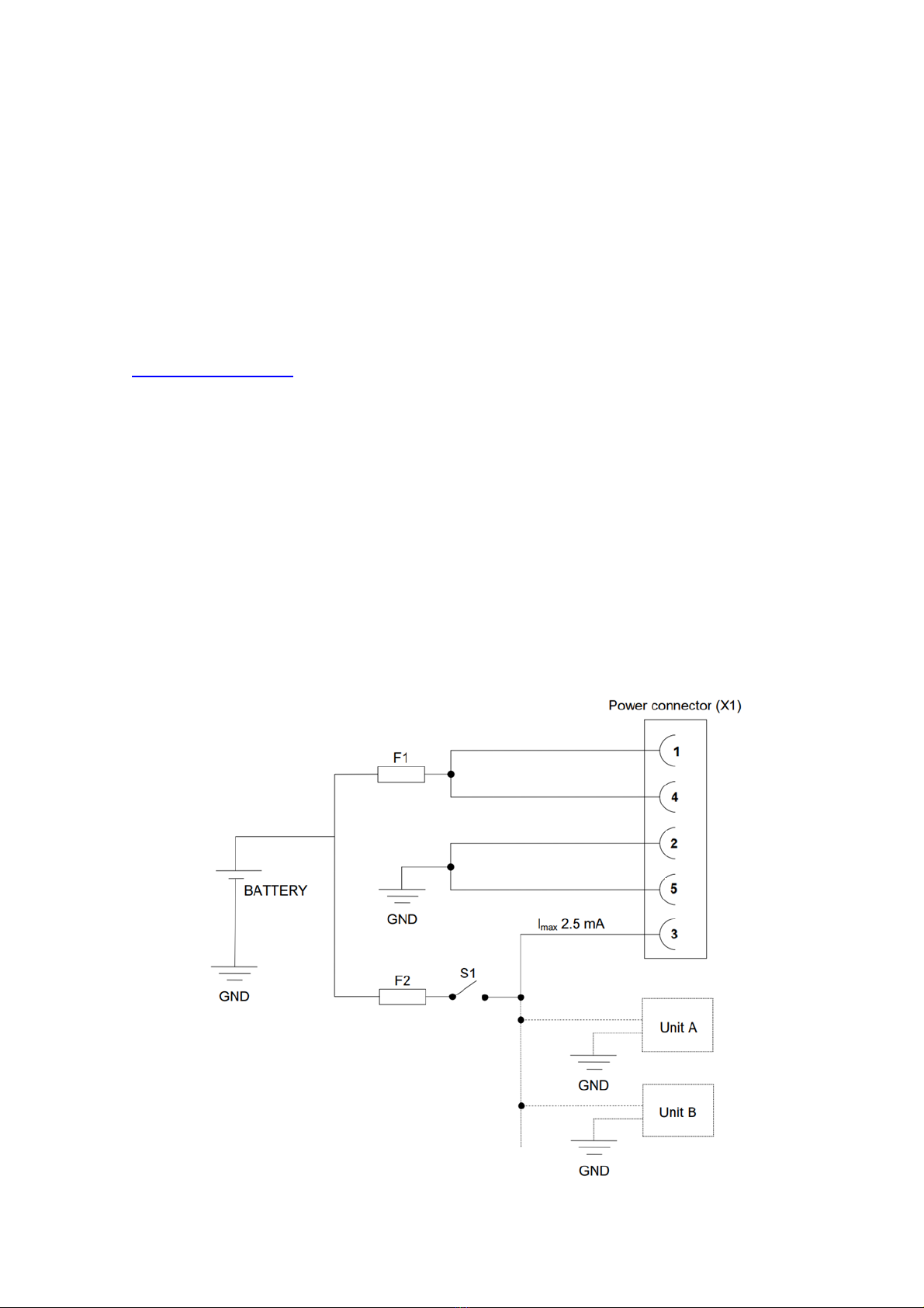
3.1. Connecting to Power Supply ............................................................................................. 7
3.2. Grounding ............................................................................................................................ 8
3.3. Mounting............................................................................................................................... 8
3.4. Environmental Considerations ........................................................................................... 8
3.5. Cable Installation................................................................................................................. 9
4. Basic Operations .................................................................................................................... 10
4.1. Starting Up .......................................................................................................................... 10
4.2. Turning Off........................................................................................................................... 10
4.3. Adjusting the Screen Brightness ....................................................................................... 11
4.4. Using the Touch Screen..................................................................................................... 11
4.5. Status LED Indicators.......................................................................................................... 11
4.6. Clock Back-up Battery ...................................................................................................... 11
5. Interface overview ................................................................................................................. 12
5.1. Storage Memory ................................................................................................................ 12
5.2. Light Sensor......................................................................................................................... 12
5.3. Speaker ............................................................................................................................... 12
5.4. CAN ..................................................................................................................................... 12
5.5. USB ....................................................................................................................................... 12
5.6. Ethernet............................................................................................................................... 13
5.7. Fan Control ......................................................................................................................... 13
6. Connectors ............................................................................................................................. 14
6.1. Connector layout .............................................................................................................. 14
7. Specifications ......................................................................................................................... 16
7.1. Connections ....................................................................................................................... 16
7.2. Technical Data................................................................................................................... 16
7.3. Environmental tolerance .................................................................................................. 17
7.4. Weight and dimensions .................................................................................................... 19
8. Technical Support................................................................................................................... 20
9. Trademarks and terms of use................................................................................................ 21

CCpilot X1400
Product revision: 1.0
Technical manual
2022-12-20
www.crosscontrol.com
3
1. Introduction
CCpilot X1400 is the fifth generation of the CCpilot XL family. A high-performance PC-based
onboard display computer and controller with a rich set of integrated functions. With its powerful 8th
generation Intel® Core i-5 CPU it is an open platform that facilitates easy implementation of
premium user interaction, reliable controls and integrated fleet management. This technical manual
and reference handbook provides important information regarding the hardware and basic usage.
For software and operating system specifics please see additional documentation.
1.1. Product Models
This documentation is applicable for all standard product models of CCpilot X1400.
The platform also enables customization of hardware and software.
1.2. Conventions and Definitions
The ‘exclamation’ symbol -- is used to highlight information that is especially important for the
end-user.
1.3. Identification
On the side of the CCpilot X1400 device there is a label containing version and serial number to
identify your unique computer. Take note of them. During service and other contact with the
supplier it is important to be able to provide this information.
1.4. Maintenance and Care
Handle the device with care and pay attention to the following handling directives:
•Disconnect all cables to the device during welding or when performing other service to the
machine imposing a risk of damaging electronic devices.
•Service and repair to the device shall only be made by authorised personnel. If the device
is opened by unauthorised personnel, its warranty is void.
•Scratches, or even damages, to the display occur easily if it comes in contact with a sharp
object or hard material. In order to increase the longevity of the screen, this should be
avoided.
•The Flash memory used for storage is durable; however as with all flash memory types the
write cycles are limited. Avoid unnecessary writing to the flash memory.
•If the unit becomes too hot it will operate at a limited speed and can also be damaged.
Therefore, do not cover the unit by, for example, hanging a jacket or other clothes on it.
•Consider traffic safety when CCpilot X1400 is installed and whenever it is used.
CrossControl does not recommend that CCpilot X1400 or its accessories is used actively
by the driver when a risk of injury to people, or damage to property, is present.
•Be advised that the device consumes power from the vehicle battery. This can result in the
inability of the vehicle to start if the on-board computer has been on for a period of time
without the vehicle engine running.

CCpilot X1400
Product revision: 1.0
Technical manual
2022-12-20
www.crosscontrol.com
4
1.5. Cleaning
To ensure proper and reliable functionality over time, the unit shall be wiped clean of dirt and dust.
Use a suitable lightly damped cloth to clean the unit.
Never use alkaline, alcoholic, or other chemicals for cleaning which can damage the unit. Never
use high-pressure air, water or steam to clean the device.
1.6. Environment and Environmental Tolerance
The CCpilot X1400 device has been designed to cope with tough environmental demands. Strict
tests have been conducted on the unit in order to ensure that it fulfils the expectations of a rugged
unit. Much work has been performed to choose and design internal components so that they, in the
best possible way, provides you with a dependable and user-friendly working instrument. A full list
of standards to which the device has been tested for compliance can be found in chapter 7 -
Specifications.
The device is preferably placed in a way that prevents exposure to water contact. It is also
important that it is mounted securely on a stand or the like to inhibit the unit from moving and
thereby becoming damaged, damaging the vehicle and/or people during, for example, a traffic
accident.
1.7. Supporting Documentation
This technical manual provides important information regarding the device’s hardware, properties
and basic usage. It is very important to read this manual before installation and usage of the unit.
Not following the instructions around installation, and operation of the unit may lead to reduced
safety of operators and machinery.

CCpilot X1400
Product revision: 1.0
Technical manual
2022-12-20
www.crosscontrol.com
5
2. Device Overview
The CCpilot X1400 is a robust and versatile on-board computer. It is equipped with several
connection options including CAN, Ethernet and USB.
2.1. Front Side
On the front face of CCpilot X1400 there are buttons by default these are for switching the unit
on/off and adjusting the screens brightness level, a speaker, status indicator and a light sensor.
ON/OFF button
Status Indicator
Touch Display
Speaker
Light Sensor
Increase display brightness
Decrease display brightness

CCpilot X1400
Product revision: 1.0
Technical manual
2022-12-20
www.crosscontrol.com
6
2.2. Rear Side
The external connectors are located on the rear side of the CCpilot X1400, they are described in
more detail in chapter 6 - Connectors. There are also mounting holes (M6) for fasteners in
accordance with VESA 75.
Cover for dual CFast memory
Cooling Fan
Mounting holes,
Vesa 75,
4 x M6
3x USB
Ground
M5
GORE-TEX™
Vent membrane
External Connectors
X1
X2
X3
X4
X5
X6
X7
X8
X9
X10
PWR
CAN
CAN
ETH
ETH
USB
USB
USB
FAN
AUDIO

CCpilot X1400
Product revision: 1.0
Technical manual
2022-12-20
www.crosscontrol.com
7
3. Installation
Install the device in such a way that is considered safe and does not expose any unnecessary
stress to the unit. In this section, some recommendations are made regarding installation.
3.1. Connecting to Power Supply
This instruction addresses vehicle installations, but the principle is the same for other types of
installations. See also the description of the pin outs for the Power Supply Connector under
chapter 6 – Connectors.
•Carefully follow the connection instructions below. Make sure that all contacts are angled
correctly and that they do not have to be forced but lock gently and pliant.
•GND (pin 2 and 5) is connected to the vehicle’s ground.
•Battery (pin 1 and 4), i.e. the computer’s power supply (+24 VDC), should be connected
directly to the vehicle’s battery through 10 A fuses (F1). For 12V systems F1 shall be at
least 15A. Wire gauge shall be dimensioned with respect to cable length, supply voltage
etc.
•The ON/OFF (pin 3), i.e. the computer’s on/off signal is connected via the vehicles turnkey
signal or an external on/off switch (S1). If the vehicle has a main power switch the
computer shall be connected after it,. The maximum allowed input current for the on/off
signal is 2.5 mA. The fuse F2 fuse rating and wire gauge shall be dimensioned for the total
switch current.
10/15 A

CCpilot X1400
Product revision: 1.0
Technical manual
2022-12-20
www.crosscontrol.com
8
By connecting the power supply according to the illustration above, the device will automatically
start when the main switch, or turnkey, is turned on, and shut down when the switch, or turnkey, is
turned off. While the main switch is in the ON position, the computer can also be turned off and on
with the On/Off-button. The functionality of the ON/OFF signal and On/Off button can be changed
in software (CCAux API).
3.1.1. Precautions
If applicable, connect the power supply to the device before any main switch, as per the illustration
above. If this is not possible, ensure that the device is turned off using for example the on/off button
or turnkey functionality before turning off the main switch or in any other way making the computer
powerless. Sudden power disruptions may cause the device to shut down, potentially causing lost
or corrupt data. If for example the power fluctuates when starting the vehicle engine, the device
should be started after the vehicle engine is running. Ensure that any application data is saved
before turning off the device. During welding or other service on the machine, all cables to the
CCpilot X1400 shall be disconnected.
3.2. Grounding
Proper grounding minimizes electrical emissions which is why CrossControl recommend grounding
CCpilot X1400 properly using as short and wide ground strap as possible. Attach the ground strap
with a screw next to the ground symbol on the backside of the unit. Use a M5 screw with a
maximum length of 10mm using the same procedure as described in mounting.
3.3. Mounting
CCpilot X1400 can be mounted with a VESA 75 bracket which allows adjustment of the display’s
position and angle. To fasten, use the appropriate M6 cap screw of type MC6S (Allen) or MRT
(Torx). The enclosure has blind holes, which give a maximum thread depth in the enclosure of 10
mm. The maximum torque for 8.8 graded screws is 9.8 Nm. Apply a thread locker in all bolt holes,
e.g. Loctite 222.
3.4. Environmental Considerations
•The device should be placed in a way that prevents the unit from direct exposure to water.
•Use caps on any connectors that do not have attached cables.
•On the back side of the unit is a GORE-TEX® membrane located, visible as a small hole.
This membrane must never be faced upwards when the unit is mounted. Be cautious not to
insert any object into this hole since it can puncture the GORE-TEX® membrane, leaving
the unit unprotected from moisture and dust intrusion. If the membrane is punctured the
guarantee is void.
•To enable sufficient cooling, the device must be installed so that air is able to circulate
around the device, avoid installing the device near hot air vents or the like. There must be
at least 50 mm free distance around the unit.
•Loose mounting bolts are the most common reason for excessive vibration. Mounting bolts
may become loose due to improper techniques such as missing lock washers, over
tightening or under tightening. Proper tightening requires clean dry bolts, and a torque
wrench.

CCpilot X1400
Product revision: 1.0
Technical manual
2022-12-20
www.crosscontrol.com
9
•When CCpilot X1400 or any other device is installed in a vehicle environment it is
important that the installation is traffic-safe. CrossControl does not recommend that CCpilot
X1400 or its accessories are used actively by the driver or operator when a risk of injury to
people, or damage to property, is present.
3.5. Cable Installation
Cables shall be installed in such a way that they do not run any risk of being damaged, pinched or
worn.
•Avoid bending and twisting cables
•Strain-relief cables near the connection to the respective unit
•Properly screw the connectors to give good contact and avoid unnecessary strain
•Shielded cables is recommended and in some cases necessary to ensure reliable
communication and appliance with industrial EMC standards.
Through adapter cables, such as those supplied by CrossControl, standard connectors can be
connected to the unit. The installation of these adapter cables should be placed in a protected,
moisture-free space and should be secured as well as strain-relieved.

CCpilot X1400
Product revision: 1.0
Technical manual
2022-12-20
www.crosscontrol.com
10
4. Basic Operations
This section covers basic operation of the device such as start-up and shut-down.
4.1. Starting Up
Start the unit by pressing and releasing the On/Off button or using the turnkey functionality of the
On/Off signal in the power connector. The status indication LED will start flashing indicating that
the unit is starting up. For more information see chapter 3.1 - Connecting to Power Supply.
4.1.1. Preheating
An internal temperature control prevents the device from starting in too cold or hot temperatures.
When starting the unit in extremely low temperatures, by default -25 °C or below, preheating is
activated to warm the unit before continuing the start-up sequence. When the internal temperature
reaches -25 °C the preheating is deactivated, and the unit continues to start up.
Note that preheating consumes energy from the vehicle’s battery. This can result in the vehicle not
starting after prolonged preheating due to a discharged battery.
4.2. Turning Off
There are several ways to turn the device off. The behaviour of the On/Off button and the On/Off
signal through the Power connector can be adjusted in the CCsettings application and using the
CCAux API.
4.2.1. Shutting Down
To ensure that data does not get lost or the flash memory becomes corrupt, it is recommended that
all necessary data shall is saved, and all programs closed before the unit is shut down.
There are three ways to turn off the device:
•By releasing the power connectors On/Off signal, i.e. using the turn key functionality.
•By selecting any of the operating systems shut-down alternatives.
•CCpilot X1400 can also be turned off by pressing the On/Off button on the display for four
seconds and then releasing it. The time can be adjusted in settings and it can also be
disabled so that the unit cannot be shut down using the button, to prevent turning the
computer off accidentally.
When performing any of the above, the device will shut down. The status LED will flash in yellow to
indicate that releasing the On/Off button will result in the unit shutting down.
4.2.2. Forced Shut Down
If the device is not responding, a forced shut down can be performed by pressing and holding the
On/Off button until the computer is turned off. The time for the forced shut down is double the
normal shut down time or a minimum of eight seconds, by default it is set to eight seconds.
Any information which was not saved will be lost when performing a forced shut down. It is not
recommended to use the forced shut down since it immediately shuts down the computer
regardless of the operating system state.

CCpilot X1400
Product revision: 1.0
Technical manual
2022-12-20
www.crosscontrol.com
11
4.3. Adjusting the Screen Brightness
Press the respective brightness button to gradually increase or decrease the CCpilot X1400 display
brightness. The brightness can also be controlled from software, which also allows for automatic
adjustment of the brightness using the light sensor.
4.4. Using the Touch Screen
The CCpilot X1400 display is equipped with touch functionality which gives the opportunity to
provide a very easy-to-use HMI (Human Machine Interface) for the user.
4.4.1. Double and right click on the touch screen
Double click is performed similar to using an external pointing device - by tapping the screen twice
in the same place. Tap and hold the on the touch screen to perform the equivalent to a right click.
4.5. Status LED Indicators
The status LED indicator on the device indicates different device states using colours and flashing
patterns. The LED behaviour can be controlled both by the operating system and by the
applications executing on the device.
4.6. Clock Back-up Battery
Time and date information is stored in a memory sustained by a back-up battery. This battery has a
limited lifetime and must therefore be exchanged at regular intervals. The lifetime of the battery is
approximately 10 years.

CCpilot X1400
Product revision: 1.0
Technical manual
2022-12-20
www.crosscontrol.com
12
5. Interface overview
This section describes the interfaces on the device.
5.1. Storage Memory
A CFast (faster variant of CompactFlash) memory is used for data storage. This makes the device
robust to vibrations which would be a problem if using a rotating hard disc drive.
The CFast module is classified as industrial grade and has both static and dynamic wear levelling
to prevent a premature aging and to ensure the longest lifetime of the CFast, even though it still
has a limited number of write cycles. It is recommended that the amount of writing to storage is
limited within the application. Rather keep information in RAM memory and write larger blocks at
one time instead of frequently writing smaller pieces.
5.2. Light Sensor
A light sensor is placed in the front of the CCpilot X1400. Using this sensor, ambient light levels
can be measured and used for example by software to automatically adjust the screen brightness.
The device software as a built-in option for this.
5.3. Speaker
CCpilot X1400 has one speaker placed on the front side of the unit. The speaker volume is
controllable through the settings application.
5.4. CAN
The device has two CAN FD interfaces according to CAN ISO 11898.
Each of the two CAN connectors may be prepared with a power supply output as an option for
future use. The maximum total load current is specified at 1A.
The CAN channels are over current and short circuit protected. The CAN connectors follow the
CANopen standard.
Note:
Internal CAN bus filters have a capacitance of 200 pF (typ) which deviates from the ISO 11898
standard. This puts limitations on the CAN bus topology considering bus length, number of CAN
nodes etc. when running at high bit-rates (i.e. above 100-250 kbit/s).
5.5. USB
USB ports enable connection of a multitude of devices to the CCpilot X1400 device.
There are three USB 3.0, one double connector and one single connector. The connectors type are
female type-A-SuperSpeed. The USB ports have common mode filters and ESD protection diodes.
There is a power controller protecting the unit from short-circuit and over current conditions on the
USB ports externally. The USB3.0 ports can supply up to 900mA each.
There are also three USB 2.0 connectors, the same connector type as in XL4; USB Mini
connectors integrated to the M12. The USB data signals, from all three ports are connected to a
hub, to share connection to one USB channel. The three USB ports have common mode filter and
ESD protection diodes. It does have thermal protection (shuts off output) and auto-restart after

CCpilot X1400
Product revision: 1.0
Technical manual
2022-12-20
www.crosscontrol.com
13
error detection (both for short-circuit and thermal shut down), no end user mechanical intervention
needed. The USB2.0 ports can supply up to 500mA each.
5.6. Ethernet
The CCpilot X1400 has two Ethernet connections, fully compatible with the 10BASE-T and
100BASETX standards and galvanic isolated (500 VAC or 707 VDC). Shielded cables shall be
used to ensure reliable communication and EMC immunity.
Be aware that connecting the device to a network environment can impose a security threat.
5.7. Fan Control
The fan speed on CCpilot X1400 is controlled by the processor module and ON/OFF is controlled
by the system supervisor.

CCpilot X1400
Product revision: 1.0
Technical manual
2022-12-20
www.crosscontrol.com
14
6.Connectors
All connectors are accessible from the rear side of the unit. The connectors are marked with an X
and a number as well as a short descriptive text, e.g. X6 USB 2.0.
In order to give the CCpilot X1400 its high environmental classification, the unit is equipped with
DIN M12 connectors. CrossControl can provide adapter cables which convert from DIN M12 to
other connector standards.
Use caution and avoid plugging/unplugging of connectors when the computer is on.
Always replace a damaged cable. If the pins become bent or damaged they may not function
correctly, and the on-board computer or other equipment can be damaged.
6.1. Connector layout
Notice that the connector descriptions are those which are located on the unit, not those that the
attached cables shall have in order to mate with them.
X1 - Power Supply Connector
Pin #
Default signal
Comments
DIN M12 x 1
Male, 5-pole
L-coded
1
VIN
Main Power Input
2
GND
GND Supply
3
ON/OFF
ON/OFF Input Signal
4
VIN
Main Power Input
FE (5)
GND
GND Supply
X2, X3 - CAN Connector
Pin #
Default signal
Comments
DIN M12 x 1
Female, 5-pole
A-coded
Rotation 180°
1
CAN Shield
Connected to chassis ground
2
V+
Can be implemented on request
3
CAN_GND
4
CANH
5
CANL
Housing
CAN Shield
X4, X5 - Ethernet Connector
Pin #
Default signal
Comments
DIN M12 x 1
Female, 4-pole
D-coded
Rotation 180°
1
Tx+
2
Rx+
3
Tx-
4
Rx-
Housing
Shield

CCpilot X1400
Product revision: 1.0
Technical manual
2022-12-20
www.crosscontrol.com
15
X6, X7, X8 – USB 2.0 Connector
Pin #
Default signal
Comments
M12 Speedcon
x 1
Female, 5-pole
Mini-B USB
1
Vbus Out
5 V
2
D-
3
D+
4
NC
5
GND
Housing
Shield
X9 - Fan Connector
Pin #
Default signal
Comments
DIN M12 x 1
Female, 4-pole
A-coded
1
V+
12 V, max 200 mA
2
GND
3
FAN RPM PWM Ctrl
(Output)
4
Tachometer
(Input)
X10 - Audio Connector
Pin #
Default signal
Comments
DIN M12 x 1
Female, 8-pole
A-coded
1
Line out R
2
Line out L
3
GND
4
GND
5
NC
Line In R – Implementation on request
6
NC
Line In L – Implementation on request
7
NC
Mic In – Implementation on request
8
NC
X11, X12, X13 – USB 3.0 Connector
Pin #
Default signal
Comments
USB 3.0, Rugged,
Female, Type-A, R/A
1
Vbus
2
D-
3
D+
4
GND
5
SSRX-
6
SSRX+
7
GND
8
SSTX-
9
SSTX+

CCpilot X1400
Product revision: 1.0
Technical manual
2022-12-20
www.crosscontrol.com
16
7. Specifications
The specifications may vary depending on your computer configuration.
7.1. Connections
Interface / Feature
Number of Connections
CAN bus
2
USB 3.0
3
USB 2.0
3
Ethernet
2
Audio
1
Fan
1
7.2. Technical Data
Kernel
Processor
Intel® Core™ i5-8400H, 4x 2.5 GHz
Data storage
64 GB, Industrial grade Cfast
RAM Memory
8 GB, DDR4-2400
Graphics
Intel® HD Graphics 630
Interfaces
CAN (X2, X3)
Type
CAN FD, ISO 11898, (High Speed CAN)
Baud Rate
Configurable 20 kbit/s – 1 Mbit/s.
CAN FD mode – 500 kbit/s / 10 Mbit/s.
Power Output
Optional feature
USB 2.0 (X6, X7, X8)
Type
Host, V 2.0
Speed
480 Mbit/s
Power Output
5 V, max 500 mA, over current and short circuit protected
USB 3.0 (X11, X12, X13)
Type
Host, V 3.0
Speed
5 Gbit/s
Power Output
5 V, max 900 mA, over current and short circuit protected
Ethernet (X4, X5)
Type
According to 10BASE-T and 100BASE-TX standards
Isolation Voltage
500 VAC / 707 VDC
Audio (X10)
Line Out
Stereo (L+R)
Line In
Optional feature

CCpilot X1400
Product revision: 1.0
Technical manual
2022-12-20
www.crosscontrol.com
17
Mic In
Optional feature
HMI
Status LED
Tricolour LED status indicator with configurable behaviour
Software
Operating system
Windows 10
Additional software
CCsettings, CCvideo. API’s are available to access settings, video
and other equipment from software
Display
14.1”
Type
TFT-LCD, 16:10, anti-glare coated
Resolution
1280 x 800
Colour Depth
16.7M
Backlight
LED, 600 cd/m2
Power Supply
Supply Voltage
12 or 24 V nominal, Continuous operation 10V to 34V
Power Consumption
24 V - Max 6 A at peak load. Typical 1,4 A at idle.
12 V - Max 12 A at peak load. Typical 2,5 A at idle.
7.3. Environmental tolerance
Environmental Test
Standard
Dry Heat
IEC 60068-2-2
Operating: +55°C, 24h
Storage: +60°C, 24h
Damp Heat
IEC 60068-2-30
Operation: +25°C / +55°C
>93% RH 6*24h
Cold
IEC 60068-2-1
Operating: -25°C, 24h
Storage: -40°C, 24h
Change of temperature
IEC 60068-2-14
-25°C to +30°C, 5C/min
3hr hold time, 20 cycles
Vibration
IEC 60068-2-64
0,01 g2/Hz 5-200 Hz 3x1h
Shock
IEC 60068-2-29
5 g / 11ms 3x ±1000 bumps
30 g / 6ms 3x ± 3 bumps
EMC Electrical Transient
ISO 13766-1
ISO 7637-2
Pulse:
1. -450 V
2a. +55 V
2b. +20 V
3a. -220 V
3b. +220 V
4. -4 V (12V system)
5.+70 V
EMC Immunity, ESD
ISO 10605
±15 kV air, ±8 kV contact
EMC Immunity, RF
ISO 11452-2
ISO 11452-4
RF electromagnetic field
200-2000 MHz, 100 V/m
Bulk Current Injection
20-250 MHz, 100 mA

CCpilot X1400
Product revision: 1.0
Technical manual
2022-12-20
www.crosscontrol.com
18
EMC Emission
ISO 14982
Radiated
Nar.b.
Bro.b.
MHz
dBμV/m
dBμV/m
30-75
54-44
64-54
75-400
44-55
54-65
400-1000
55
65
Enclosure
EN 60529
IP54
The tests were performed with 24 V power level. The environmental tolerance may be affected by
external factors like mounting and shielded cables etc.
7.3.1. FCC Notice to Users
Users are not permitted to make changes or modify the device in any way. Changes or
modifications not expressly approved by the party responsible for compliance could void the user’s
authority to operate the equipment.

CCpilot X1400
Product revision: 1.0
Technical manual
2022-12-20
www.crosscontrol.com
19
7.4. Weight and dimensions
Description
Comments
Dimensions
408 x 266 x 85 mm
(W x H x D)
Weight
5,5 kg

CCpilot X1400
Product revision: 1.0
Technical manual
2022-12-20
www.crosscontrol.com
20
8. Technical Support
Contact your reseller or supplier for help with possible problems with your device. In order to get
the best help, you should have your device in front of you and be prepared with the following
information before you contact support.
•Part number and serial number of the unit, which you find on the identification label, see
•Date of purchase, which is found on the invoice.
•The conditions and circumstances under which the problem arises.
•Error codes signalled by the status LED
•Possible error messages which are shown.
•Device log files (if possible).
•Information regarding possible external equipment which is connected to the device.
•Additional sources of information are available on the CrossControl support site:
http://support.crosscontrol.com
Table of contents
Other crosscontrol Desktop manuals
Popular Desktop manuals by other brands

Vertiv
Vertiv Cybex SC 920XD Quick installation guide

Lenovo
Lenovo J100 Quick reference guide

RKM
RKM MK06 Setup guide

John Sands
John Sands SEGA SC3000H Users Instructions, Warranty and Registration Form

Compaq
Compaq Armada 7800 6266 T 5000 D 0 1 Maintenance and service guide

Epson
Epson Endeavor WG Setup guide