crosscontrol CCpilot XL User manual

CC Pilot XLII, rev.1.3 100823
CC Pilot™ XL
Sub User Manual and Reference
Handbook for the CC Pilot™ Model XL

User Manual and Reference Handbook for the CC Pilot™ XL
Table of Contents
Introduction.............................................................................................................................................................. 4
Identification........................................................................................................................................................ 4
Care.................................................................................................................................................................... 5
Environment and Environmental Tolerance ........................................................................................................ 5
Cleaning.............................................................................................................................................................. 5
Overview.................................................................................................................................................................. 6
CC Pilot™ XL – Display unit ............................................................................................................................... 6
CC Pilot™ XL – PC unit ...................................................................................................................................... 7
Connecting the Display to the PC unit ................................................................................................................ 7
Connectors ......................................................................................................................................................... 7
Basic operations ...................................................................................................................................................... 8
Function of the Display’s Push-buttons............................................................................................................... 8
Starting Up.......................................................................................................................................................... 8
Starting in the cold .............................................................................................................................................. 8
Shutting-Down .................................................................................................................................................... 8
Touch screen ...................................................................................................................................................... 9
External interface description ................................................................................................................................ 10
Power Supply Connector .................................................................................................................................. 11
USB (USB 1, USB 2, USB 3, USB 4)................................................................................................................ 11
Ethernet (Ethernet) ........................................................................................................................................... 12
CAN (CAN1, CAN2).......................................................................................................................................... 13
COM ................................................................................................................................................................. 14
DMI - PC ........................................................................................................................................................... 14
DMI - Display .................................................................................................................................................... 15
Audio ................................................................................................................................................................ 16
Video In (Video1, Video2) ................................................................................................................................. 16
VGA Out ........................................................................................................................................................... 17
Installation ............................................................................................................................................................. 18
Placing and installing of the unit and peripherals.............................................................................................. 18
Mounting the PC unit separately....................................................................................................................... 18
Mounting the display......................................................................................................................................... 19
Integrated installation, PC unit mounted on display unit ................................................................................... 19
Mounting Cables............................................................................................................................................... 19
Hook up of Power Supply ................................................................................................................................. 20
Heating via Preheating ..................................................................................................................................... 21
Software ................................................................................................................................................................ 22
Operating System ............................................................................................................................................. 22
CCP settings..................................................................................................................................................... 22
Specifications ........................................................................................................................................................ 24
Computer Core ................................................................................................................................................. 24
2

User Manual and Reference Handbook for the CC Pilot™ XL
Power Supply.................................................................................................................................................... 25
Display.............................................................................................................................................................. 25
Environmental Tolerance .................................................................................................................................. 25
Weight and Dimensions .................................................................................................................................... 26
Contact Technical Support .................................................................................................................................... 29
Trade Mark, etc. .................................................................................................................................................... 30
Index...................................................................................................................................................................... 31
3
User Manual and Reference Handbook for the CC Pilot™ XL
CC Pilot™ XL
Introduction
In this user manual and reference handbook you, as a user, a reseller or system
integrator, will find important information about the CC Pilot™ XL. The handbook will
guide you and broaden your knowledge about this onboard computer’s technical
possibilities and advantages. Described herein are the possibilities which can be
obtained using CC Pilot™ XL in its standard configuration, but we also want to raise
your awareness of the possibility we have to offer specific customized solutions within
the framework of the platform on which CC Pilot™ XL is built.
This material is copyright protected © 2006 CrossControl. All rights reserved.
Identification
There is a brand label on the back of the display and PC-unit of CC Pilot™ XL. On the
brand label there are numbers which identify your unique computer. During service and
other contact with the supplier it is important to be able to provide these numbers.
Brand Label
4

User Manual and Reference Handbook for the CC Pilot™ XL
Care All cables shall be disconnected from your CC Pilot™ XL during welding
or other service on the machine where it is installed.
The CC Pilot™ XL shall only be mounted and serviced by authorised
personnel. If the unit is opened by unauthorised personnel, the normal
guarantee will cease to be valid.
Scratches, or in the worst case damages, to the display occur easily if it
comes in contact with a sharp edge or hard material. In order to increase
the longevity of the screen, this is naturally something which should be
avoided.
The unit can be damaged if it becomes too hot. Therefore, do not cover
the unit by laying things on it, for example hanging a jacket or other
clothes on it.
Consider traffic safety when the CC Pilot™ XL is installed and whenever it
is used. CrossControl does not recommend that CC Pilot™ XL or its
accessories be used actively by the driver when a risk of injury to people,
or damage to property, is present.
Be advised that CC Pilot™ XL draws power from the vehicle battery. This
can result in the inability of the vehicle to start if the onboard computer
has been on for a period of time without the vehicle motor running.
Environment and Environmental Tolerance
The CC Pilot™ XL has been designed to cope with tough environmental demands.
Strict tests have been conducted on the unit in order to ensure that it fulfils the
expectations of a rugged unit. Much work has been performed to choose and design
internal components so that they, under all circumstances and in the best possible way,
provide you with a dependable and user-friendly working instrument. Whithin the
chapter Specifications, a list of standards can be found according to which the CC
Pilot™ XL has been tested and approved.
The CC Pilot™ XL shall preferably be placed under a roof in order to prevent exposure
to direct water contact. It is also important that it is mounted securely on a stand or the
like to inhibit the unit from moving and thereby becoming damaged, damaging the
vehicle and/or people during, for example, a traffic accident.
Cleaning
To ensure proper and reliable functionality over time, the unit shall be wiped cleaned of
dirt and dust. Use a suitable light damp rag to clean the unit.
Never use alkaline, alcoholic or other chemicals for cleaning which can damage the
unit.
5
User Manual and Reference Handbook for the CC Pilot™ XL
CC Pilot™ XL
Overview
The CC Pilot™ XL is a compact, robust and versatile onboard computer. It is equipped
with, among other things, a pressure-sensitive touch screen as well as a large number
of connection alternatives such as CAN, COM, Ethernet and USB.
The CC Pilot™ XL can be delivered in several configurations. This manual will cover the
basic configuration.
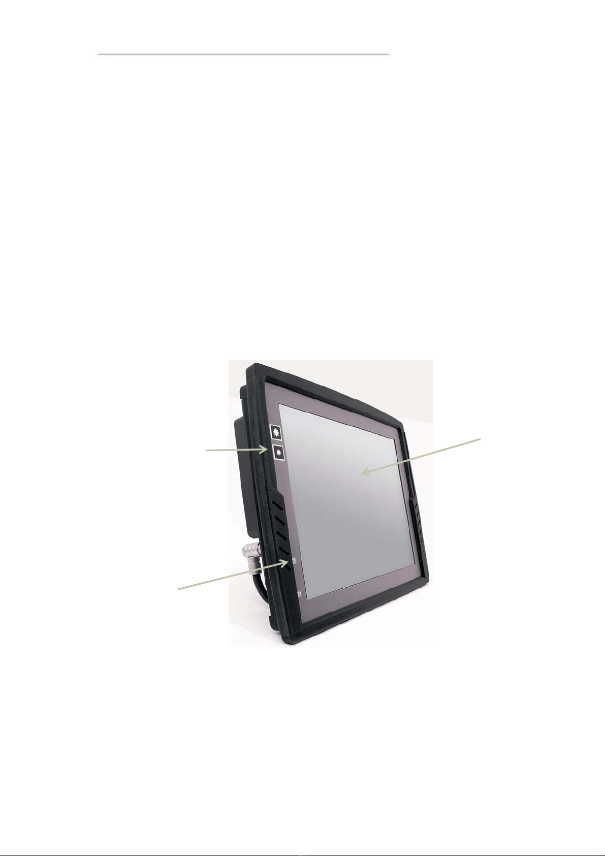
CC Pilot™ XL – Display unit
On the display unit of the CC Pilot™ XL there are buttons for adjusting the screens
brightness level and a status indicator. Depending on the configuration of the display it may
also be equipped with a touch screen.
Touch screen
Increase and decrease
the display’s brightness
level
Status Indicator
6
User Manual and Reference Handbook for the CC Pilot™ XL
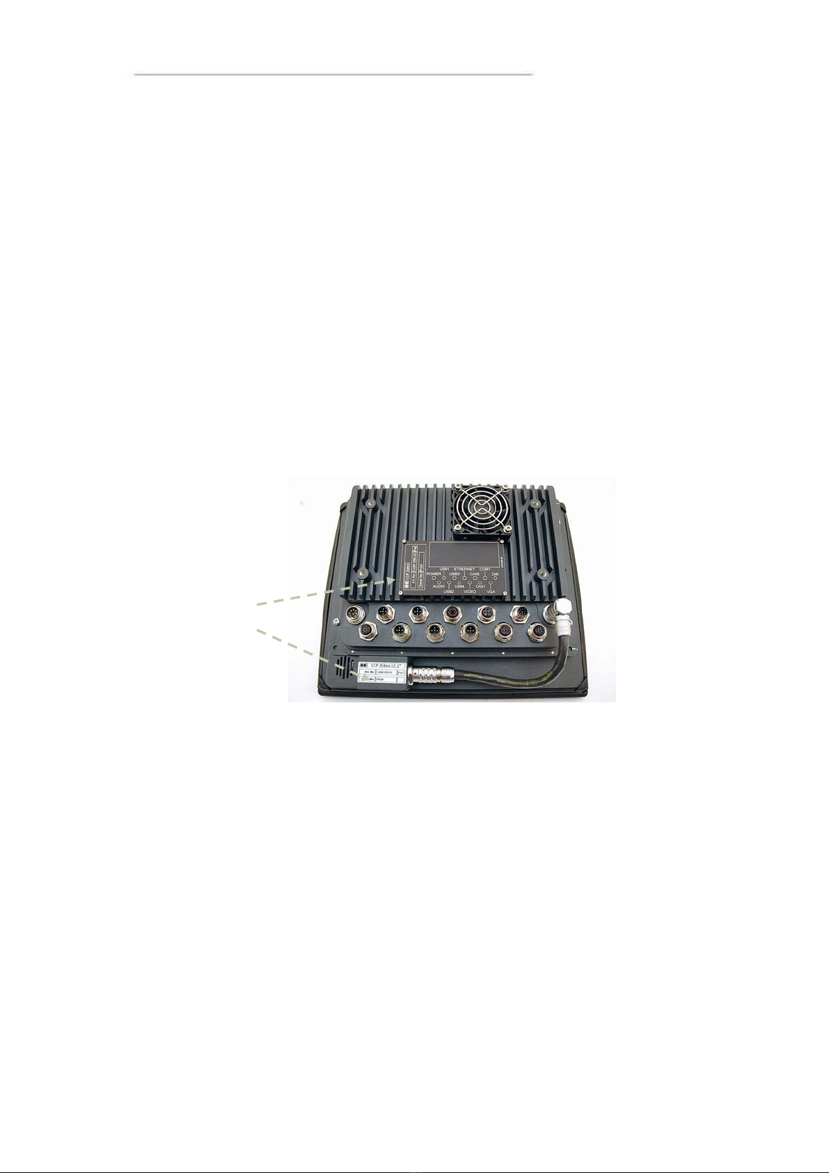
CC Pilot™ XL – PC unit
CC Pilot™ also consists of a PC-unit which contains a hard disk and processor. It also
provides easily accessible external connectors.
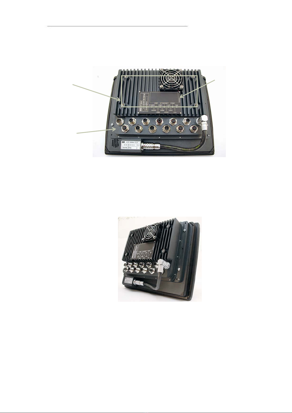
Brand Label &
Connector legend
Mounting Holes
Connecting the Display to the PC unit
The display unit is connected to the PC unit with a (DMI) cable. The units can be
mounted separately or, if combined with a 12.1” display, as an integrated unit, as
shown in the illustration below. The PC unit can also be adjusted to work without the
display unit.
Connectors
The connectors on the CC Pilot™ XL are M12 connectors, except from the display and
power supply connectors. To be able to use connectors from standard peripherals,
adapter cables are available. For more information about see the chapter External
interface description. For more information on installing and setting up CC Pilot™ XL
see chapter Installation.
External connectors
7

User Manual and Reference Handbook for the CC Pilot™ XL
CC Pilot™ XL
Basic operations
This section covers basic operation of the CC Pilot™XL unit such as start-up
and shut down.
Function of the Display’s Push-buttons
In the top left of the CC Pilot™ XL there are two buttons to control the screen
brightness. Press and hold the button to gradually increase or decrease the display’s
brightness.
Starting Up
The unit is started by sending a short push signal to the ON/OFF pins in the power
connector on CC Pilot™ XL. For more information see the chapter Hook up of Power
Supply.
Starting in the cold
Rotating harddrives should not be in used in low temperature. To prevent damage, the
temperature of the harddrive is checked and if needed warmed before start up of CC
Pilot™ XL.
When sending the ON/OFF signal and the temperature is lower than +5°C (+41°F). Your
CC Pilot™ will not start immediately. Instead, an internal heater will warm up the harddrive.
During warm up the LED on the display’s will flash and the display will be activated.
Once the temperature for the hard disk is above +5°C, the CC Pilot™ will start
automatically. The heater continiues to warm the harddrive until it reaches +14°C.
To prepare for a fast start up in low temperatures preheating can be used. For more
information see chapter,
Heating via Preheating.
Values for the temperatures mentioned text are default values but can be changed
from the CCP Settings program.
Shutting-Down
To ensure that data does not get lost or the hard disk become corrupt, it is
recommended that all programs are closed before the unit is shut down.
CC Pilot™ XL can be shut down either from the operative system or from a short push
signal on the ON/OFF input in the power connector.
Forced Shut Down
Setting the ON/OFF signal high for 5 seconds will perform a forced shut down off the
onboard computer. The forced shut down is a direct shut down of the computer without
the control of the the operative system. This shut down should normally be avoided and
only be used when the computer is not responding to normal shut down.
Note that any information which was not saved will now be lost.
8

User Manual and Reference Handbook for the CC Pilot™ XL
Touch screen
The CC Pilot™ XL can as an option be fitted with a touch screen which gives the
opportunity to provide a very easy-to-use HMI (Human Machine Interface) for the user.
Double and right click on the touch screen
To perform the equivalent to a right click on the touch screen first tap the place where
the right click is supposed to be pressed and then tap the screen again slightly to the
side of the initial tap.
To perform a double click on the touch screen, tap the screen twice in the same place.
Calibration of touch screen
If needed the touch screen can be calibrated. Calibration is started manually via the
CCP Settings application. To keep the calibration data the administrator login must be
done in CCP Settings.
Be thorough with this calibration so that your touch screen will have the best possible
performance. You should use the same object (finger, stylus) during calibration which
you think you will use later.
Don’t use sharp or pointed objects on the touch screen since these can damage or
scratch it, which can seriously degrade its functionality.
9

User Manual and Reference Handbook for the CC Pilot™ XL
CC Pilot™ XL
External interface description
Accessible on the rear of CC Pilot™ XL, there are a number of ports to connect various
peripheral equipments. In order to give the CC Pilot™ XL its high environmental
classification, the unit is equipped with DIN M12 connectors. CrossControl provides
adapter cables which convert from DIN M12 to standard connectors.
Use caution and avoid plugging/unplugging of connectors when the computer is on. If
the pins become bent or damaged they may not function correctly, or in the worst case,
the onboard computer or other equipment may be damaged.
The connector legend describes where the connectors are located on your unit. The
connectors available is dependent on the unit’s configuration, therefore connections
can be addressed which may not be available to your unit
Notice that the following connector descriptions are those which are located on the unit,
not those that the attached cables shall have in order to mate with them.
Position Description
X1 Power Supply
X2 Audio
X3 USB 1
X4 USB 2
X5 USB 3
X6 USB 4
X7 Ethernet
X8 Video In
X9 CAN 2
X10 CAN 1
X11 COM
X12 VGA out
X13 DMI
10

User Manual and Reference Handbook for the CC Pilot™ XL
Power Supply Connector
Marking: POWER IN
Connector Type: Serial 723 8 Pin, male
Pin Signal Description Comments
1 NC Not connected
2 Don PC on 10-36 V = PC on
3 Dpow Unswitched
4 Preheating Signal to starts preheating of HD
5 Don PC on 10-36 V = PC on
6 GND Ground
7 Dpow Unswitched
8 GND Ground
The CC Pilot™ XL is primary designed for 24 voltage systems but the power supply
can range from 10 – 36 volts. If the power supply voltage goes beyond this range, the
unit shuts down.
For complete hook up instructions, see the section entitled Installation.
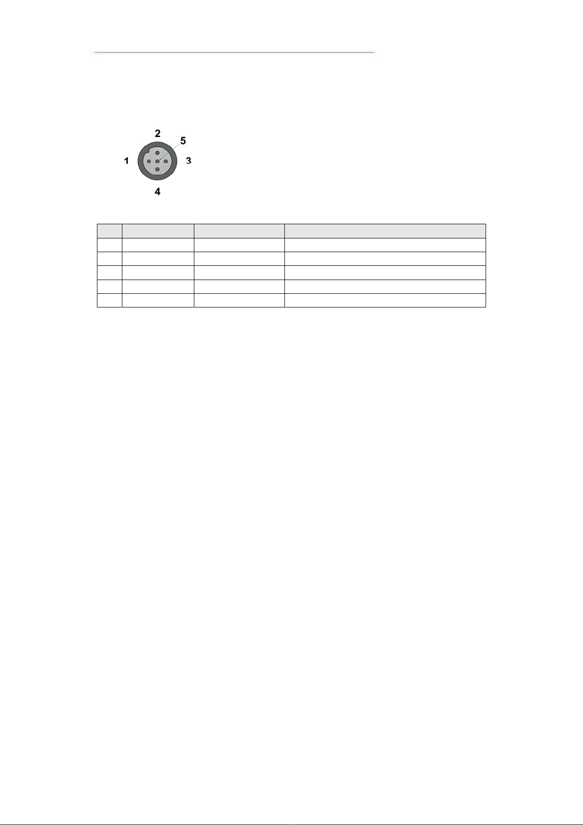
USB (USB 1, USB 2, USB 3, USB 4)
Marking: USB 1, USB 2, USB 3 and USB 4
Connector Type: DIN M12, 5-pole, A-coded, male
Pin Signal Description Comments
1 Vbus Power to external
USB-unit
5 Volt, max 2A for USB 1 and max 500 mA
for USB 2-4. Internal over current and
shortcut protected.
2 D- Data
3 D+ Data
4 NC Not connected
5 GND Ground reference
Via the USB port, you can connect a multitude of devices to the CC Pilot™ XL. For
some devices, drivers compatible with the operating system are required to be installed
in order for the device to function.
11

User Manual and Reference Handbook for the CC Pilot™ XL
The USB ports follow the USB 2.0 standard. Due to data communication safety in
rough environments three of the four available USB connectors is limited to full speed
(up to 12 Mbps). If high speed is necessary (up to 480 Mbps) the device must be
connected to the USB 1.
USB connector 1 can supply up to 2A, USB 2-4 can supply up to 500mA each. The
total current of all USB ports 1-4 has a max of 2A. The USB ports are internal over
current and shortcut protected.
An eventual cable shield is connected to the M12 connectors cover.
Ethernet (Ethernet)
Marking: Ethernet
Connector Type: DIN M12 4-pole, D-coded, female
Pin Signal Description Comments
1 TX+
2 RX+
3 TX-
4 RX-
With an Ethernet connection, the CC Pilot™ XL can access other units and networks.
The Ethernet connector support 10/100 Mbps, i.e. communication speed up to 100
Mbps.
If shielded Ethernet cable is used the cable shield is connected to the M12 connectors
cover.
Be aware that connecting CC Pilot™ XL to a network environment can impose a
security threat.
12
User Manual and Reference Handbook for the CC Pilot™ XL
CAN (CAN1, CAN2)
Marking: CAN 2 and CAN 1
Connector Type: DIN M12, 5-pole A-coded, female
It is possible to connect two CAN-channels to the CC Pilot™ XL to connect a control
system or, for example, the FMS system in a vehicle.
The interface has a PCA82C251 high speed transceiver installed and follows the ISO
11898-24V standard. Alternativley CC Pilot™ XL CAN2 port can be equipped with the
fault tolerant TJA1054AT transceiver.
Pinning of the CAN connector is according to the CANopen standard. The CAN connectors
do not provide power out to external units. There is no termination in the interface; therefore,
this shall be present in the cable.
CrossControl is well-experienced with control via the CAN-interface and both software
and drivers are tested in various environments and under different conditions. Contact
CrossControl if you need more information about our CAN-solutions.
Pin Signal Description Comments
1 CAN1 SHLD
2 NC No connection
3 CAN GND
4 CAN1 H CAN1 High
5 CAN1 L CAN1 Low
13
User Manual and Reference Handbook for the CC Pilot™ XL
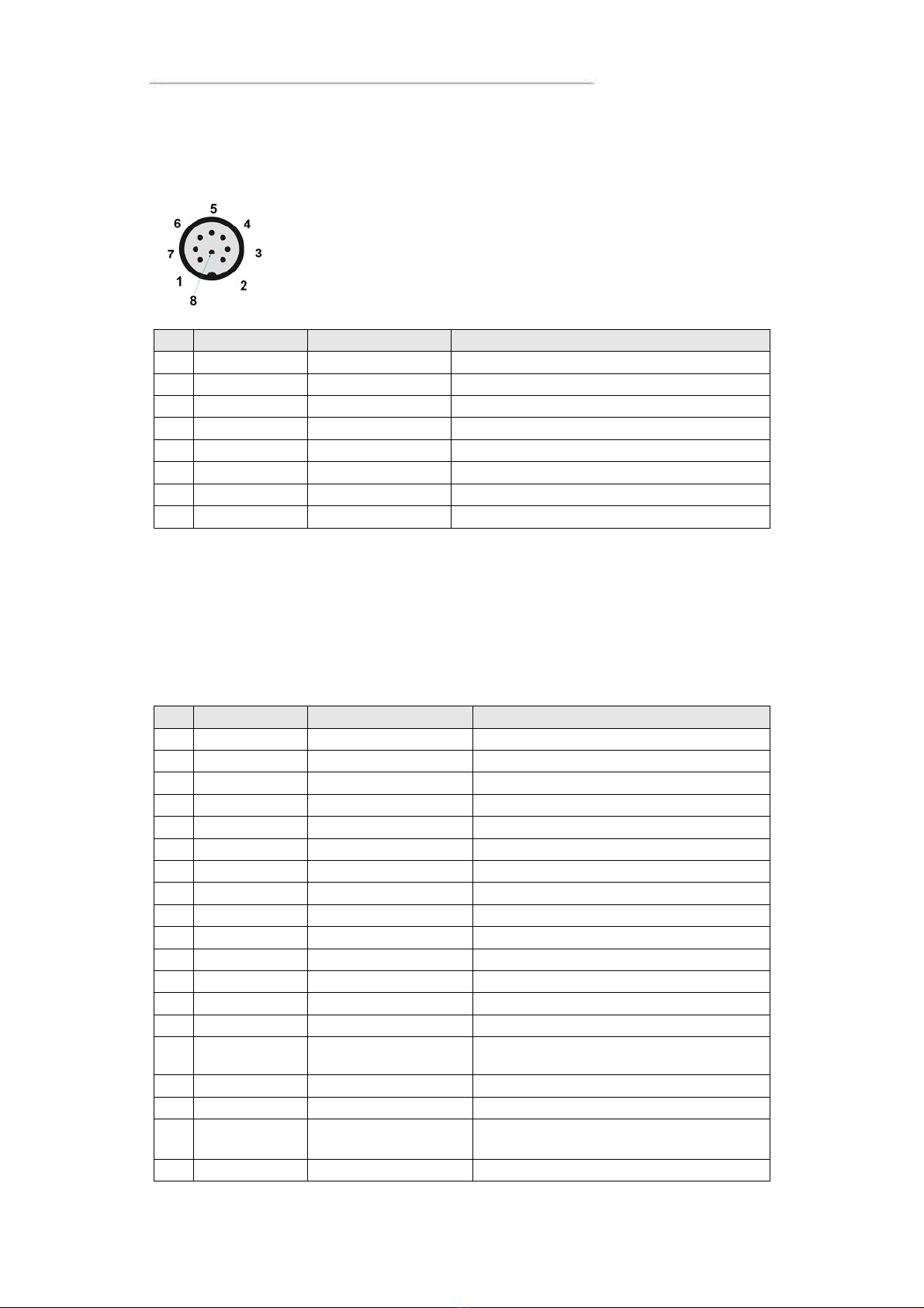
COM
Marking: COM
Connector Type: DIN M12, 8-pole, A-coded, male.
Pin Signal Description Comments
1 DCD Data Carrier
D
2 RxD Receive data
3 TxD Transmit data
4 DTR Data Terminal
Rd
5 GND Signal reference
6 DSR Data Set Ready
7 RTS Request To Send
8 CTS Clear To Send
The COM port follows the RS232 standard except for the “Ring Indicator” signal, which
has been omitted. The supported communication speed for these ports is 2.4 to 115.2
kbps. An eventual cable shield is connected to the M12 connectors cover.
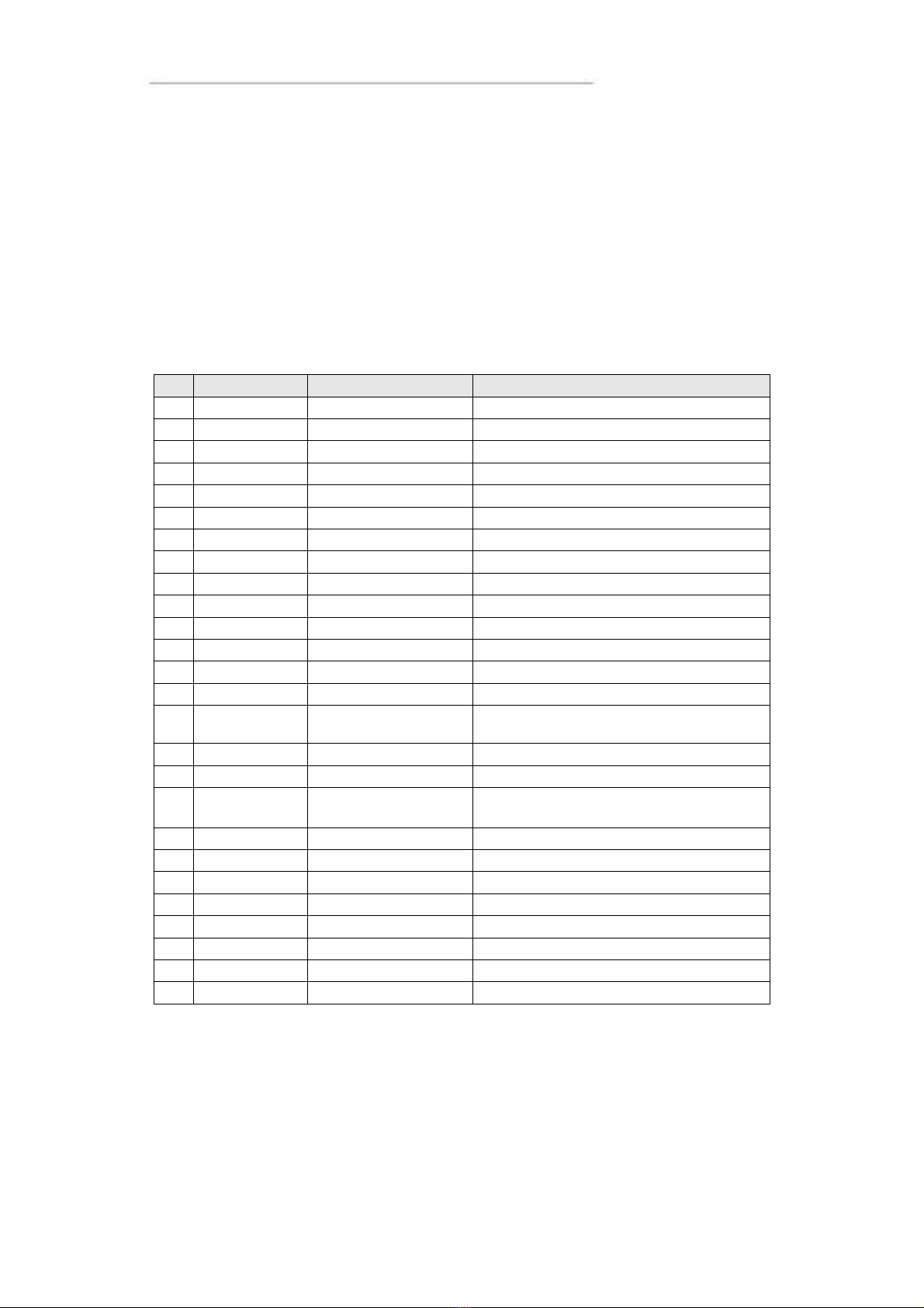
DMI - PC
Marking: DMI
Connector Type: Lemo, female.
Pin Signal Description Comments
1 TXOUT0- LVDS
2 TXOUT0+ LVDS
3 TXOUT1- LVDS
4 TXOUT1+ LVDS
5 TXOUT2- LVDS
6 TXOUT2+ LVDS
7 TXCLK- LVDS
8 TXCLK+ LVDS
9 DMI power
l
+24 V
10 TFT_ON TFT power control
11 Beeper Simple sound unit
12 TS_Tx Touch screen Tx
13 TS_Rx Touch screen Rx
14 SPI_MISO SPI data Display-PC
15 RESET AVR Reset input to AVR Low in, while programming AVR. No
connection in the cable
16 SPI_MOSI SPI data Display-PC
17 SPI_CLK SPI clock Display-PC
18 ON_OFF_2 On/off button from
display to the PC
Not implemented
19 GND Ground reference
14
User Manual and Reference Handbook for the CC Pilot™ XL
The DMI cable handles display and control signals between the CC Pilot™ XL Display and
PC-unit. The maximum recommended DMI cable length is 5.5 m.
Outer cable shield and LCDS double-shield is connected to the connector cover.
For information concerning the DMI connector on the display see chapter DMI -
Display.
DMI - Display
Marking: DMI
Connector Type: Lemo, female.
Pin Signal Description Comments
1 TXOUT0- LVDS
2 TXOUT0+ LVDS
3 TXOUT1- LVDS
4 TXOUT1+ LVDS
5 TXOUT2- LVDS
6 TXOUT2+ LVDS
7 TXCLK- LVDS
8 TXCLK+ LVDS
9 DMI power
l
+24 V
10 TFT_ON TFT power control
11 Beeper Simple sound unit
12 TS_Tx Touch screen Tx
13 TS_Rx Touch screen Rx
14 SPI_MISO SPI data Display-PC
15 RESET AVR Reset input to AVR Low in, while programming AVR. No
connection in the cable
16 SPI_MOSI SPI data Display-PC
17 SPI_CLK SPI clock Display-PC
18 ON_OFF_2 On/off button from
display to the PC
Not implemented
19 GND Ground reference
20 VGA R VGA Red
21 VGA G VGA Green
22 VGA B VGA Blue
23 H Sync Horizontal Sync
24 V Sync Vertical Sync
25 VGA enable Put to gnd when enabled
26 GND VGA Ground reference
The DMI cable handles display and control signals between the CC Pilot™ XL Display and
PC-unit. The maximum recommended DMI cable length is 5.5 m.
Outer cable shield and LCDS double-shield is connected to the connector cover.
For information concerning the DMI connector on the PC unit see chapter DMI - PC.
15
User Manual and Reference Handbook for the CC Pilot™ XL
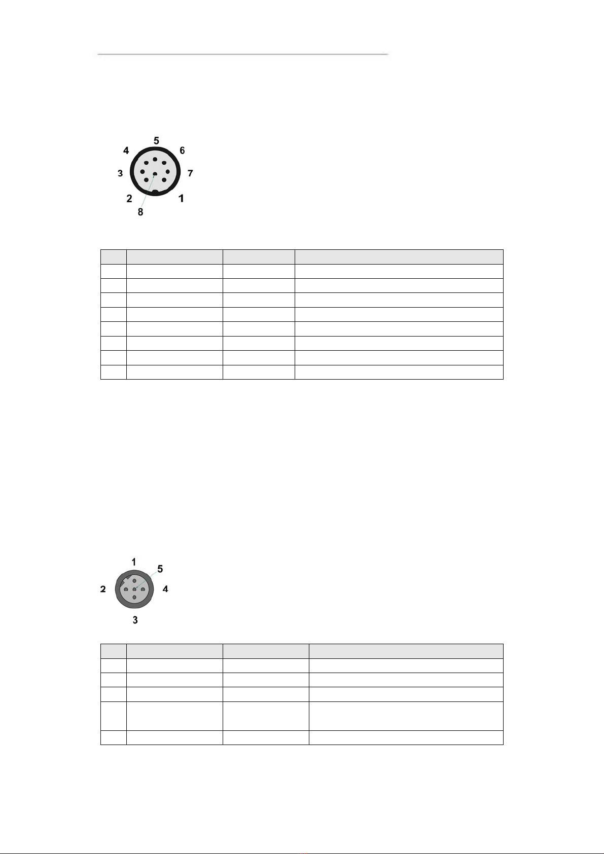
Audio
Marking: Audio
Connector Type: DIN M12, 8-pole, A-coded, female.
Pin Signal Description Comments
1 Line out L
2 Line out R
3 GND (Speaker) Shield in cable
4 Microphone
5 Mic. Ref. Microphone reference
6 Speaker output L Amplified
7 Speaker output R Amplified
8 GND (Line out) Shield in cable
The audio offers possibilities to play everything from warning sounds to music directly
from CC Pilot™ XL two channel speaker stereo output. The output offers both line out
signal and amplified speaker out. Microphone in is also available for sound recording or
to present the sound from, for example, cameras.
Volume is set by the volume controls within Windows.
Video In (Video1, Video2)
Marking: VIDEO
Connector Type: DIN M12, 5-pole, B-coded, male.
Pin Signal Description Comments
1 GND GND Video A
2 Video A PAL/NTSC input
A
3 Video B PAL/NTSC input
B
4 12V_OUT Power out +12 V Power supply to video camera, Max 300
mA
5 GND GND Video B
16
User Manual and Reference Handbook for the CC Pilot™ XL
The Video connector has two composite video inputs for the attachment of video
sources such as rear view cameras. It supports PAL, the European video format, as
well as NTSC-, the American standard.
The video connector can be used to power external using the 12V unfiltered supply.
The output has a current limit that depends on the internal unit temperature. The current is
limited to 0.150A at an internal unit temperature of 70 degrees Celsius and around 0.2A in
normal working conditions.
The cable which is used to connect the camera to the computer shall be a 75-Ωcoaxial
cable, e.g. M17/94-RG179. An eventual outer cable shield is connected to the M12
connectors cover.
Ensure that there is no DC-offset (supply current) on the video signal connected since
this can cause damage to your CC Pilot™ XL.
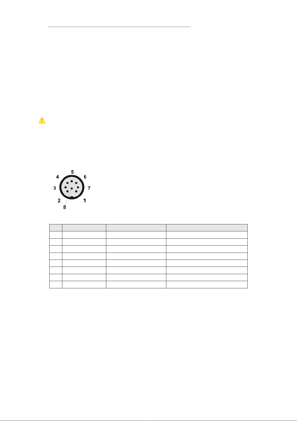
VGA Out
Marking: VGA
Connector Type: DIN M12, 8-pole, A-coded, female.
Pin Signal Description Comments
1 VGA R VGA Red
2 VGA G VGA Green
3 VGA B VGA Blue
4 H Sync Horizontal Sync
5 V Sync Vertical Sync
6 GND R Ground reference Red Shield on VGA Red cable
7 GND G Ground reference Green Shield on VGA Green cable
8 GND B Ground reference Blue Shield on VGA Blue cable
The VGA out can be used as external displays to the CC Pilot™ XL PC unit, either as a
stand alone head display or as dual display together with the CC Pilot™ XL display.
Outer cable shield is connected to the cable connector cover.
17

User Manual and Reference Handbook for the CC Pilot™ XL
CC Pilot™ XL
Installation
Your CC Pilot™ XL must be installed in such a way that the unit is not exposed to any
unnecessary stress or present any traffic danger. In this section, some
recommendations are made regarding methods for how the unit should be installed.
For information about mounting accessories please contact your CC Pilot™ XL
reseller.
CC Pilot™ XL shall only be installed and serviced by authorized personnel. If the unit is
opened by non-authorised personnel, the warranty becomes void.
For the warranty to be valid, the installation of the CC Pilot™ XL must be approved by
CrossControl. This is done through an “Application Approval”; contact CrossControl for
more information.
Placing and installing of the unit and peripherals
The CC Pilot™ XL shall be installed in a ventilated space where air is able to circulate
around the unit, therefore not near hot air vents or the like. There must be at least 50
mm distance between the unit and the closest partition or any other barrier. If the unit
becomes too warm, it may not perform to its full capacity and, with high temperature,
cease to function.
If the preceding instructions are not observed, the cooling of the unit can be degraded
which can lead to overheating, consequently causing permanent damage to the unit.
When the CC Pilot™ XL or any device is installed in a vehicle environment it is
important that the installation is traffic-safe. One should also avoid installing the unit
where it will block the driver’s view. This applies to both the instrument panel and the
view through windshield. One should also think about how the placement affects
personal safety in the event of a collision.
Consider traffic safety whenever the CC Pilot™ XL is installed and used in vehicle
installations. CrossControl does not recommend that the CC Pilot™ XL or its
accessories are used actively by the driver or operator when a risk of injury to people,
or damage to property, is present.
Mounting the PC unit separately
The PC unit should be fastened onto suitable panelling in the cabin or some place
similar. This is done with the six mounting holes on the sides of the unit. Suitable
fasteners, such as MRT M4x25 or MC6S M4x25 screws, can be used. The maximum
tightening torque allowed is 1.0 Nm. If the surface, on which the PC unit should be
fastened, is not flat, care must be taken so as not to put mechanical tension on the unit
during fastening. This can appropriately be solved by placing suitable spacers between
the PC unit and the surface it is to be fastened on. An alternative solution is to use a
separate, flat mounting plate for the PC unit. This plate is first fastened onto the desired
area with separate screws, or by other means. Use thread lockers in all screw holes,
e.g., Loctite 222.
We recommend installing CC Pilot™ XL in such a way that it is not exposed to
unnecessary vibration or other stress.
18

User Manual and Reference Handbook for the CC Pilot™ XL
Mounting the display
Bracket mount
The CC Pilot™ XL is preferably mounted on a convenient bracket which allows for
adjustment of the display’s position and angle. The bracket should have, or be provided
with, a flat fastening plate to which the unit is bolted. The 10.4” display has mounting holes
according to VESA 75 and the 12.1” display is according to VESA 100, depending on
display size). To fasten, use appropriate M6 cap screw of type MC6S (Allen) or MRT (Torx).
Note that the enclosure has blind holes, which give a maximum thread depth in the
enclosure of 6.5 mm. The maximum torque is 2.5 Nm. Apply a thread locker in all bolt holes,
e.g. Loctite 222.
Panel Mount
With a front-mounted installation, use the rubber mask as a seal against the panel
plate. The unit is locked down by applying clamps which are either fixed to the panel
(recommended) or fixed to the unit through holes for VESA installation.
Integrated installation, PC unit mounted on display unit
An integrated installation can only be carried out on the PC unit together with a 12.1”
display unit.
The same placing demands apply here, as when the units are mounted separately.
Mounting, however, is carried out somewhat differently.
To fasten the PC and display units together, screws of type MC6S (Insex) or MRT
(Torx), M4 x 25, should be used. The maximum tightening torque allowed is 1.0 Nm.
Use thread lockers in all screw holes, e.g., Loctite 222.
The mounting holes on the PC unit’s cooling flanges, are used to screw the integrated
unit onto a flat mounting plate. The mounting holes have M6 dimensions and are blind
holes with a depth of 10 mm. Use screws of the correct length so that they do not hit
the bottom of the mounting holes, and always use thread lockers in all screw holes,
e.g., Loctite 222. Maximum tightening torque allowed is 9.8 Nm.
Note that the mounting plate, which is screwed onto the cooling flanges, should not
cover a large area. This may cause poor cooling of the computer and damage it
permanently.
If the screws used in the mounting holes hit the bottom, it may cause damage to the
unit’s enclosure.
Mounting Cables
Cables shall be installed so that they don’t run the risk of being damaged, pinched or
worn. Avoid bending and twisting cables. Strain-relief on cable assemblies shall be
arranged near the connection to the respective unit. The connectors shall always be
screwed-in securely to give good contact and avoid unnecessary strain.
Through adapter cables, as supplied by CrossControl, standard connectors for
Ethernet, USB and COM can be connected to the unit. The hook up of these adapter
cables can and should be placed in a moisture-free, hidden space and should be
secured and strain-relived.
19
User Manual and Reference Handbook for the CC Pilot™ XL
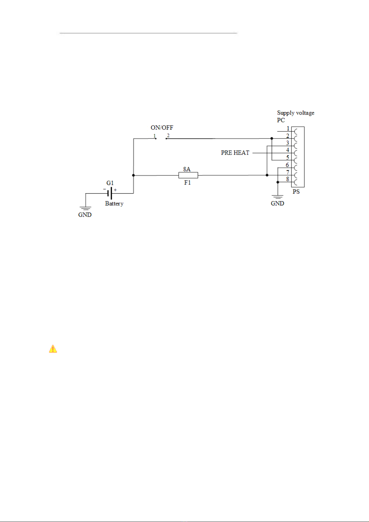
Hook up of Power Supply
This instruction addressed vehicle installations but the principle is the same also for
other types of installations. See also the description of the pin outs for the Power
Supply Connector under the section External interface description.
Carefully follow the connection instructions below. Make sure that the contacts are the right
way up and that they do not have to be forced, but lock gently and pliant.
GND is connected to the vehicle’s ground.
ON/OFF (pins 2 and 5) i.e. the computer’s ON/OFF signal is connected to the battery
or power source through a recoiling ON/OFF button.
Battery (pins 3 and 7), i.e. the computer’s power supply (+24 VDC), should be
connected directly to the vehicle’s battery (G1) through an 8A fuse (F1).
Preheating (pin 4) allows preheating, of the hard disk.
By connecting the power supply according to above, the on-board computer will start
by a short push signal on the ON/OFF button, equal to starting a normal PC computer.
To shut down the CC Pilot™ XL, push the ON/OFF button again or or use the
operating system shut down functionality.
NB! The on-board computer should not be connected so that it is turned on and off
using the ignition key, as this leads to the computer re-starting at an engine failure, for
example.
20
Other manuals for CCpilot XL
1
Table of contents


