Texas Microsystems, Inc. 2003 User manual

2000
SERIES
INDUSTRIAL
COMPUTERS
User Manual
January 1988

<C)
Copyright
Texas
Microsystems,
Inc.
1986
All
rights
reserved.
Trsdemarks:
The
£ollowing
are
trademarks
o£
International
Business
machines:
IBM, AT,
XT
The
in£ormation
in
this
document
is
believed
to
be
accurate.
However,
Texas
Microsystems,
Inc.
does
not
assume
any
liability
£or
inaccuracies
caused
by
human
error,
misinterpretation,
typography,
or
other
causes.
All
equipment
speci£ications
are
subJect
to
change
without
notice.
ii
1.
2.
3.
3.4
4.
5.
TABLE
OF
CONTENTS
GENERAL
DESCRIPTION
••••••••••
1.1
Introduction
•••••••••••••
1.2
Computer
Speci£ications.
1.3
B286
Speci£ications
••••••
CONFIGURATION
AND
INSTALLATION
•••
Rack
Mounting
•••••••••••••••
1
1
1
2
3
3
2.1
2.2
Cable
Connections...........
•
••••
4
2.2.1
Power
Connections
and
Operating
Voltagea
4
2.3
2.2.2
Keyboard
Connections..
•
••••
2.2.3
Monitor
Connections
••••••••
2.2.4
External
Speaker
Jack
•••••••
Installing
Modular
Options
••••••••
2.3.1
Accessing
Modules
in
the
2001
2.3.2
Accessing
Modules
in
the
2003
2.3.3
Accessing
Modules
in
the
2004
2.3.4
Expansion
Slot
Con£iguration
••
2.3.5
Option
Compatibility
••
Computer.
Computer
••
Computer
••
OPER'ATION
•••••••••••••••••••••••••
3.1
3.2
Firmware
Operation
•••••••••••••••••••••••
3.1.1
BIOS
Startup
Routine
••
3.1.2
Setup
Utility
••••••••••••••••••••
3.1.3
Changing
Processor
Clock
Speed.
3.1.4
Continuous
Loop
Diagnostics.
Preparing
the
Hard
Disk
Drive
•••••
3.2.1
Partitioning
the
Hard
Disk
•••••••
3.2.2
Formatting
the
Hard
Disk
••••••••••
3.3
Floppy
Disk
Drives
••••••••••••••••••••••
3.3.1
Compatibility
Guidelines
••••••••••
BASIC
Interpreter........
•••••••••
•
••••••
MAINTENANCE...............
•••••
•
•••••
4.1
4.2
4.3
4.4
Fuses
••••••••••••••••
Fan
Filters
•••••••••••••••••
4.2.1
2001
Computer
Filter
••
4.2.2
2003
Computer
Filter
••••
Replacing
the
B286
Battery
••••
Factory
Return
Goods
Authorizations
.....
(RGA)
•••
MODULES
••••••••••••••••••••••••••••••••
5.1
Central
Processing
Units
(CPUs).
5.1.1
5.1.2
5.1.3
5.1.4
5.1.5
5.1.6
5.1.7
5.1.8
B286
(AT)
CPU
•••••••••
Description
••••.•••••••
Speci£ications
•••••••••••••
Installation
••••••••••
Rev
D
Con£iguration......
•
••••••••••••
Rev
A-C
Con£iguration....
••••••
•
••••
Schematics
£or
rev
D CPU. •
••••••
Schematics
£or
rev
A-C
CPU
••
iii
4
S
S
S
S
6
6
6
7
8
8
9
14
17
17
18
18
19
20
20
21
22
22
22
22
22
23
23
24
24
24
24
24
2S
26
27
27
27
1.
GENERAL
DESCRIPTION
1.1
Introduction
The
2000
series
of
industrial
computers
are
suited
to
a
wide
variety
of
applications
where
durability.
and
ruggedness
are
required
from
a
powerful
IBM
PC
XT/AT
compatible
computer
system.
Factory
automation.
machine
control.
process
control
and
data
acquisition
systems
are
only
a
few
of
these
applications.
Because
the
computers
are
completely
IBM
XT
or
AT
compatible,
they
take
advantage
of
hundreds
of
application
software
packages.
translators,
and
operating
systems.
Hundreds,
possibly
thousands
of
compatible
plug
in
cards
ranging
from
sophisticated
graphics
cards
to
thermocouple
sensors
cards
are
also
available.
This
manual
can
be
used
in
conJunction
with
the
2001A,
2003A
and
2004A
AT
computers
for
configuration
reference,
setup
and
operating
information,
maintenance
procedures.
and
specifications.
1.2
Computer
Specifications
Each
o£
the
computers
have
the
following
features
in
common:
-
IBM
PC/AT
Compatibility
-
Shock
mounted
disk
drives
(in
most
configurations)
-
Passive
backplane
(5,8
bit
and
5,16
bit
slots>
-
Vertically
removable
CPU
card
for
maintenance
-
150
Watt
power
supply
In
addition,
the
2001
computer
is
designed
to
be
mounted
in
a
19
11
RETMA
rack.
It
features
positive
pressure.
filtered
airflow,
a
separate
compartment
for
circuit
cards.
and
up
to
three
shock
mounted
disk
drives.
The
2003
computer
is
a
smaller
benchtop
or
wall
mounted
computer
for
more
specialized
applications.
It
typically
has
a
hard
disk
and/or
one
floppy
disk.
A
portable,
sometimes
used
in
industrial
diskettes.
self
contained
floppy
disk
drive
is
with
this
computer
when
it
is
installed
environments
not
suitable
for
floppy
Preliminary
AT
Users
Manual
1
11/26/86
The
2004
computer
features
NEMA
4
packaging
and
electronics
contained
in
a
sealed
compartment
cooled
by
a
unique
moving
air
heat
exchanger.
1.3
B286
Specifications
The
B286
CPU
is
a
high
performance
IBM
AT
compatible
6
layer
CPU
card
featuring
the
following:
-
Up
to
1
Megabyte
of
parity
checked
DRAM
memory
-
Switchable
clock:
6
and
8
or
optional
6
and
10
MHz
-
On-board
battery
supports
real
time
clock
-
80287
Co-processor
socket
-
Proprietary
Bios
with
built-in
"setup"
program
-
External
reset
switch
and
speaker
Jack
Rather
than
mount
horizontally
in
the the
bottom
of
the
computer.
(as
with
a
typical
motherboard
computer)
the
B286
plugs
into
a
passive
horizontal
motherboard.
If
replacement
is
required,
the
board
can
be
removed
and
replaced
as
easily
as
any
expansion
card.
There
is
no
need
to
disconnect
any
cables
or
remove
any
other
boards.
Preliminary
AT
Users
Manual
2
11/26/86

2.
CONFIGURATION
AND
INSTALLATION
This
section
describes
rack
mounting
of
the
2001
computer,
cabling,
and
expansion
module
installation
and
removal.
2.1
Rack
Mounting
The
2001
computer
and
CRT
display
models
1003R, 1004R,
and
1005R
are
designed
to
be
mounted
in
a
19-inch
RETMA
rack
with
ChassisTrak
300-S-120
slides.
Equivalent
slides
from
other
manufacturers
that
have
matching
hole
spacing
and
alignment
may
also
be
used.
The
steps
for
attaching
slides
to
the
displays
and
the
computer
are
the
same.
Mounting
hardware
is
supplied
with
the.
slides.
9~YI!Q~
DO
NOT
attempt
to
mount
the
computer
or
display
by
attaching
these
units
from
the
front
panel
only.
SLIDE
MOUNTING
INSTRUCTIONS
1.
Two
slides
are
required
for
each
chaasis,
one
on
each
side.
Separate
each
slide
into
two
parts.
2.
Select
the
slide
parts
that
have
a
hole
pattern
matching
the
threaded
holes
on
the
computer.
Using
screws
provided,
attach
a
slide
to
right
and
left
sides
of
the
computer
chassis
(5
screws
on
each
side,
the
spring
loaded
stop
mounts
to
the
rear
of
the
computer).
3.
Attach
the
second
part
of
the
slides
to
the
19-
inch
rack.
Position
the
slides
on
the
left
and
right
sides
of
the
rack
and
screw
each
end
of
the
slide
into
the
rack.
4.
Insert
the
computer
into
the
rack
by
mating
the
computer
slides
with
the
rack
slides.
Make
sure
that
the
computer
is
level
and
properly
aligned
when
it
slides
onto
the
rack.
5.
Push
the
computer
completely
onto
the
rack.
Secure
the
computer
front
panel
into
the
rack
using
4
screws
(8
screws
on
monitors).
6.
Repeat
this
procedure
to
rack
mount
the
CRT
display.
Preliminary
AT
Users
Manual
3
11/26/86
2.2
Cable
Connections
Before
connecting
the
computer
to
a
power
source,
connect
the
CRT
display
and
keyboard
to
the
computer.
If
the
computer
is
to
be
rack
mounted,
refer
to
the
slide
and
rack
mounting
instructions
before
connecting
cables.
2.2.1
Power
Connections
and
Operating
Voltages
The
2001A
rack
mountable
computer
is
capable
of
powering
two
devices
plugged
into
two
external
AC
receptacles
on
the
rear.
The
combined
current
handling
capability
of
the
two
receptacles
is
approximately
6
amps.
The
total
current
drawn
by
a
fully
loaded
unit
including
the
computer
with
a
full
set
of
circuit
cards
and
6
amps
on
external
devices
is
10
amps.
The
2003A
and
2004A
draw
approximately
configured.
computers
are
self
contained
and
4
amps
of
current
when
fully
The
2000
Series
Computers
can
be
modified
at
the
factory
to
operate
using
220-volt
AC
power
or
various
DC
power
voltages.
The
following
considerations
apply
with
this
modification:
l)the
fan
is
replaced
to
operate
properly
with
the
selected
input
power
selected;
2)fuses
are
replaced;
3)the
power
supply
is
Jumper
selected
for
220
volts
or
replaced
with
the
correct
DC
modules.
It
should
be
noted
that
special
considerations
may
be
necessary
to
select
CRT
monitors
for
non
standard
power
situations.
2.2.2
Keyboard
Connections
Both
the
AT
and
XT
keyboard
five-pin
connectors
are
identical
for
all
2000
Series
computers.
The
XT
key-
board
is
specifically
designed
for
the
XT
computer
and
do
••
not
operate
properly
with
an
AT
model.
However,
a
Jumper
.'odification
inside
the
AT
keyboard
allows
it
to
be
downward
compatible
and
to
operate
as
an
XT
keyboard.
Identification
part
numbers
are
placed
on
the
underside
of
each
keyboard.
On
the
2001A
computer,
the
keyboard
connector
is
at
the
lower
left
corner
of
the
front
panel~
For
applications
which
require
it,
a
rear
mounted
keyboard
connector
is
available
as
an
option.
On
the
2003
computer,
the
keyboard
connector
is
at
the
lower
right
corner
at
the
back
of
the
computer.
Preliminary
AT
Users
Manual
4
11/26/86
2.2.3
CRT
Display
Connections
On
the
2001A
computer
the
CRT
display
power
cable
can
be
plugged
into
the
computer
auxiliary
power
outlet.
The
signal
cable
connects
the
Crt
to
the
video
card
connector
at
the
back
o£
the
computer.
When
connected
to
the
auxiliary
outlet,
power
is
supplied
to
the
CRT
display
as
soon
as
the
computer
is
powered-up.
The
2003A
computer
outlets.
There£ore,
plugged
into
a
local
connects
to
the
video
computer.
does
not
have
auxiliary
power
the
display
power
cable
should
be
outlet.
The
display
sig~al
cable
card
connector
at
the
back
o£
the
2.2.4
External
Speaker
Jack
An
external
speaker
Jack
is
standard
on
the
AT
computer
and
optional
on
the
XT
computer.
The
speaker
Jack,
provides
the
capability
£or
audio
output
to
an
external
alarm
or
public
address
system.
The
speaker
Jack
is
located
on
the
CPU
card
at
the
back
o£
the
computer.
2.3
Installing
Modular
Options
The
2000a
Series
Computer
design
provides
£or
easy
access
to
add
or
upgrade
the
system.
Each
computer
is
slightly
di££erent.
The
steps
to
access
cards
£or
each
computer
are
described
in
the
£ollowing
paragraphs.
HQIg
All
captive
nuts
used
in
the
2000
Series
Computers
are
sel£-locking.
Extra
e££ort
may
be
required
to
loosen
or
tighten
the
screws
during
installation.
2.3.1
Accessing
Cards
in
the
2001
Computer
1.
Power-down
the
computer.
2.
Remove
the
3
screws
£rom
the
hinged
access
panel
on
top.
Remove
the
hinged
access
panel
(note
the
position
o£
the
access
panel
hinge
tabs)
and
place
the
screws
and
the
panel
in
a
convenient
place.
3.
Unscrew
and
remove
the
hold-down
clamp
that
£its
across
the
circuit
boards.
4.
To
install
circuit
cards,
instructions
£or
the
card
Section
4).
In
addition,
instructions
that
come
with
Preliminary
AT
Users
Manual
re£er
to
the
speci£ic
to
be
'installed
(see
read
any
installation
the
option
purchased.
5
11/26/86

2.3.2
Accessing
Circuit
Cards
in
the
2003
Computer
1.
Power-down
the
computer.
2.
Remove
the
4
screws
on
each
side
o£
the
top
cover.
Remove
the
top
cover
and
place
the
screws
and
the
cover
in
a
convenient
place.
3.
Unscrew
and
remove
the
hold-down
clamp
that
£its
across
the
circuit
boards.
4.
To
install
circuit
cards,
re£er
to
the
speci£ic
instructions
£or
the
card
to
be
installed
(see
Section
4).
In
addit~on,
read
any
installation
instructions
that
come
with
the
option
purchased.
2.3.3
Accessing
Circuit
Cards
in
the
2004
Computer
1.
Power-down
the
Computer.
2.
Open
the
outer
door.
3.
Unscrew
the
two
thumb
screws
at
the
top
o£
the
inside
chassis.
4.
Insure
adequate
service
loop
is
available
£or
all
cables
and
then
swing
out
(down)
the
inner
chassis.
5.
Unscrew
and
remove
the
hold-down
clamp
that
£its
across
the
circuit
cards.
6.
To
install
circuit
cards,
re£er
to
the
speci£ic
inatructions
£or
the
card
to
be
installed
(see
Section
4).
In
addition,
read
any
installation
instructions
that
come
with
the
option
purchased.
2.3.4
Expansion
Slot
Con£iguration
The
2000
Series
AT
computer
has
£ive
8-bit
and
£ive
16-
bit
expansion
slots.
Viewing
the
back
o£
the
computer,
£rom
right
to
le£t,
expansion
slots
1,
2,
3,
9,
and
10
are
the
8-bits
and
slots
4,
5,
6,
7,
and
8
are
16-bits.
Each
8-bit
slot
has
one
62-pin
connector
providing
8
data
bits
and
20
address
lines.
This
con£iguration
is
equivalent
to
an
address
space
o£
1M
byte
that
is
8
bits
wide.
Each
16-bit
slot
has
two
connectors.
A
62-pin
connec-
tor
contains
the
lower
8
data
bits
and
lower
20
address
lines.
A
36-pin
connector
contains
the
upper
8
data
bits
and
upper
4
address
lines.
The
combined
bus
con-
Preliminary
AT
Users
Manual
6
11/26/86

figuration
has
a
capacity
of
16M
bytes
of
address
space
that
is
16
bits
wide.
The
2000
Series
XT
configuration
has
ten
8-bit
expan-
sion
slots.
Each
slot
has
a
62
pin
connector
that
pro-
vides
8
data
bits
and
20
address
lines.
The
AT
16-bit
expansion
cards
are
slightly
(0.6
inches)
taller
than
the
XT
8-bit
expansion
cards.
To
provide
for
a
hold
down
clamp
that
can
accommodate
the
different
height
boards,
the
AT
cards
are
grouped
together
near
the
center
of
the
expansion
slots
2.3.5
Option
Compatibility
Modular
options
are
added
by
means
of
expansion
cards
that
plug
into
the
computer
bus
(expansion
slots).
This
bus
is
designed
to
be
both
electrically
and
mechanically
compatible
with
the
equivalent
International
Business
Machine
computer
models.
On
the
2000
Series
AT
(6MHz
clock
speed)
and
XT
models,
the
bus
timing
is
identical
to
the
IBM
equivalent.
The
AT
computers,
operating
at
8
or
10
MHz,
have
faster
bus
transfer
rates
and
may
not
be
compatible
with
all
expansion
cards.
Although
XT
8-bit
expansion
cards
may
work
electronically
in
the
AT
16-bit
slots,
the
XT
cards
may
not
be
physically
compatible
because
the
AT
has
the
additional
36
pin
connector.
In
addition,
the
AT
16-
bit
cards
are
not
designed
to
work
in
8-bit
slots.
Expansion
card
compatibility
may
also
vary,
depending
on
the
manufacturer.
Processor
clock
speed
differences
may
also
effect
expansion
card
compatibility.
The
2000
Series,
AT,
80286
processor
operates
at
a
much
faster
speed
(6,
8,
or
10
MHz)
than
the
XT
model
8088
processor
speed
(4.77
MHz).
To
accommodate
this
speed
difference,
the
B286
card
contains
a
programmable
wait
state
generator
which
inserts
additional
time
in
the
bus
transfer
cycles.
Refer
to
the
module
section
for
a
detailed
description
of
this
feature.
For
most
plug
in
modules,
the
additional
wait
states
are
all
that
is
required
for
compatibility.
If
a
speed
problem
is
suspected,
contact
the
manufacturer
of
the
plug
in
circuit
card
regarding
operation
at
the
higher
bus
speeds.
Preliminary
AT
Users
Manual
7
11/26/86
3.
OPERATION
This
section
describes
the
operation
o£
the
computer_
including
a
description
o£
the
BIOS
and
SETUP
£irmware
contained
on
the
B286
CPU.
3.1
Firmware
Operation
The
B286
board
contains
approximately
32k
o£
£irmware
in
two
32K x 8 EPROMS.
This
£irmware
per£orms
power-on
computer
checks,
sets
up
the
computer
hardware,
and
contains
the
internal
setup
routines
£or
con£iguration.
The
computer
can
be
restarted
using
three
methods:
1.
Cycle
the
ON/OFF
power
switch
to
the
ON
position.
2.
Reboot
the
computer
-
Press
and
hold
the
CTRL
and
ALT
keys
and
then
press
the
DELETE
key.
3.
Press
the
RESET
pushbutton
-
the
computer
stops
processing
activities
and
reboots.
This
method
is
only
recommended
as
a
"last
resort"
because
loss
o£
data
can
result
i£
a
program
is
in
process.
The
BIOS
per£orms
internal
diagnostics
to
check
the
current
con£iguration
against
the
con£iguration
in£ormation
recorded
in
CMOS
memory
during
Setup.
1£
inconsistencies
exist,
BIOS
error
messages
are
displayed.
Some
o£
these
errors
can
be
quickly
corrected
by
checking
the
Setup
in£ormation.
More
technical
errors
require
the
assistance
o£
trained
TMI
technical
personnel.
Some
o£
the
elements
tested
during
BIOS
diagnostics
include
the
£ollowing:
Processor
CPU
chip
DMA
controllers
Floppy
disk
drive
controllers
Hard
disk
drive
controller
Hard
disk
drive
con£iguration
Real
time
clock
chip
Interrupt
controller
chip
Keyboard
Time-o£-day
clock
(CMOS
RAM)
Video
controllers
RAM
memory
BIOS
ROM
(check
aum
used
£or
validity)
Although
BIOS
power-up
diagnostics
are
not
comprehensive,
the
£ew
seconds
that
the
BIOS
routine
requires
are
very
e££ective
in
identi£ying
problems.
For
in
depth
diagnostics
that
are
more
comprehensive
and
require
more
time,
the
International
Business
Preliminary
AT
Users
Manual
8
11/26/86
Machines
Advanced
Diagnostics
program
£or
the
AT
can
be
used.
3.1.1
BIOS
Startup
Routine
The
BIOS
is
a
collection
o£
driver
and
initialization
so£tware
stored
in
ROM
on
the
CPU
board.
The
BIOS
is
designed
to
be
totally
compatible
with
so£tware
written
£or
the
IBM
personal
computers.
The
IIO
drivers
are
invoked
through
the
so£tware
interrupt
structure
o£
the
80286
processor.
The
largest
portion
o£
the
BIOS
so£tware
program,
(approximately
4K
bytes),
is
devoted
to
computer
startup.
During
this
procedure,
the
memory
and
IIO
ports
are
tested
and
initialized.
I£
everything
goea
well
and
no
errors
are
discovered,
an
operating
system
is
loaded
and
executed
£rom
the
disk
or
other
mass
storage
device.
The
BIOS
startup
routine
is
as
£ollows:
1.
The
80286
executes
a
Jump
instruction
to
the
BIOS
start
point.
2.
The
CPU
£lags
are
tested.
The
80286
processor
register
set
is
tested.
I£
either
o£
these
tests
£ails,
the
CPU
halts.
3.
Video
controllers
are
stabilized.
4.
The
£ollowing
occurs
during
halts.
tests
are
per£ormed.
I£
a
£ailure
anyone
o£
these
tests,
the
CPU
5.
The
shutdown
byte
in
CMOS
RAM
is
tested
£or
reliability.
6.
The
8254
timer
is
tested.
7.
DMA
controllers
are
tested.
8.
DMA
page
registers
are
tested.
9.
DMA
controllers
are
initialized.
10.
Memory
re£resh
is
tested.
the
CPU
halts.
I£
a
£ailure
occurs,
11.
Bus
A20
line
is
disabled.
Preliminary
AT
Users
Manual
9
11/26/86

12.
The
£irst
64K
bytes
o£
memory
are
tested.
I£
£ailure
occurs,
the
£ollowing
error
message
is
displayed:
oooo:xxxx
yyyy
#201
Where:
x =
Failing
Address
y =
Failing
Data
13.
The
stack
is
set
up.
14.
The
interrupt
controllers
are
initialized.
15.
All
interrupt
vectors
are
set
to
the
temporary
in-
terrupt
handler.
16.
So£tware
interrupt
vectors
are
initialized.
17.
The
8042
keyboard
peripheral
inter£ace
chip
is
tested.
18.
CMOS
memory
is
tested.
19.
Base
memory
size
is
determined.
20.
Video
controllers
are
tested
against
the
CMOS
con-
£iguration.
21.
Video
card
BIOS
ROMs
are
initialized.
22.
Video
cards
are
tested.
1£
the
video
card
tested
does
not
agree
with
the
#1
switch
setting
on
the
CPU
card,
an
audible
beep
is
heard
(one
long
and
two
short
beeps>.
23.
Hardware
interrupt
vectors
are
initialized.
24.
De£ault
power-up
processor
speed
is
selected.
25.
The
monitor
screen
is
cleared
and
the
TMI
logo
is
displayed
with
the
£ollowing
message:
The
TMI INDUSTRIAL
COMPUTER
BIOS
Sel£-Test
in
Progress,
Please
Wait
26.
Keyboard
is
tested.
Prelimin~ry
AT
Users
Manual
10
11/26/86
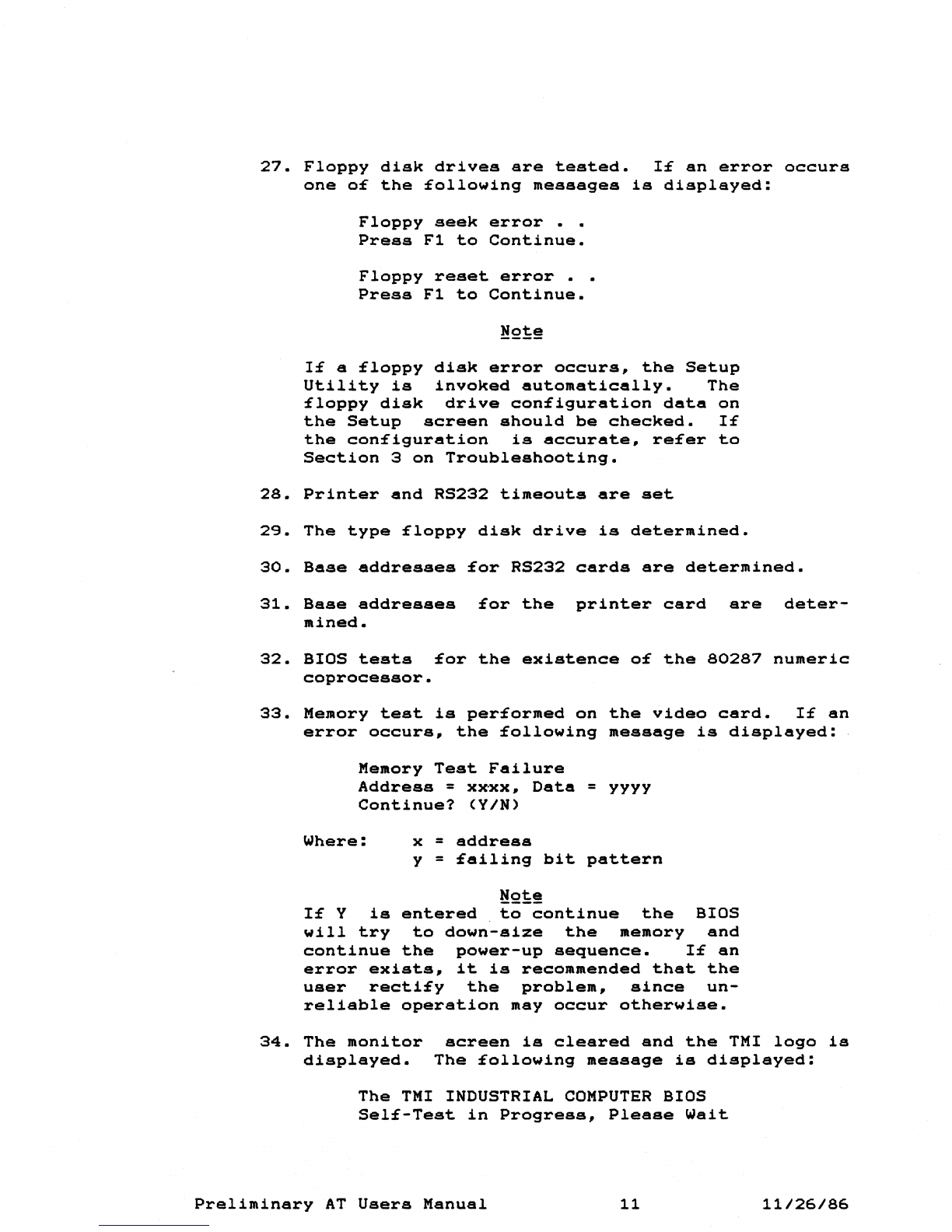
27.
Floppy
disk
drives
are
tested.
If
an
error
occurs
one
o£
the
£ollowing
messages
is
displayed:
Floppy
seek
error
• •
Press
F1
to
Continue.
Floppy
reset
error
• •
Press
F1
to
Continue.
If
a
floppy
disk
error
occurs,
the
Setup
Utility
is
invoked
automatically.
The
floppy
disk
drive
configuration
data
on
the
Setup
screen
should
be
checked.
If
the
con£iguration
is
accurate,
re£er
to
Section
3
on
Troubleshooting.
28.
Printer
and
RS232
timeouts
are
set
29.
The
type
£loppy
disk
drive
is
determined.
30.
Base
addresses
for
RS232
cards
are
determined.
31.
Base
addresses
for
the
printer
card
are
deter-
mined.
32.
BIOS
tests
for
the
existenee
of
the
80287
numeric
coprocessor.
33.
Memory
test
is
performed
on
the
video
card.
If
an
error
occurs,
the
following
message
is
displayed:
Memory
Test
Failure
Address
=
xxxx,
Data
=
yyyy
Continue?
(YIN)
Where:
x =
address
y =
failing
bit
pattern
!'!2!:!
If
Y
is
entered
to
continue
the
BIOS
will
try
to
down-size
the
memory
and
continue
the
power-up
sequence.
If
an
error
exists,
it
is
recommended
that
the
user
rectify
the
problem,
since
un-
reliable
operation
may
occur
otherwise.
34.
The
monitor
displayed.
screen
is
cleared
and
the
TMI
logo
is
The
£ollowing
message
is
displayed:
The
TMI
INDUSTRIAL
COMPUTER
BIOS
Self-Test
in
Progress,
Please
Wait
Preliminary
AT
Users
Manual
11
11/26/86
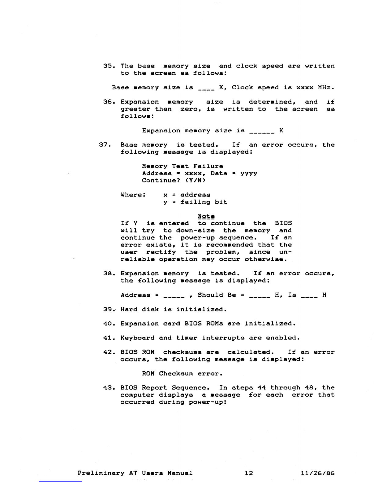
35.
The
base
memory
size
and
clock
speed
are
written
to
the
screen
as
£ollows:
Base
memory
size
is
____
K,
Clock
speed
is
xxxx
MHz.
36.
Expansion
memory
greater
than
zero,
£ollows:
size
is
determined,
and
is
written
to
the
screen
Expansion
memory
size
is
K
i£
as
37.
Base
memory
is
tested.
1£
an
error
occurs,
the
£ollowing
message
is
displayed:
Memory
Test
Failure
Address
=
xxxx,
Data
=
yyyy
Continue?
(YIN)
Where:
x =
address
y =
£ailing
bit
N2~~
1£
Y
is
entered
to
continue
the
BIOS
will
try
to
down-size
the
memory
and
continue
the
power-up
sequence.
1£
an
error
exists,
it
is
recommended
that
the
user
recti£y
the
problem,
since
un-
reliable
operation
may
occur
otherwise.
38.
Expansion
memory
is
tested.
1£
an
error
occurs,
the
£ollowing
message
is
displayed:
Address
=
_____
,
Should
Be
= H,
Is
____
H
39~
Hard
disk
is
initialized.
40.
Expansion
card
BIOS
ROMs
are
initialized.
41.
Keyboard
and
timer
interrupts
are
enabled.
42.
BIOS
ROM
checksums
are
calculated.
1£
an
error
occurs,
the
£ollowing
message
is
displayed:
ROM
Checksum
error.
43.
BIOS
Report
Sequence.
In
steps
44
through
48,
the
computer
displays
a
message
£or
each
error
that
occurred
during
power-up:
Preliminary
AT
Users
Manual
12
11/26/86

44.
Hard
disk
errors;
one
o£
the
following
messages
may
be
displayed:
Hard
disk
controller
Hard
disk
failure
on
Drive
0
Hard
disk
failure
on
drive
1
45.
Memory
size
comparison
errors;
the
following
message
is
displayed:
Invalid
memory
size
con£iguration
46.
CMOS
equipment
configuration
error;
the
following
message
is
displayed:
Invalid
CMOS
equipment
con£iguration.
47.
CMOS
checksum
error;
the
following
message
is
displayed:
CMOS
checksum
is
bad.
48.
Bad
Battery;
the
£ollowing
message
is
displayed:
Bad
battery
£lag
set
in
CMOS.
49.
If
any
of
the
errors
(44
through
48)
occur,
the
Setup
Utility
is
invoked
automatically.
The
configuration
data
on
the
Setup
screen
should
be
checked
for
accuracy.
If
the
con£iguration
is
accurate,
press
F1
to
continue.
50.
BIOS
Report
Sequence.
In
steps
51
through
54,
the
computer
displays
a
message
for
each
error
that
occurred
during
power-up.
Each
message
is
displayed
for
5
seconds
and
then
messages
are
cleared.
51.
Keyboard
error
displayed:
the
£ollowing
message
Keyboard
error
or
keyboard
not
present.
is
52.
Type
Monitor
doesn't
agree
with
switch
setting
on
video
card
-
one
o£
the
following
messages
may
be
displayed:
Display
switch
set
for
color
adapter
Display
switch
set
for
monochrome
adapter
53.
Video
card
horizontal
sync
output
not
present-
the
following
message
is
displayed:
Preliminary
AT
Users
Manual
13
11/26/86
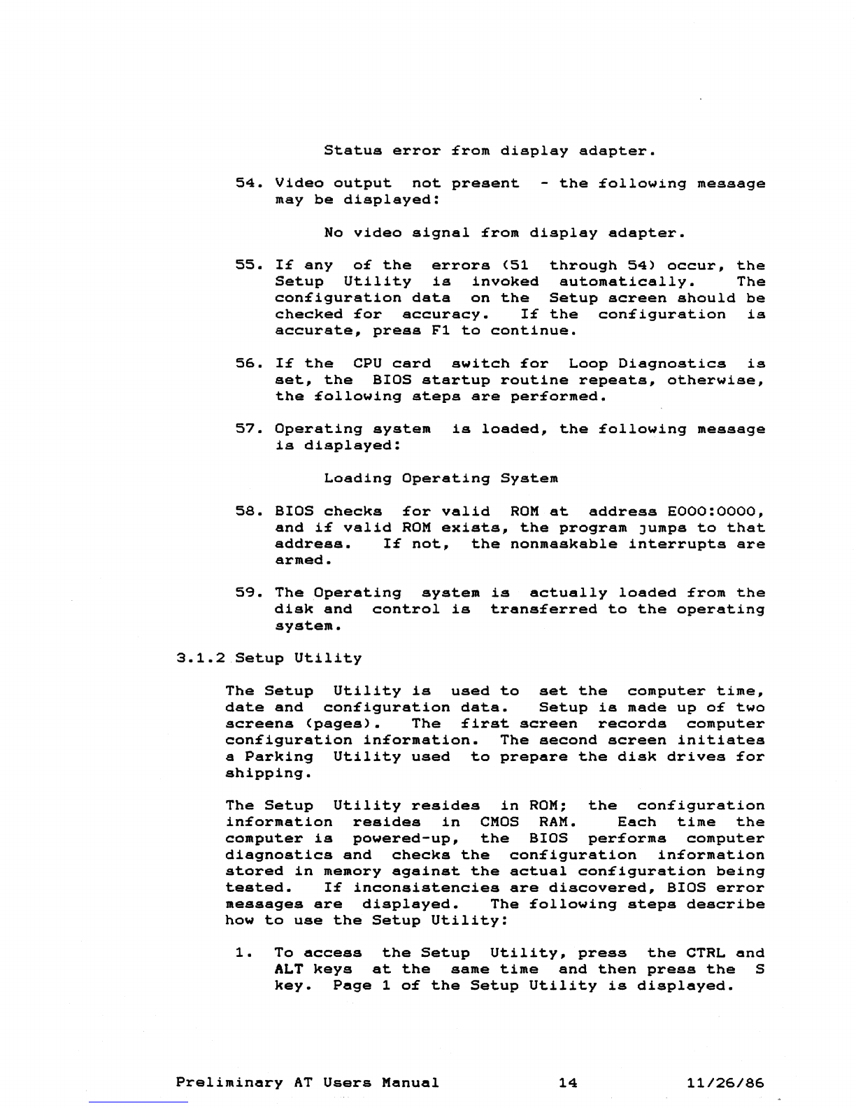
Status
error
£rom
display
adapter.
54.
Video
output
not
present
-
the
£ollowing
message
may
be
displayed:
No
video
signal
£rom
displsy
adapter.
55.
1£
any
o£
the
errors
(51
through
54)
occur.
the
Setup
Utility
is
invoked
automatically.
The
con£iguration
data
on
the
Setup
screen
should
be
checked
£or
accuracy.
1£
the
con£iguration
is
accurate.
press
F1
to
continue.
56.
1£
the
CPU
card
switch
£or
Loop
Diagnostics
is
set.
the
BIOS
startup
routine
repeats.
otherwise.
the
£ollowing
steps
are
per£ormed.
57.
Operating
system
is
loaded.
the
£ollowing
message
is
displayed:
Loading
Operating
System
58.
BIOS
checks
£or
valid
ROM
at
address
EOOO:OOOO.
and
i£
valid
ROM
exists.
the
program
Jumps
to
that
address.
1£
not.
the
nonmaskable
interrupts
are
armed.
59.
The
Operating
system
is
actually
loaded
£rom
the
disk
and
control
is
trans£erred
to
the
operating
system.
3.1.2
Setup
Utility
The
Setup
Utility
is
used
to
set
the
computer
time.
date
and
con£iguration
data.
Setup
is
made
up
o£
two
screens
(pages).
The
£irst
screen
records
computer
con£iguration
in£ormation.
The
second
screen
initiates
a
Parking
Utility
used
to
prepare
the
disk
drives
£or
shipping.
The
Setup
Utility
resides
in
ROM;
the
con£iguration
in£ormation
resides
in
CMOS
RAM.
Each
time
the
computer
is
powered-up.
the
BIOS
per£orms
computer
diagnostics
and
checks
the
con£iguration
in£ormation
stored
in
memory
against
the
actual
con£iguration
being
tested.
1£
inconsistencies
are
discovered.
BIOS
error
messages
are
displayed.
The
£ollowing
steps
describe
how
to
use
the
Setup
Utility:
1.
To
access
the
Setup
Utility.
press
the
CTRL
and
ALT
keys
at
the
same
time
and
then
press
the
S
key.
Page
1
o£
the
Setup
Utility
is
displayed.
Preliminary
AT
Users
Manual
14
11/26/86

2.
Use
the
up
and
down
arrows
to
select
the
desired
field.
Use
the
plus
(~)
and
minus
(-)
keys
on
the
keypad
to
scroll
through
possible
choices.
Time
Sets
the
computer
real
time
clock
(24
hour
format)
Date
Sets
the
computer
date
(mm/dd/yyyy)
Floppy
Disk
Drive
A:
Floppy
Disk
Drive
B:
Hard
Disk
Drive
C:
Hard
Disk
Drive
D:
Monitor
Type
Base
memory
size
Expansion
memory
size
Power-up
Processor
Drive
capacity:
High
Capacity
(1.2M
bytes)~
Double
Sided
(360K
bytes),
3.5-inch
(720K
bytes)
drive.
Drive
capacity:
Double
Sided
(360K
bytes),
High
Capacity
(1.2M
bytes)~
3.5-inch
(720K
bytes)drive.
Drive
type
(Range
1
to
15,
see
table)
or
not
installed
Drive
type
(Range
1
to
15,
see
table)
or
not
installed
Monochrome~
40
Column
Color,
80
Column
Color,
EGA
or
other
Range
from
128K
to
640K
bytes
in
128K
increments
Range
from
OM
to
15M
bytes
in
128K
increments
Options
are:
6~
8,
or
10MHz
3.
After
modifications
are
made,
press
Fl
to
restart
the
computer
from
power-up.
Preliminary
AT
Users
Manual
15
11/26/86
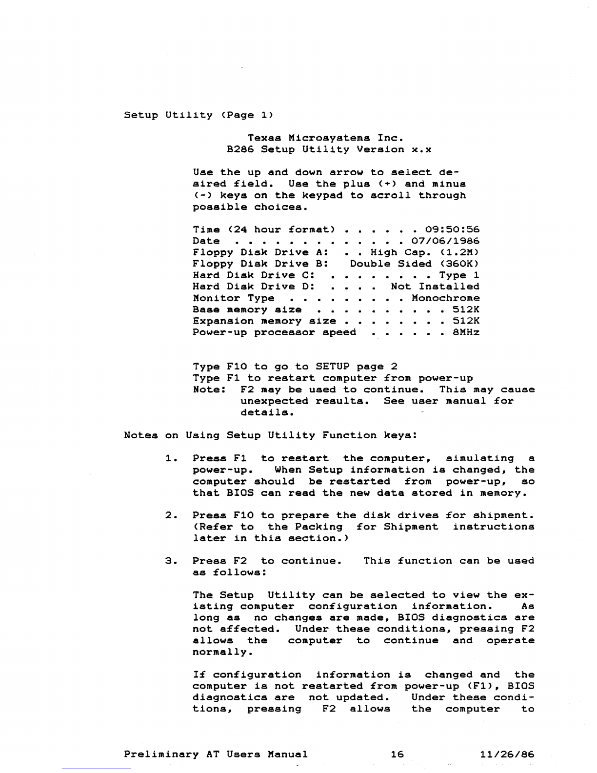
Setup
Utility
(Page
1)
Texas
Microsystems
Inc.
B286
Setup
Utility
Version
x.x
Use
the
up
and
down
arrow
to
select
de-
sired
£ield.
Use
the
plus
(+)
and
minus
(-)
keys
on
the
keypad
to
scroll
through
possible
choices.
Time
(24
hour
£ormat)
Date
• • • •
Floppy
Disk
Drive
A:
Floppy
Disk
Drive
B:
Hard
Disk
Drive
C:
Hard
Disk
Drive
D:
Monitor
Type
•
0<:3:50:56
•
07/06/1<:386
••
High
Csp.
(1.2M)
Double
Sided
(360K)
•
Type
1
Not
Installed
•
Monochrome
Base
memory
size
Expansion
memory
size
• •
Power-up
processor
speed
•
512K
•
512K
• 8MHz
Type
FlO
to
go
to
SETUP
page
2
Type
F1
to
restart
computer
£rom
power-up
Note:
F2
may
be
used
to
continue.
This
may
cause
unexpected
results.
See
user
manusl
£or
details.
Notes
on
Using
Setup
Utility
Function
keys:
1.
Press
F1
to
restart
the
computer,
simulating
a
power-up.
When
Setup
in£ormation
is
changed,
the
computer
should
be
restarted
£rom
power-up,
so
that
BIOS
can
read
the
new
data
stored
in
memory.
2.
Press
FlO
to
prepare
the
disk
drives
£or
shipment.
(Re£er
to
the
Packing
£or
Shipment
instructions
later
in
this
section.)
3.
Press
F2
to
continue.
as
£ollows:
This
£unction
can
be
used
The
Setup
Utility
can
be
selected
to
view
the
ex-
isting
computer
con£iguration
in£ormation.
As
long
as
no
changes
are
made,
BIOS
diagnostics
are
not
a££ected.
Under
these
conditions,
pressing
F2
allows
the
computer
to
continue
and
operate
normally.
I£
con£iguration
in£ormation
is
changed
and
the
computer
is
not
restarted
£rom
power-up
(F1),
BIOS
diagnostics
are
not
updated.
Under
these
condi-
tions,
pressing
F2
allows
the
computer
to
Preliminary
AT
Users
Manual
16
11/26/86
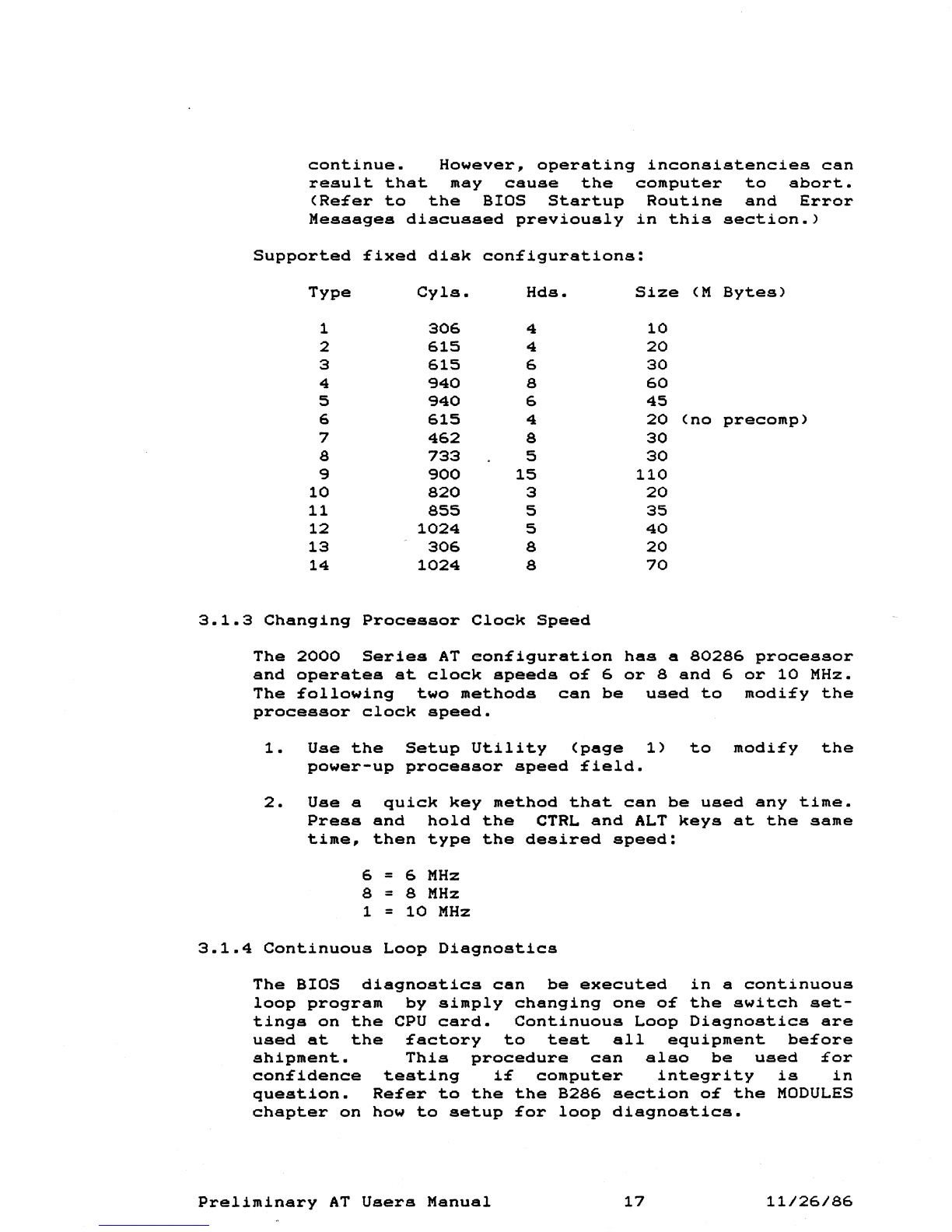
continue.
However~
operating
inconsistencies
can
result
that
may
cause
the
computer
to
abort.
(Re£er
to
the
BIOS
Startup
Routine
and
Error
Messages
discussed
previously
in
this
section.)
Supported
£ixed
disk
con£igurations:
Type
Cyls.
Hds.
Size
(M
Bytes)
1
306
4
10
2
615
4
20
3
615
6
30
4
940
8
60
5
940
6
45
6
615
4
20
(no
precomp)
7
462
8
30
8
733
5
30
9
900
15
110
10
820
3
20
11
855
5
35
12
1024
5
40
13
306
8
20
14
1024
8
70
3.1.3
Changing
Processor
Clock
Speed
The
2000
Series
AT
eon£iguration
has
a
80286
processor
and
operates
at
clock
speeds
o£
6
or
8
and
6
or
10
MHz.
The
£ollowing
two
methods
can
be
used
to
modi£y
the
processor
clock
speed.
1.
Use
the
Setup
Utility
(page
1)
to
modi£y
the
power-up
processor
speed
£ield.
2.
Use
a
quick
key
method
that
can
be
used
any
time.
Press
and
hold
the
CTRL
and
ALT
keys
at
the
same
time,
then
type
the
desired
speed:
6 = 6
MHz
8 = 8
MHz
1 =
10
MHz
3.1.4
Continuous
Loop
Diagnostics
The
BIOS
diagnostics
can
be
executed
in
a
continuous
loop
program
by
simply
changing
one
o£
the
switch
set-
tings
on
the
CPU
card.
Continuous
Loop
Diagnostics
are
used
at
the
£actory
to
test
all
equipment
be£ore
shipment.
This
procedure
can
also
be
used
£or
con£idence
testing
i£
computer
integrity
is
in
question.
Re£er
to
the
the
B286
section
o£
the
MODULES
chapter
on
how
to
setup
£or
loop
diagnostics.
Preliminary
AT
Users
Manual
17
11/26/86
This manual suits for next models
3
Table of contents
Popular Industrial PC manuals by other brands


Kontron Embedded Computers
Kontron Embedded Computers KISS 4U user manual

ADLINK Technology
ADLINK Technology DLAP-411-Orin user manual

Rockwell Automation
Rockwell Automation Allen-Bradley VersaView 6300B user manual

Connect Tech
Connect Tech Polaris ESG604 Series user guide

Siemens
Siemens SIMATIC IPC277G operating instructions

AXIOMTEK
AXIOMTEK PANEL1080-845 user manual