Touch Dynamic Orion User manual

Orion
User Manual
Revision v1.0 December

2
Copyright 2009 February
All Rights Reserved
Manual Version 1.0
Part Number:
The information contained in this document is subject to change without notice.
We make no warranty of any kind with regard to this material, including, but not limited to, the
implied warranties of merchantability and fitness for a particular purpose. We shall not be liable
for errors contained herein or for incidental or consequential damages in connection with the
furnishing, performance, or use of this material.
This document contains proprietary information that is protected by copyright. All rights are
reserved. No part of this document may be photocopied, reproduced or translated to another
language without the prior written consent of the manufacturer.
TRADEMARK
Intel®, Pentium® and MMX are registered trademarks of Intel® Corporation. Microsoft® and
Windows® are registered trademarks of Microsoft Corporation.
Other trademarks mentioned herein are the property of their respective owners.

3
Safety
IMPORTANT SAFETY INSTRUCTIONS
1. To disconnect the machine from the electrical power supply, turn off the power switch and
remove the power cord plug from the wall socket. The wall socket must be easily
accessible and in close proximity to the machine.
2. Read these instructions carefully. Save these instructions for future reference.
3. Follow all warnings and instructions marked on the product.
4. Do not use this product near water.
5. Do not place this product on an unstable cart, stand, or table. The product may fall,
causing serious damage to the product.
6. Slots and openings in the cabinet and the back or bottom are provided for ventilation to
ensure reliable operation of the product and to protect it from overheating. These openings
must not be blocked or covered. The openings should never be blocked by placing the
product on a bed, sofa, rug, or other similar surface. This product should never be placed
near or over a radiator or heat register or in a built-in installation unless proper ventilation
is provided.
7. This product should be operated from the type of power indicated on the marking label. If
you are not sure of the type of power available, consult your dealer or local power
company.
8. Do not allow anything to rest on the power cord. Do not locate this product where persons
will walk on the cord.
9. Never push objects of any kind into this product through cabinet slots as they may touch
dangerous voltage points or short out parts that could result in a fire or electric shock.
Never spill liquid of any kind on the product.
CE MARK
This device complies with the requirements of the EEC directive 2004/108/EC
with regard to “Electromagnetic compatibility” and 2006/95/EC “Low Voltage
Directive”.
FCC This device complies with part 15 of the FCC rules. Operation is subject to the following two
conditions:
(1) This device may not cause harmful interference.
(2) This device must accept any interference received, including interference that may cause
undesired operation.

4
CAUTION ON LITHIUM BATTERIES
There is a danger of explosion if the battery is replaced incorrectly. Replace only with the same
or equivalent type recommended by the manufacturer. Discard used batteries according to the
manufacturer’s instructions.
LEGISLATION AND WEEE SYMBOL
2002/96/EC Waste Electrical and Electronic Equipment Directive on the treatment, collection,
recycling and disposal of electric and electronic devices and their components.
The crossed dustbin symbol on the device means that it should not be disposed of with other
household wastes at the end of its working life. Instead, the device should be taken to the waste
collection centers for activation of the treatment, collection, recycling and disposal procedure.
To prevent possible harm to the environment or human health from uncontrolled waste disposal,
please separate this from other types of wastes and recycle it responsibly to promote the
sustainable reuse of material resources.
Household users should contact either the retailer where they purchased this product, or their
local government office, for details of where and how they can take this item for environmentally
safe recycling.
Business users should contact their supplier and check the terms and conditions of the
purchase contract.
This product should not be mixed with other commercial wastes for disposal.

5
Revision History
Changes to the original user manual are listed below:
Version Date Description
1.0 2009 December Initial release

6
Table of Content
1. Packing List..................................................................................................................7
2. System View.................................................................................................................8
2.1. Front View............................................................................................................8
2.2. Rear View............................................................................................................9
3. Peripherals Installation ...............................................................................................10
3.1. B89 Cash Drawer Installation ............................................................................10
3.2. B99 Cash Drawer Installation ............................................................................12
4. System Disassembly ..................................................................................................14
4.1. Removing the Front Cover.................................................................................14
4.2. Removing the Top Cover ...................................................................................15
4.3. Replacing the HDD............................................................................................15
4.4. Replacing the DVD-ROM...................................................................................17
4.5. Replacing the Power Supply..............................................................................18
4.6. Replacing the I/O & PCI Extension Module.......................................................19
4.7. Replacing the Memory.......................................................................................20
4.8. Replacing the Motherboard ...............................................................................20
5. Specification ...............................................................................................................22
6. Jumper Settings..........................................................................................................24
6.1. B89 Jumper Settings .........................................................................................24
6.2. B99 Jumper Settings .........................................................................................29
Appendix A: PCI Card Dimension......................................................................................36
Appendix B: Drivers Installation.........................................................................................37

7
1. Packing List
Take the system unit out of the carton. Remove the unit from the carton by holding it by the
foam inserts. The following contents should be found in the carton:
a. Driver CD
b. Power Cable
Note: The power cord type various according to different country and region.
8
2. System View
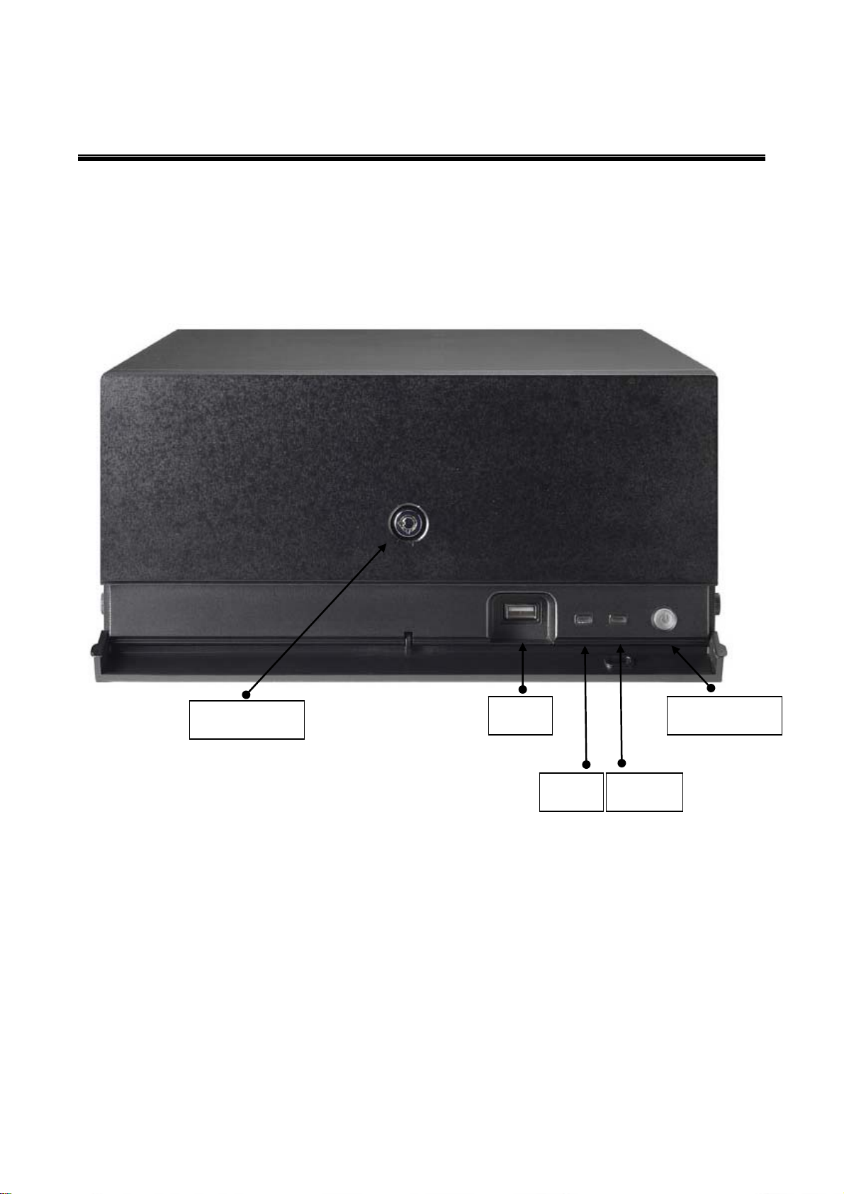
2.1. Front View
USB
HDD Power
Power Button
Key Lock

9
2.2. Rear View
Note: The maximum current that can be drawn from each COM port is 500 mA.
DC output 24V Pin Assignment
AC Power
Power
USB
24V
Power
USB
12V
Power
USB
5V USB
COM2 & 4
Line Out
VGA
COM 3 & 5
C
ash
Drawer P/S 2
Keyboard
DC Output 24V
COM 6
LPT
COM1 DC Output 12V LAN
USB
10
3. Peripherals Installation
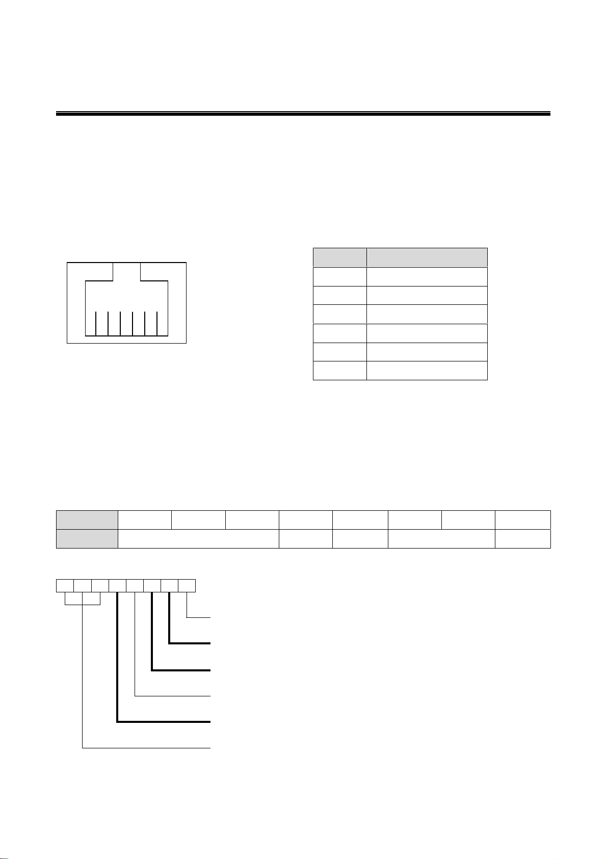
3.1. B89 Cash Drawer Installation
You can install a cash drawer through the cash drawer port. Please verify the pin
assignment before installation
Cash Drawer Pin Assignment
Cash Drawer Controller Register
The Cash Drawer Controller use one I/O addresses to control the Cash Drawer.
Register Location: 4B8h
Attribute: Read / Write
Size: 8bit
BIT BIT7 BIT6 BIT5 BIT4 BIT3 BIT2 BIT1 BIT0
Attribute Reserved Read Reserved Write Reserved
7 6 5 4 3 2 1 0
X X X X X
Reserved
Cash Drawer “DOUT bit1” pin output control
Cash Drawer “DOUT bit0” pin output control
Reserved
Cash Drawer “DIN bit0” pin input status
Reserved
6 1
Pin Signal
1 GND
2 DOUT bit0
3 DIN bit0
4 12V / 24V
5 DOUT bit1
6 GND

11
Bit 7: Reserved.
Bit 6: Reserved.
Bit 5: Reserved.
Bit 4: Cash Drawer “DIN bit0” pin input status.
= 1: the Cash Drawer closed or no Cash Drawer.
= 0: the Cash Drawer opened.
Bit 3: Reserved.
Bit 2: Cash Drawer “DOUT bit0” pin output control.
= 1: Opening the Cash Drawer
= 0: Allow closing the Cash Drawer
Bit 1: Cash Drawer “DOUT bit1” pin output control.
= 1: Opening the Cash Drawer
= 0: Allow closing the Cash Drawer
Bit 0: Reserved
Note: Please follow the Cash Drawer control signal design to control the Cash Drawer
Cash Drawer Control Command Example
Use Debug.EXE program under DOS or Windows98
Command Cash Drawer
O 4B8 04 Opening
O 4B8 00 Allow to closing
Set the I/O address 4B8h bit2 =1 for opening the Cash Drawer by “DOUT bit0” pin
control.
Set the I/O address 4B8h bit2 = 0 to allow closing Cash Drawer.
Command Cash Drawer
I 4B8 Check status
The I/O address 4B8h bit4 =1 means the Cash Drawer is closed or no Cash Drawer.
The I/O address 4B8h bit4 =0 means the Cash Drawer is open.
12
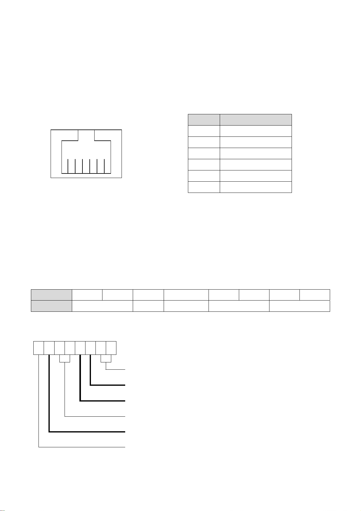
3.2. B99 Cash Drawer Installation
You can install a cash drawer through the cash drawer port. Please verify the pin
assignment before installation.
Cash Drawer Pin Assignment
Cash Drawer Controller Register
The Cash Drawer Controller use one I/O addresses to control the Cash Drawer.
Register Location: 48Ch
Attribute: Read / Write
Size: 8bit
BIT BIT7 BIT6 BIT5 BIT4 BIT3 BIT2 BIT1 BIT0
Attribute Reserved Read Reserved Write Reserved
7 6 5 4 3 2 1 0
X X X X X
Reserved
Cash Drawer “DOUT bit0” pin output control
Cash Drawer “DOUT bit1” pin output control
Reserved
Cash Drawer “DIN bit0” pin output control
Reserved
6 1
Pin Signal
1 GND
2 DOUT bit0
3 DIN bit0
4 12V / 24V
5 DOUT bit1
6 GND

13
Bit 7: Reserved
Bit 6: Cash Drawer “DIN bit0” pin input status.
= 1: the Cash Drawer closed or no Cash Drawer
= 0: the Cash Drawer opened
Bit 5: Reserved
Bit 4: Reserved
Bit 3: Cash Drawer “DOUT bit1” pin output control.
= 1: Opening the Cash Drawer
= 0: Allow close the Cash Drawer
Bit 2: Cash Drawer “DOUT bit0” pin output control.
= 1: Opening the Cash Drawer
= 0: Allow close the Cash Drawer
Bit 1: Reserved
Bit 0: Reserved
Note: Please follow the Cash Drawer control signal design to control the Cash Drawer.
Cash Drawer Control Command Example
Use Debug.EXE program under DOS or Windows98
Command Cash Drawer
O 48C 04 Opening
O 48C 00 Allow to close
Set the I/O address 48Ch bit2 =1 for opening Cash Drawer by “DOUT bit0” pin control.
Set the I/O address 48Ch bit2 = 0 for allow close Cash Drawer.
Command Cash Drawer
I 48C Check status
The I/O address 48Ch bit6 =1 mean the Cash Drawer is opened or not exist.
The I/O address 48Ch bit6 =0 mean the Cash Drawer is closed.
14
4. System Disassembly
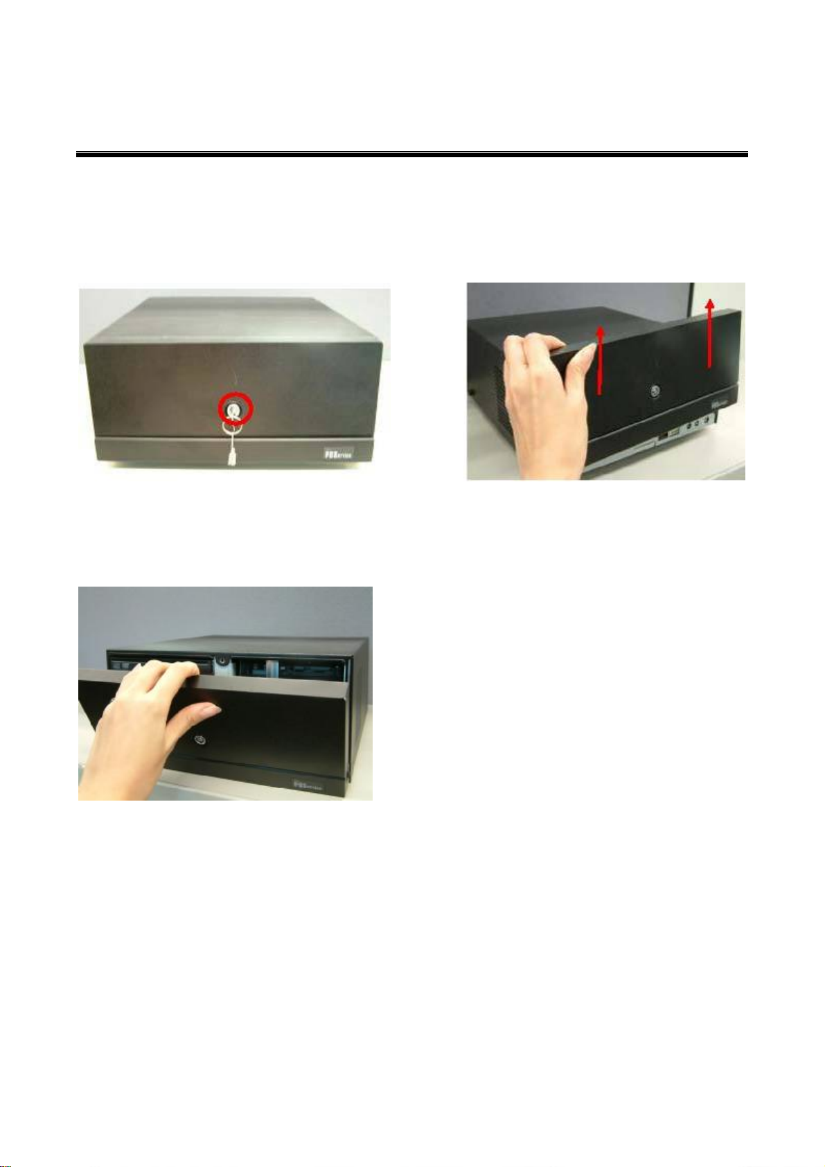
4.1. Removing the Front Cover
a.Use the key to unlock the front cover
Remove the front cover b.Lift the front cover up in the direction
as shown by the arrows
c.Remove the front cover

15
4.2. Removing the Top Cover
To remove the top cover, please follow the steps as described in chapter 5.1.
a.Remove the screw (1) b.Loosen the thumb screws (4) (two
from each side) to release the top
cover from the system.
4.3. Replacing the HDD
To replace the front cover, please follow the steps as described in chapter 5.1.
a.Loosen the thumb screw (1). b.Loosen the locking bar (1).

16
c.Disconnect the cables (4). d.Use your finger to pull the HDD holder
out.
e.Remove the HDD. f. Repeat the step d. and e. to remove
the other HDD.

17
4.4. Replacing the DVD-ROM
To replace the front cover, please follow the steps as described in chapter 5.1
a.Loosen the thumb screw (1) b.Pull the DVD-ROM holder out
c.Disconnect the cables (2) to remove the
DVD-ROM

18
4.5. Replacing the Power Supply
To replace the power supply, please follow the steps as described in chapter 5.1 and 5.2
d.Remove the screw (1) and slide the e.Disconnect the cables (3) to release the
power supply holder in the direction as
power supply holder from the system.
shown by the arrow.
f. Remove the screws (3) to separate the
power supply from the holder.

19
4.6. Replacing the I/O & PCI Extension Module
To replace the I/O and PCI extension module, please follow the steps as described in
chapter 5.1 and 5.2
a.Remove the extension module by gently
pulling it upwards taking care not to
damage the connector.
b.Disconnect the cables (3) and remove
the I/O module from the holder.
c.Disconnect the cables (2) and remove the
screws (2) to release the PCI riser card
from the holder.

20
4.7. Replacing the Memory
To replace the memory, please follow the steps as described in chapter 5.1, 5.2, 5.5(a)
a.Use your finger to push the DIMM slot
ejector clips into the down position. b.Remove the memory module from the
slot.
4.8. Replacing the Motherboard
To replace the motherboard, please follow the steps as described in chapter 5.1, 5.2, 5.5(a)
and 5.6(a)
a.Disconnect the cables (2), remove the
screws (2) and slide the HDD module in
the direction as shown by the arrows to
release the module from the
motherboard Chassis
b.Remove the screw (1) and disconnect
the cables (9) as shown in the picture.
Table of contents
Other Touch Dynamic Industrial PC manuals

Popular Industrial PC manuals by other brands

Advantech
Advantech IPPC-6152A user manual

IBASE Technology
IBASE Technology ASB200-918 Series user manual

Advantech-DLoG
Advantech-DLoG DLT-V4108 quick start guide

Siemens
Siemens SIMATIC IPC547E operating instructions

AXIOMTEK
AXIOMTEK IPC960A Series user manual

Avalue Technology
Avalue Technology ECM-TGU user manual


Siemens
Siemens SIMATIC HMI Start-up instructions

Lenze
Lenze L-force CPC 2800 Mounting instructions

Neousys Technology
Neousys Technology Nuvo-9501 user manual

IBASE Technology
IBASE Technology SI-58 Series user manual

Beckhoff
Beckhoff CP65 Series Installation and operating instructions

Kontron
Kontron KBox Series user guide