CROSSRC CZRFR4RTR User manual
Radiosysteminstructions
Caution
1
To preventseriouspersonalinjuryand/orpropertydamage,operateallremotely
controlledmodelsinaresponsiblemannerasoutlinedherein.
SafetyPrecautions
1.1Thisradio-controlled model isnotatoy,itisdesigned forpersons14 years ofage orolder.
1.2 Donotoperateyourvehicleonunsafeterrain;alwayspayattentiontoyoursurroundings.
1.3 Neveroperateyourvehicleonpublicroadways,aroundmovingpeople,animals,oroperatingmachinery.
1.4 Keepclearofpowerlinesandhigh-poweredradioequipmenttominimizeradiofrequencyinterference.
1.5 Sincethisvehiclecontainssmallcomponents,itmaybeachokinghazardforsmallchildren.Keepthe vehicle and
anysparepartsoutofreachofsmallchildren.
Inspectyourradio-controlledmodelbeforeoperation
2.1 Ensurethat all screwsareproperly tightened. Usethread-locktosecureany metalto metalcontacts- especially forcomponents designed
towithstand torque(servomounts, motormount, drive shaft grub screwsetc.).
2.2 Alwayscheckthebattery voltage forboth thetransmitterand vehiclepriortooperating yourvehicle.Keep the batteriesfresh in the
transmitterand alwaysbegin yourvehiclerunswith afully charged battery pack.
2.3 Alwayscheckthat themotorand servoareoperatingsmoothly and in therightdirection priorto operation.Ifbinding between
components isobserved,replaceparts as necessary toreducepossibility ofcomponentorservo damage.
2.4 Toturn on yourvehicle,alwayspoweron yourtransmitterfirst, then poweron yourreceiver.
Afteroperatingyourradio-controlledmodel
3.1 Toturn off thevehicle,alwayspoweroff yourreceiverpriorto powering off yourtransmitter.
3.2 Usecaution when handlingthevehicle-components, especially theESCand motorwhich will be hotafteroperation.
3.3 Neverusebattery packswhich aredented orotherwisedamaged. Ensurethat the wire insulation isintact and that connectors are
properly soldered. Lithiumbatteriescan become fire hazardsifmishandled.
ABCDE
F
G
H
I
J K L M
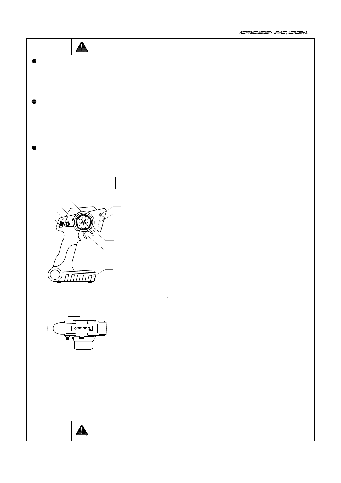
A.On/Off switch: Ensure that the throttle and steeringchannels
are attheirneutral positionpriortoturningonthe transmitter.
B.Steeringrates:Increases ordecreases the maximumsteering
servodeflection.
C. Throttle trim:Adjusts the neutral positionof the throttle output.
D:Steeringtrim:Adjusts the neutral positionof the steeringservo.
E:Bind button: Usedforbindingthe transmittertothe receiver.
F:Antenna: Aninternal2.4GHzantennaislocated atthis position.
G: Steeringwheel:Proportional controlforthe steeringservo.
H:Throttle trigger: Proportional controlforthe ESC and motoroutput.
I:Battery compartment: Accepts 4x AA”batteries.
J:PowerLED:Flashes whenbattery voltage is low.
K:Steeringreverse:Reverses the directionof travel forthe
steeringservo.
L: Throttle reverse:Reverses the directionof travel forthe
motor output.
M:Bind LED Flashes duringthe bindingprocess.
Caution Do not obstruct theantennacoverasit mayreducetheoperatingrangeof
theradiosystem.
TransmitterSpecifications
-Intendeduse:Surfacevehicles
-Numberofchannels:2
-Frequency:2.4GHzISMFrequencyrange
-Spread spectrummode:Frequencyhoppingspread-spectrum(FHSS)
-Modulationformat:FSK/GFSK
-Outputpower:<100mW
-Operatingcurrent<150mA
-Resolution:1024uS
-Proportional throttle and steeringcontrols
-Steeringservodualrates
-Throttle EPA
-Lowvoltagewarning
-Fail safe protection
-Certificates:CE/FCC

s+-
CH2
CH1
BIND
BT-R2
MADE IN CHINA
2
LED
Connections
CH2”:Throttlechannel
CH1”:Steeringservo
BIND”:Bindplugorexternalpowerinput
Receiverparameters:
-Intendeduse:Surfacevehicles
-Channels:2
-Frequency:2.4GHzISMFrequencyrange
-Spreadspectrummode:Frequencyhoppingspread-spectrum(FHSS)
-Modulationformat:FSK/GFSK
-Resolution:1024
-Sensitivity:-97dBm
-Inputvoltage:4.8-6.0V
-Certificates:CE/ FCC
Safety guide
-Do not cover theantennahousing onthetransmitter withyourhand orother materials
during operationasit may affect theeffectiverangeoftheradio system.
-Disconnect themotorfromtheESCwhenperforming thebind process.
-If using anindependent receiver battery, alwaysensure that thebattery pack is fully
chargedpriorto operation.
-Do not expose theradio system to direct contact withmoisture. Excessivehumidity may
decrease therangeoftheradio and irreversibly damagesensitive electronic components.
Transmitter/ReceiverBinding
●Insertthebindingcableinto theBINDportofthereceiver.
●TurnonthereceiverandtheLEDshouldflashquickly,indicatingthereceiveris
inbindingmode.
●Press and holdtheBINDbuttononthetransmitter,thenTurnonthetransmitter.
TheBINDLEDofthetransmittershouldflash,indicating thetransmitterisinbindingmode.
●After bindingis completed,theLEDoftransmitterand receiver shouldchangeto solidGREEN.
Otherwise, repeattheaboveoperationagain.
SettingtheFail-safefunction (F/S)
Intheunlikelyeventofradio-loss,thefail-safefunctionbuiltintothis radio system will giveapreset
outputvaluetothethrottlechanneluntilthereceiverreceivesfurther signals fromthetransmitter.
To setthefail-safe,
1.Turnonthetransmitter,thenthereceiver
2.InsertthebindplugintotheBINDport onthereceiver
3.After2seconds,thestatusLEDonthereceiverwillflashquickly,indicating that it is ready for
aFail-safe value.
4.Returnthethrottletriggertoitsneutral position
5.RemovethebindplugfromtheBINDport
6.Fail-safesettingcomplete
Radiosystembindprocess:
1.Disconnect themotorfromtheESC.
2.Insert thebind plug into the BIND”port ofthereceiver.
3.Turnonthereceiver. ThestatusLEDonthereceiver shouldflashrapidly-indicating that the
unit hasenteredthebind process.
4.Press and holdtheBIND buttononthetransmitter. While holding thebind button,power on
thetransmitterusing theON/OFF switch.TheBIND LEDonthetransmitterwill flash,indicating
thetransmitterhasenteredthebind process.
5.Thetransmittershouldnowpair automatically to thereceiver. Thetransmitterand receiver
LEDsshouldturnsolidgreenonce thebind process hasbeencompleted.
6.Removethebind plug thenpower off thereceiver and transmitter. Connect themotorto the
ESCpriorto powering thesystem onagain.
7.Shouldthebind process fail, repeat steps2-5.

UserManualofWater-ProofBrushedSpeedController(RTRVersion)
FEATURES】
1.Weather-proofand dust-proofdesign ensures increaseddurability
2.Compact sizewithbuilt-incapacitor
3.Automaticthrottle-rangecalibration
4.Multiple system protection: Lowvoltagecutoff forLiPoand NiMH batteries; Temperature
protection;Throttle signalloss protection.
5.Easily programmable using includedjumpers.
SPECIFICATIONS】
Model WP-1060-BRUSHED
Cont./Burst Current Forward:60A/360A Backward: 30A / 180A
Input
Motor
Limit
2S Lipo
5-6 cells NiMH
2-3SLipo,5-9CellsNiMH
3S Lipo
7-9 cells NiMH
540or550sizemotor ≥8TorRPM<45000@7.2V
540or550sizemotor ≥13TorRPM<30000@7.2V
Resistance 3A/6V(SwitchmodeBEC)
Built-in BEC
Dimension & Weight
Fwd: 0.0008 Ohm, Bwd: 0.0016 Ohm
36*30*18,40g
SETUP INSTRUCTIONS】
1.Connectthe ESC, motor, receiver, battery and servoaccordingtothe diagramabove. Paycareful attention
tothe polarities of all plugs and cables.Ifthe polarity of the battery is reversed, the ESC can become
permanently damaged.The polarity of the motorcables maybe switched, this will reverse the direction
in whichthe motorrotates.
2.Transmittersettings:
-Please setthe throttle rates, ATLand EPA to100%togive the throttle channel maximumtravel range,
where applicable.
-Set the throttle trimtoneutral
-Reverse the throttle channel onFutaba radios;forall otherradios, setthe throttle channel reverse to
NOR”or Normal.
Set the fail-safe function.Refertothe instructions listed in this manual.
3
Black
Red
White Servo
LED
Black
Red
White Servo
Switch
Brushed
Motor
Battery
(Notincluded)
s+ -
CH2
CH1
BIND
BT-R2
MADE IN CHIAN
ONOFF
To "CH2"channel
Motor-
Motor+
(Blue)
(Yellow)
Battery-(Black)
Battery+(Red)
To "CH1"channel
ESC Usermanual (RTR Version)
Theelectronic speedcontroller (ESC) that isincludedwiththeready-to-run (RTR) set isahigh
quality, waterresistant electronic component that interprets thethrottle signalfromthereceiver
and powers themotoraccordingly.Asthepower system inthis vehicle canbedamagedif used
incorrectly, it isvitalfortheuser to readand study thefollowing sectionvery carefully. In that we
have no control over the correct use, installation,application, or maintenance of our
products, no liability shall be assumed nor accepted for any damages,losses or costs
resulting from the use of the product

3.ThrottleRangeSetting(ThrottleRange Calibration)
In order to make the ESC match the throttle range of different transmitters, the calibrationof
the ESC is necessary.To calibrate the ESC, please turn on the transmitter, keep throttle stick
at its neutral position, wait for 3 seconds to let the ESC execute self-test and automatic
throttle calibration. When the ESC is ready to run, a long beep sound is emitted from the motor.
Note: Please calibrate the throttle range again when using a new transmitter or changing the
settings of the neutral position of throttle channel, D/R, ATV, ATL or EPA parameters,
otherwise the ESC may not work properly
AUDIOANDVISUALCUES】
Audio(Beeps) Visual (LED)
1short Beep”:NiMH/NiCdbatterydetected
2short Beeps”:2SLiPodetected
3short Beeps”:3SLiPodetected
1long Beep”:Self-testandthrottlecalibration
completed,ESCisnowfunctional
LEDOff:Throttleisinneutralrange
LEDBlink:Partialthrottle,brakeorreversedetected.
LEDSolid:Fullthrottle
THROTTLETRIGGER POSITION】
PROTECTIONFUNCTIONALITY】
ESCCONFIGURATION】
The ESC is programmedusing jumpers. Itis recommendedthattweezersare usedtoremove or insertthe jumpers.
1. Low voltage cut-off (LVC)protection:If the voltage of the battery packis lowerthanthe presetthresholds forthe detected
battery type and remains lowerformorethan2seconds,the ESCwill enterprotection mode;the ESC will provide no powerto
themotorregardlessofthrottleposition,butstillprovidepowertothereceivertomaintainsteeringfunctionality.The red LED
willblink toindicatethattheESChasenteredintoprotectionmode.
LVC protection for WP-1060-BRUSHED, (F/B/R or F/B mode).
2S Lipo 3S Lipo 5-9 cells NiMH
Output reduces 50% at 6.5V
Output cuts off at 6.0V,
cannotberecovered
Outputreduces50%at9.75V
Output cuts off at 9.0V,
cannotberecovered
Output reduces 50% at 4.5V
Output cuts off at 4.0V,
cannotberecovered
4
ONOFF
MODE
BATT Lipo NiMH
F/B/RF/BF/R
F/B/R:Forward,brake and reverse
F/B:Forward with brake
F/R:Forward and reverse(Crawler mode)
WP-1060-BRUSHED
Neutralposition Full forward Full reverse or brake,if applicable.

2. Over-heatprotection:WhentheESCdetectsaninternaltemperatureinexcessof100degreesCelsiusor 212
degreesFahrenheitfor more than5seconds, theESC will firstreduce thencut-off power tothe motor.
The redLEDwill blinktoindicate thatithas enteredprotection mode. Asthe ESC cools toatemperature
lower than80 degreesCelsius or 178 degreesFahrenheit, the ESC will resume normalfunctionality.
3. Throttle signalloss protection: The ESC will terminate motor outputif the throttle signalis lostin excess of
0.1seconds. Thisfunction is notareplacementforthe fail-safe functionalityof the radio system.
The radio fail-safe function should always be usedin conjunction withthe built-in protection of the ESC.
TROUBLESHOOTING】
Symptom Possible causes Possible solutions
The ESC switchis ON butthe motor
doesnotfunction,no sound is emitted,
and the LEDis off
The ESC isnotreceivingadequate voltage.
Connection betweenthebattery and ESC
islost
Switchisdamaged.
Checkbattery voltage;checkwires and
connectorsforabad connection.
Replace theswitch.
The ESC LEDblinksbutthe motordoes
notfunction. Throttlesignalisabnormal. Checkthatthe throttle cable is pluggedinto
thethrottleport
Automatic throttlerangecalibration
has failed. Setthethrottletrimtoitsneutral position
and ensure thatthe physicalthrottle is atits
neutralposition.
The motorturns inadirection opposite to
thethrottleinput. Motorpolarityis reversed. Swap thetwowiresthatconnect the ESC
tothemotor.
Thetruckis unableto reverse. Thejumperposition is incorrect. Checkthejumperand insert itinto the
correct position.
Theneutral pointofthethrottle channel
has changed. Setthethrottletrim to0 then perform an
automaticcalibration.
Thetruckcan only movein reverse Thereversefunctionofthethrottle channel
is incorrect. Reversethethrottlechannelfrom NORto
REVorfrom REVto NOR.
Themotordoesnotfunction despite
correct LEDsignals Theconnectionbetweenthe ESC and
motoris broken. Checktheconnectionbetween the
ESC and motor.
Motoris damaged. Replacemotor.
Abrupt motorstopduringnormal
operations Thethrottlesignal is lost. Checktheradiosystem forpossible signal
loss; checkthereceiver/ESC connection.
Lowvoltagecutoff protectionor Over-heat
protectionhas beenactivated (CheckLED) Replacebattery packorwaituntil system
cools toasafetemperature.
Themotordoesnotreach full operational
speedand theLEDdoesnot staysolid
atfull throttle
Transmittersettingis incorrect or ESC
requiresrecalibration Confirm thattheD/R, EPA,ATLsettingsare
at100%whereapplicable.Set throttletrim
toitsneutral position.
Motorcogswhenacceleratingquickly Thebattery has inadequate discharge
capability. Changetoahigherdischarge-rate battery.
MotorRPM is too highor the gear ratio
is too aggressive. ChangetoalowerRPM motor or alower
gear ratio.
Drivesystem damage. Checkdrivesystem for damage.
5

M3x4
11401
M3x8
11106
1
THREAD
LOCK
11401
41293
11106
32704
17009
200203
95028
11130
11130
M2x20
2Stop:
TestthegearmeshbyconnectingtheESCtothemotor/gearbox
assembly.Ifthegearboxisnotoperatingsmoothlyoriscreatingexcess
noise,checkthegearmeshpriortoproceedingtothe next step.
3
11116
M2.5x12
11116 200201
200202
5x 11x4
15006
5x8x0.3
72007
41292
72007
15006
72007
15006
6
THREAD
LOCK
THREAD
LOCK
Electronics
speedcontrol
Black
Red
White
ON/OFF
Switch
Battery
(Notincluded)
s+ -
TH
ST
BIND
BT-R2
MADE IN CHIAN
ONOFF

4
11206
M3x8
11206
11108
11106
M3x8
11106
11106
11206
11108
204206
71116
71117
204207
204404
204403
73044
204303
204405
7
11108
M3x12

5
8
21217
21217
87078
Yellow
Yellow
6
201504
11106
M3x8
11106
11106
11106 11106
200910

7
M3x8
11303
11106
M3x8
11106
11106
11303
204301
204302
9
205008

SHOCK
OIL
17007
17008
Ø6.5xØ2.5xØ2
Ø7xØ5xØ1
13004
2.0x 5.5x0.4
13004
200501
41197
41418
42312
42313
17007
41196
17007
200103
41198
17008
41195
41336
41368
200401
41336
10
SHOCK
OIL
8
x4
x4
SHOCK
OIL
28.5mm

11
Adjustthebacklash
withtheShims.
15004
15004
72008
72008 32102 13003
32101
41246
15003
15004
10x 15x4
13003
72007
72008
13002 15003
15003
72007 13002
202002
Adjustthe
backlash
withtheShims.
9
x2
10
Ø5xØ8x0.3
Ø5xØ10x4
Ø3.8xØ9.2x0.6
Ø2.5xØ6.2x0.4
Ø10.2xØ15x0.2
11133 202001
201901
11120
15003
15003
41248
41250
12206
13002
Ø3.8xØ9.2x0.6
13002
13002
11
M2
12206
11120
11133 M2x12
15003
Ø5xØ10x4
M2.5x20

11207M3x10
15003
15004
10x 15x4 15003
41205
15003
202003
41205
41205 15004
11207
11207
11111
73042
11207
41205
202004
15004
11207
41208
41208
12
13 15003
15003
72007 13002
Adjustthe
backlash
withtheShims.
15003
72007
13002
202102
11120 M2.5x20
11133
11133
11120
15003
15003
41249
15003
41247
202101
201901
14 12206
12206
12206
11133 M2x12
M2
12206
GREASE
Ø5xØ10x4 x2
Ø.8xØ9.2x0.6 X1
Ø5xØ8x0.3x1
M3x18
11111
12
12

15
13
M3x16
11407
11407
41143
11407 41336
x2 200103
41336
200103
11407
11407
41125
x2
M3
12203
12203
41336
16
95mm
80.5mm
41336
200102
41336
200103
M3x18
11111 11111
95mm
80.5mm
80.5mm
95mm
11111
11114
11114
11114 M3x25
M3x18
11111
11111
73042

201602
M3x8
11303 11303 71025
11206
M3x8
11206
11409
11409
M4x11
95033
18
THREAD
LOCK
17
14
12203
12203
M3
12203
204208
204208
11114 M3x25
11114
11114
11117 M3x30
11117
11117

11407 41601 11407
41336
41336
200103
200103
11407 11407
41600
41336 41336
200101 200101
M3x16
11407
41336
11107
3x 7x0.5
14102
14102
14102
11107
M3
12203
12203
11106 27407
27407
11114
11111
11109
SERVO
M3x10
11107
M3x8
11106
M3x14
11109
100mm
51.5mm
15
19
51.5mm
100mm
12203
M3x18
11111
11114 M3x25
12203
Turnonthe Transmitter
then Receiver and set
the Steering ServoTrim
at the neutralposition
20

16
M3x16
11407
11407
41600
11407 41336
x2 200103
41336
41336
200103
11407
11407
41612
x2
M3
12203
12203
200102
41336
11409
M4x11
M3
12203
41164
21
100mm
86.5mm
THREAD
LOCK
41336
200103
100mm
86.5mm
86.5mm
100mm
11114 M3x25
M3x18
11111
11114
11114
11111
THREAD
LOCK
11212 M3x20
M3x20
11112
12203
12203
12203
12203
11409
95033
11112
11112
11212
11212
41164
41164
22
71160
71160

17
23
11303
41613
52.5mm
M3x8
11303
M3x20
11112
11114 M3x25
11409
M4x11
THREAD
LOCK
41164 11112
11112
41164
41164
11114
11114
11409
41613
THREAD
LOCK

18
41613
52.5mm
11114 M3x25
11409
M4x11
THREAD
LOCK
11114
11114
11109
11109
41613
24
11409
M3x14
11109
Left Right
THREAD
LOCK

19
M3x12
11108
11108
201601
M4x4
11405
11409
M4x11
11405
11409
95034
THREAD
LOCK
25
26
11106
M3x8
11106
11106
THREAD
LOCK
THREAD
LOCK

27
20
11106
M3x8
11106
11106
M3x8
11303
11303
11303
11106
11106
M3x14
11109
11109
42310
42310
204401
204402
202410
202410
202409
94015
94015
94015
91004
91004
206308(Ø11xØ5x5)
206308
(Ø11xØ5x5)
Table of contents
Other CROSSRC Motorized Toy Car manuals

CROSSRC
CROSSRC EMO XT4 User manual

CROSSRC
CROSSRC MC6A-1 User manual

CROSSRC
CROSSRC Demon SG4 User manual

CROSSRC
CROSSRC XX10 User manual

CROSSRC
CROSSRC MC4A User manual

CROSSRC
CROSSRC CROSS DC8 User manual

CROSSRC
CROSSRC MC6A User manual

CROSSRC
CROSSRC BT8 User manual

CROSSRC
CROSSRC KR4 C Flagship 4x4 KIT User manual

CROSSRC
CROSSRC Demon SR4C User manual
 User manual")


Popular Motorized Toy Car manuals by other brands


Axial
Axial Yeti R/C instruction manual

Kyosho
Kyosho GP TR-15 MONSTER TOURING 4WD instruction manual

Fisher-Price
Fisher-Price POWER WHEELS Barbie Jammin' Jeep WRANGLER Owner's manual with assembly instructions

HPI Racing
HPI Racing Blitz instruction manual

Carrera RC
Carrera RC 370200989 manual

marklin
marklin VW KAFER Einsatzfahrzeug user manual


