CROWN INDUSTRIAL Aut-o-doR 1265 User manual
Richards-\yilcox
GENERAL
OPERATOR
WIRING
AND
CONTROL
INFORMATION
~
1265
and
1266
SLIDE
DOOR
OPERATORS
Copvright © Richards-Wilcox
Mfg.
Co.
1983
CROWN INDUSTRIAL OPERATORS
• formerly Richards-Wilcox
[I
G 213 Michelle
Court
South
San
Francisco,
CA 94080
(650) 952·5150
Fax: (650) 873·1495
.:-:;/J:JU
G-997-R1
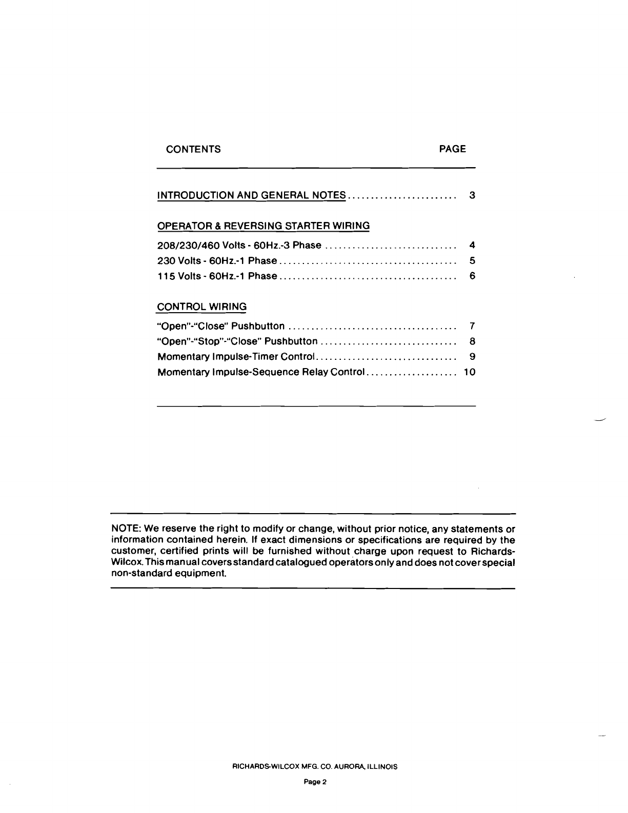
CONTENTS PAGE
INTRODUCTION AND GENERAL
NOTES........................
3
OPERATOR & REVERSING STARTERWIRING
208/230/460
Volts -60Hz.-3
Phase.
.... . . .. . ......... . .. . .. .... 4
230
Volts - 60Hz.-1
Phase.......................................
5
115
Volts - 60Hz.-1
Phase.......................................
6
CONTROL WIRING
"Open"-"Close"
Pushbutton.....................................
7
"Open"-"Stop"-UClose"
Pushbutton.
..... . . .... ....... .. . ........ 8
Momentary Impulse-Timer
Control...............................
9
Momentary Impulse-Sequence Relay
Control.
..... .... . .......
..
10
NOTE: We reserve
the
right to modify or change, without prior notice, any statements or
information contained herein. If exact dimensions or specifications are required by
the
customer, certified prints will
be
furnished without charge upon request to Richards-
Wilcox. This manualcoversstandardcatalogued operatorsonlyand does not
cover
special
non-standard equipment.
RICHARDS-WILCOX MFG. CO. AURORA,
ILLINOIS
Page 2
INTRODUCTION
The Richards-Wilcox No.
1265
and
1266
Slide Door Electric Operators are supplied
factory prepared for sitewiring. The purposeof thisbookletis to provide wiring diagrams
and instructionsfor
the
most popularof the controlsystems. The booklet isto be used in
connection with
the
installation Manual (G-996) supplied with each operator.
GENERAL NOTES
Wiring diagrams have been prepared to illustrate conditions with
the
door
in
the
fully
closed position.On
the
"Operatorand Reversing StarterWiring" pages 4 through 6 solid
lines have been used to denote factory wiring and dotted lines site wiring. On the
diagramsof "Control Wiring" pages 7 through 10, heavy
weight
lines have been used to
showsitewiring and lighter
weight
lines to
denote
factorywiring. On
the
"controlwiring"
diagrams,controlcircuittransformershave been shown. Controlcircuittransformersare
not provided with operators intended for use on
115
volt
power
supplies.where control
circuit powerconnections are to be made directlyacross the line. See general installa-
tion instruction manual (G-996) for establishing proper direction of
door
travel.
WARNING
Theoperatoristested at
the
factoryfor aspecified voltageand ismarkedas such.
Check
to insure that
your
power source is the same as shown on the packing list from
the
packing list envelope.
WARNING
BE SURE ALL POWER IS
ALWAYS
OFF WHILE
WIRING
OR SERVICING OPERA·
TOR. UPONAPPLYING POWER, SOME ELECTRICALOPERATORCONTROLCIR·
CUlTSCAN CAUSE IMMEDIATE OPERATION. INSURE
THAT
THE
PATH OF
THE
DOOR IS FREE FROM OBSTRUCTIONS AND PERSONNEL BEFORE
TURNING
POWER
ON.
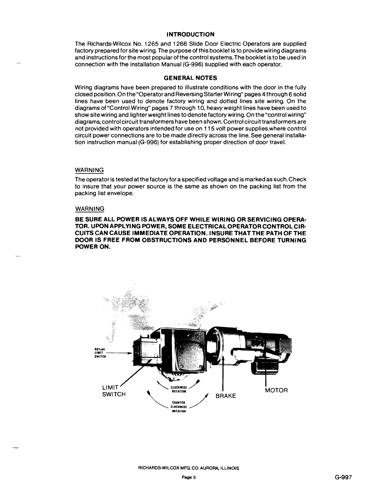
101,..,
LIMIT
------i.
SWITCN
G
LIMIT
"'-
CLOCKWISE
/
ROTAn
ON
MOTOR
SWITCH BRAKE
COUNHR
~
CLOCKWISE
/
ROTATION
RICHARDS-WILCOX MFG. co.AURORA,
ILLINOIS
Page 3 G-997

208/230-460
VOLTS THREE PHASE
Cll....
D.L.
OJ...
T2. T3
BRAKE & MOTOR CONNECTIONS
1--20-8-/2-30-V-O'Tril~60V~
I
rr=='NI
I
~ll
I~A~~I=~Il
~MOT~
MOTOR
___
TRANSFORMER
CoNNECTloNS
__
I
Z208/230~~;~OLTlINE
/I
IH'~
~H<fIH,lZ
H~HZ
~f
I~I~I
I
IC'O---
....
•
....
·---OU
[x/a
....
~.:::~u
I
OPERATORAND REVERSING STARTERWIRING
FOR
208/230/460
VOLTS - 60 HERTZ - 3 PHASE
POWER SUPPLIES WIRING
CODE
Solid
Lines
-
Factory
Wiring
Dotted
Lines
-
Site
Wiring
RICHARDS-WILCOX MFG.CO. AURORA,
ILLINOIS
Page
4
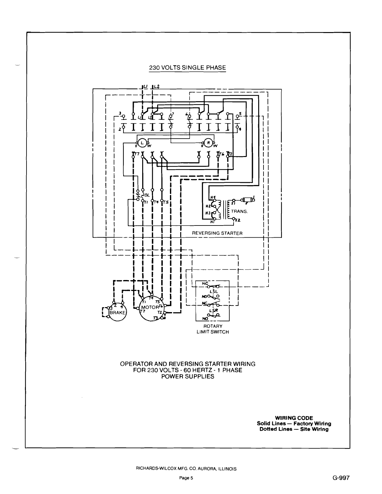
230
VOLTS SINGLE PHASE
.--
-I~
~1:::l4'------------
,----f-~-,
j-----------l
1
f~
Oo=f-
......
I I
~IIE:?
r- - - - - - J
r------
I I
I I
'f
sl I
I I I
I I I
I
r~
il
TTTl
I I
I
~~--
I I I I : I
I
I
I
I
I
I
I
I
,I
IIIIII
I
I
L--t-~-L"",~---+-,
I :
----rT-t-iTTT-----l II
I I I I I I
rl------t---
J I
I I I I I
III
I t
r--~-,'
III II
I~C--fTL
I
I +
II
I I I
-~
...J
I
r-
1 I I I
L~L
I
II
,.
1IIINO~,1
,.Jri
';OTO;:"
I
~1
~tJ
t~
7
T1.....J
NO~
ROTARY
LIMIT
SWITCH
OPERATOR AND REVERSING STARTER WIRING
FOR
230
VOLTS - 60 HERTZ - 1 PHASE
POWER SUPPLIES
WIRING CODE
Solid
Lines
-
Factory
Wiring
Dotted
Lines
-
Site
Wiring
RICHARDS-WILCOX MFG. CO. AURORA,
ILLINOIS
Page 5 G-997
This manual suits for next models
1
Table of contents
Popular Door Opening System manuals by other brands


Besam
Besam Swingmaster MP Installation, adjustment and maintenance instructions

Assa Abloy
Assa Abloy SARGENT 1431 Series instructions

GAL
GAL MOVFR Quick setup

Häfele
Häfele Finetta T 70 VF manual

AGS
AGS D-PL Instructions for fitting, operating and maintenance

Stanley
Stanley MA900ñ Installation and owner's manual

WITTUR
WITTUR Hydra Plus UD300 Instruction handbook

Alutech
Alutech TR-3019-230E-ICU Assembly and operation manual

Pamex
Pamex KT-INP35 Installation instruction

MPC
MPC ATD ACTUATOR 50 ATD-313186 Operating and OPERATING AND INSTALLATION Manual

Chamberlain
Chamberlain T user guide

Dorma
Dorma MUTO COMFORT M DORMOTION 50 Mounting instruction