manuals.online logo
Brands
  1. Home
  2. •
  3. Brands
  4. •
  5. WITTUR
  6. •
  7. Door Opening System
  8. •
  9. WITTUR Hydra Plus UD300 manual 

WITTUR Hydra Plus UD300 manual 

No part of this publication may be reproduced or translated,
even in part, without prior written permission from WITTUR.
© Copyright WITTUR 2013
Subject to change without notice!
URL: http://www.wittur.com
e-mail: info@wittur.com
Code
Version
GM.2.002668.EN
B
Code
Version
Date
3201.32.0397
B
04.02.2013
INSTRUCTION HANDBOOK
Hydra Plus UD300
Subject to change without notice!
Code
Version
GM.2.002668.EN
B
Code
Version
Date
3201.32.0397
B
04.02.2013
HYDRA PLUS UD300 CAR DOOR
BB
UUpp--ddaatteeddddooccuummeenntt''ssLLaayy--oouuttaannddtthheeffoolllloowwiinnggppaaggeess::88;;1144;;1199;;2255..AAddddeeddppaaggeess::1133;;2288;;2299;;3300;;3311;;3322;;3333;;
3344;;3355..
0044//0022//1133
AA
GGeenneerraalluupp--ddaattiinngg
0088//1111//1122
MMOODD..DDEESSIIGGNNAATTIIOONNDDAATTEE
Subject to change without notice!
EN
HYDRA PLUS UD300 CAR DOOR Code
Version
Code
Version
Date
Page
GM.2.002668.EN
B
3201.32.0397
B
04.02.2013
1.37
INDEX
11..GGeenneerraallddeessccrriippttiioonn.............................................................................
...............................................................................................................33
1.1 Operator fixing on car roof . . . . . . . . . . . . . . . . . . . . . . . . . . . . . . . . . . . . . . . . . . . . . . . . . . . . . . . . . . . . . . . . . . . . . . . . . . . . . . . . . . . 4
22..FFiittttiinnggaannddaaddjjuussttiinnggbbrraacckkeettss....................................................
....................................................................................................................88
33..LLaannddiinnggddoooorraalliiggnnmmeennttwwiitthhccaarrddoooorr...........................................
.............................................................................................................88
44..AAsssseemmbbllyyooffppaanneellffiixxiinnggbboollttss........................................................
................................................................................................................99
55..CClleeaarraanncceerreeccoovveerriinnggoofftthheeppaanneellaasssseemmbblliinnggbboollttss.................................
...............................................................................................1111
66.
.BBoottttoommsslliiddiinnggsshhooeessaasssseemmbbllyy,,mmaaiinntteennaanncceeaannddrreeppllaacceemmeenntt.........................................
...................................................................1122
77..FFiittttiinnggccaarrssiillllbbrraacckkeettss..
....................................................................................................................................................................................1133
7.1 Assembly of sill and toe guard . . . . . . . . . . . . . . . . . . . . . . . . . . . . . . . . . . . . . . . . . . . . . . . . . . . . . . . . . . . . . . . . . . . . . . . . . . . . . . . . 14
88..PPllaacciinnggtthhee
mmeecchhaanniissmmssoonntthheetthhrreesshhoollddss................................................................................................................................................1155
99..FFiixxiinnggoofftthheeccoouupplleerr.
.......................................................................................................................................................................................1166
1100..CCaarrddoooorrl
loocckk....................................................................................................................................................................................................1177
10.1 Aspects that must be checked during installation and maintenance . . . . . . . . . . . . . . . . . . . . . . . . . . . . . . . . . . . . . . . . . . . . . 17
1111..AAddjjuussttmmeenntttthheelloocckkrroolllleerrss.................................................................
.........................................................................................................1199
1122..PPoossiittiioonnoofftthheeccoouupplleerrbbeettwweeeenntthheellaannddiinngglloocckkrroolllleerrss................................
......................................................................................2200
1133..RReeppllaacce
emmeennttooffbbeellttss......................................................................................................................................................................................2211
114
4..AAddjjuussttmmeennttooffttooootthheeddbbeelltttteennssiioonn............................................................................................................................................................2222
1155..A
Addjjuussttiinnggtthheecclleeaarrooppeenniinngg..........................................................................................................................................................................2233
1166..SSlloowwhhaannggeerrssyynncchhrroonniissaattiioonn........................................................................................................................................................................2255
1
177..SSlliiddiinnggrroolllleerrss....................................................................................................................................................................................................2266
1188..SSlliiddiinnggrroolllleerrssaaddjjuussttmmeenntt.....................................................
.........................................................................................................................2277
1199..MMeecchhaanniiccaallrreelleeaasseeaasssseemmbbllyyTTyyppee11111188--SSiiddeeooppeenniinnggccaarrddoooorrss..........
..........................................................................................2288
19.1 Mechanical release assembly Type 1119 - Centre opening car doors . . . . . . . . . . . . . . . . . . . . . . . . . . . . . . . . . . . . . . . . . . . . . 29
2200..F
FiittttiinnggffiixxeeddeeddggeessuuppppoorrttWWSSEE8811WWSSEE115555ffoorroonnee--ssiiddeeooppeenniinnggddoooorrssTTyy1122//RR--LL;;TTyy3322//RR--LL....................................................3300
20.1 Fitting fixed edge support WSE81 WSE155 for centre- opening doors Ty 02/C; Ty 44/R. . . . . . . . . . . . . . . . . . . . . . . . . . . . 31
2211..IInnssttaallllaattiioonnoonnccaarrddoooorrooffffiixxeeddssuuppppoorrttffoorrWWSSEEeeddg
gee........................................................................................................................3322
SYMBOLS USED
The points that are important under the safety viewpoint and danger warnings are indicated with these symbols:
Danger general
Important warnings
Risk of personal injury (e.g. sharp edges, protruding parts)
Risk of damage to mechanical parts ( e.g. incorrect installation)
Live parts
PPaagg..
Pag.
PPaagg..
PPaagg..
PPaagg..
PPaagg..
PPaagg..
PPaagg..
Pag.
PPaagg..
PPaagg..
PPaagg..
Pag.
PPaagg..
PPaagg..
PPaagg..
PPaagg..
PPaagg..
PPaagg..
PPaagg..
PPaagg..
PPaagg.
.
Pag.
PPaagg..
Pag.
PPaagg..
Subject to change without notice!
EN
HYDRA PLUS UD300 CAR DOOR Code
Version
Code
Version
Date
Page
GM.2.002668.EN
B
3201.32.0397
B
04.02.2013
2.37
FOREWORD AND WARNINGS
SUGGESTIONS
WWAARRNNIINNGGSS
-WWIITTTTUURRwill not be held liable for any damage caused by tampering of the packing material by thirds.
- Before starting assembly, check that the product received corresponds to the order and to the packing list and that no
damage has occurred in transit.
- Within its policy of continual research, WWIITTTTUURRreserves to make changes to its products without notice. The figures,
descriptions and data contained in this manual are intended as purely indicative and not binding.
- To ensure the safety of the product, avoid any alteration or tampering.
-WWIITTTTUURRliability will be limited to the original components only.
-WWIITTTTUURRproduct is intended for use in the lift sector only, therefore WWIITTTTUURRliability shall be limited to such use.
- This product is intended for professional use. Any improper use, including for hobby or DIY, is prohibited.
- In order to prevent any injury to persons and damage to property, the handling, installation, adjustment and mainte-
nance must be carried out by suitably trained personnel, using appropriate clothing and equipment.
- Any masonry work connected with the correct installation of the product must be executed in a workmanlike manner
according to the applicable laws.
- The connection of the electric/electronic units to the local power supply must be executed in a workmanlike manner
according to the applicable laws.
- All metal parts supporting the electric/electronic units must be connected to an earth system in a workmanlike man-
ner according to the applicable laws.
- Before connecting the product to the power supply check that the product’s requirement corresponds with the power
supply available.
- Before starting any work on the electric/electronic components disconnect power from the system.
-WWIITTTTUURRshall have no responsibility on the execution of masonry works or the connection of electric/electronic com-
ponents to the power supply.
- WWIITTTTUURRshall not be liable for damages/injury to property/persons caused by improper use of the emergency opening
devices.
SSUUGGGGEES
STTIIOONNSS
- Keep the material in the original packing, protected from bad weather and direct exposure to sun during the storage
period in order to avoid the accumulation of water/condensation inside the packing material.
- Never dispose of packing material in the environment.
- Once dismantled, the product should be conveniently disposed as provided for by the local laws; never dispose of in
the environment.
- Whenever possible, re-cycling is preferable to disposal in dump sites.
- Before re-cycling check the nature of the various materials and re-cycle in the appropriate way.
Congratulations on choosing a WWIITTTTUURRproduct!
Before starting the installation of this product, read the information contained in this document.
Before installation work begins, it is in your own interests to clarify what structural and spatial conditions are available for
installation work, so that you can see which installation procedures should/must be carried out. Therefore it is recommend-
ed that all circumstances be taken into consideration, and to mentally plan the installation sequence before any rash or badly
planned work is carried out. Check the goods or parts for correct and full delivery upon receipt.
You will find important warnings on how to assemble and maintain your WWIITTTTUURRproduct in good operating conditions and
to get the maximum of your investment.
You will also find important information concerning the product care and maintenance which are an important factor to
ensure safety at all times.
WWIITTTTUURRhas long been involved in research aimed at reducing noise level and in design that takes into due consideration the
product quality and the conservation of environment.
This document is an integral part of the supply and must be available in the lift power room at all times.
All products are provided with identification type label and in case with certification marks in accordance with the current
rules.
In case of need concerning the product, the identification data on the label must be always communicated to us.
We hope you will get full satisfaction from this WWIITTTTUURRproduct. Yours faithfully.
WWIITTTTUURR
Subject to change without notice!
EN
HYDRA PLUS UD300 CAR DOOR Code
Version
Code
Version
Date
Page
GM.2.002668.EN
B
3201.32.0397
B
04.02.2013
3.37
1. GENERAL DESCRIPTION
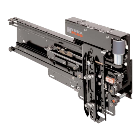
Linear car door 3201-Hydra Plus UD300 with toothed belt transmission (1) consisting in a plate (2) which supports the door drive
(3) and mounting of top tracks (4), transmission pulleys (5-6), as well as electronic assembly layout (7) and transformer (8).
The coupler (9) is attached to the toothed belt (1) for driving the door trucks (10-11) open and close.
5
7
82 1 6
11 10 4
3
9
Subject to change without notice!
EN
HYDRA PLUS UD300 CAR DOOR Code
Version
Code
Version
Date
Page
GM.2.002668.EN
B
3201.32.0397
B
04.02.2013
4.37
1.1 OPERATOR FIXING ON CAR ROOF
310
100 M2
22Sill
Fixing system
M1
LH HW = Min.40 - Max.180
ECO
MIDI
135
M1
180
02/C
TYP.
M2
32/R-L
105 SHEET
80
GLASS/GLASS-FRAMED
12/R-L 108 SHEET
93
GLASS/GLASS-FRAMED
98 SHEET
44/R 106 SHEET
02/C
TYP.
M3
32/R-L
65 SHEET
40 GLASS
12/R-L 65 SHEET
50 GLASS
65 SHEET
44/R 65 SHEET
M3
360
Subject to change without notice!
EN
HYDRA PLUS UD300 CAR DOOR Code
Version
Code
Version
Date
Page
GM.2.002668.EN
B
3201.32.0397
B
04.02.2013
5.37
TTyy..0022//CC
WITH GLASS PANELS
WITH SHEET PANELS WITH GLASS-FRAMED PANELS
Subject to change without notice!
EN
HYDRA PLUS UD300 CAR DOOR Code
Version
Code
Version
Date
Page
GM.2.002668.EN
B
3201.32.0397
B
04.02.2013
6.37
TTyy..1122//RR--LL
WITH GLASS PANELS
WITH SHEET PANELS WITH GLASS-FRAMED PANELS
Subject to change without notice!
EN
HYDRA PLUS UD300 CAR DOOR Code
Version
Code
Version
Date
Page
GM.2.002668.EN
B
3201.32.0397
B
04.02.2013
7.37
TTyy..4444//RRTTyy..3322//RR--LL
WITH SHEET PANELS WITH SHEET PANELS
Subject to change without notice!
EN
HYDRA PLUS UD300 CAR DOOR Code
Version
Code
Version
Date
Page
GM.2.002668.EN
B
3201.32.0397
B
04.02.2013
8.37
3. LANDING DOOR ALIGNMENT WITH CAR DOOR
The red buffer on top track fixing screw, represents the vertical reference for the position of all the landing and car doors.
While for the telescopic doors the red buffer indicates the door’s clear opening line, runby excluded, for central opening doors it
indicates the center of the clear opening.
2. FITTING AND ADJUSTING BRACKETS
3212.03.0078V01
3212.03.0078V02
HOLE THAT MUST
NOT BE COUNTED
AHW
40
50
60
70
80
90
100
110
120
130
140
150
160
170
180
15
14
13
12
11
10
9
8
7
6
5
4
3
2
1
B
23
22
21
20
19
18
17
16
15
14
13
12
11
10
9
Subject to change without notice!
EN
HYDRA PLUS UD300 CAR DOOR Code
Version
Code
Version
Date
Page
GM.2.002668.EN
B
3201.32.0397
B
04.02.2013
9.37
Fig. 1 Fig. 2
A
B
4. ASSEMBLY OF PANEL FIXING BOLTS
All panels must have at least two anchoring points.
For type 02/C, with rustproof panels, fit bolts as in figure 1, for panels with covering thicker than 1 mm fit bolts as in figure 2.
The “A” type conical washers should be placed on the top part of the door fixing profile.
The “B” type flat washer beneath.
WITH SHEET PANELS
WITH GLASS AND GLASS- FRAMED PANELS
WITH SHEET PANELS
TTYY0022//CCTTYY1122//RR--LL
TTYY3322//RR--LLTTYY4444//RR
Subject to change without notice!
EN
HYDRA PLUS UD300 CAR DOOR Code
Version
Code
Version
Date
Page
GM.2.002668.EN
B
3201.32.0397
B
04.02.2013
10.37
AB
WITH SHEET PANELS WITH SHEET PANELS
Subject to change without notice!
EN
HYDRA PLUS UD300 CAR DOOR Code
Version
Code
Version
Date
Page
GM.2.002668.EN
B
3201.32.0397
B
04.02.2013
11.37
Fig. 1 Fig. 2
A
B
5. CLEARANCE RECOVERING OF THE PANEL ASSEMBLING BOLTS
When the panels are hung to the hanger tracks the fixing screws should be placed according to figure (1).
For standard opening doors (up to 850 mm) the distance between the screws “B” is small compared to the clear opening height (at least 2
metres high).
This means that the clearance “A” can be varied by means of adjusting panel hanger bolts, which permits up to 30 mm of adjustment.
This can be avoided by installing panels as figure (2) during erection.
The panel height adjustment must be made after having effected the clearance recovering.
Standard position for the fixing screws of panel
hanger bolts at the time of assembling.
Position to be assumed by the fixing screws of panel
hanger bolts; in order to get it, please push the panel in
the direction of the opening.
Subject to change without notice!
EN
HYDRA PLUS UD300 CAR DOOR Code
Version
Code
Version
Date
Page
GM.2.002668.EN
B
3201.32.0397
B
04.02.2013
12.37
The shoe on the retaining pin is mounted with slight pressure until the proper tongues fit inside the groove (Fig. 1).
For the disassembling it is sufficient to push it from the rear side and at the same time with a small screw-driver to, part the
tongues (1) one after the other.
The shoe mounting and disassembling to the panel is very easy even with assembled panels: in fact it is enough to turn them 90
degrees, put them in a horizontal position (Fig. 2) and pull them towards the outside or push them into the sill’s groove.
The pin’s eccentricity and the presence of the slots allow considerable adjustment.
Fix bottom sliding shoes of the opening side as drawing Fig. 3, so that in case of breaking down of door panel the bottom shoe
can’t fall out from the sill channel.
>65
>65
Fig. 1 Fig. 2
1
SINGLE PLATED DOOR DOUBLE-PLATED DOOR
Fig. 3
6. BOTTOM SLIDING SHOES ASSEMBLY, MAINTENANCE AND REPLACEMENT
Each door must have at least two sliding blocks.
Check during maintenance that sliding guide shoes are present, securely fixed and have impermissible wear.
Subject to change without notice!
EN
HYDRA PLUS UD300 CAR DOOR Code
Version
Code
Version
Date
Page
GM.2.002668.EN
B
3201.32.0397
B
04.02.2013
13.37
For maximum admissible load see
specific documentation
7. FITTING CAR SILL BRACKETS
SILL
3201.05.5126
TTYY0022//CC
TTYY4444//RR
TTYY1122//RR--LL
SILL
SILL
3212.05.5188
3201.05.5056
Ty 12/R-L
TTYY3322//RR--LL
3201.05.5126
Ty 44/R
50 75
116
40
UNDERSILL
UNDERSILL
UNDERSILL
Subject to change without notice!
EN
HYDRA PLUS UD300 CAR DOOR Code
Version
Code
Version
Date
Page
GM.2.002668.EN
B
3201.32.0397
B
04.02.2013
14.37
7.1 ASSEMBLY OF SILL AND TOE GUARD
Insert the spire nut (1) into the sill support (3). Fix the sill (2) to the sill support (3) with the screws (4) and the bolts (5).
Rest the toe guard (6) on the undersill (3) and fasten by tightening screw (7).
SILL
3201.05.9061
UNDERSILL
TOE GUARD
7007.05.008
1
7
6
4
5
3
2
Subject to change without notice!
EN
HYDRA PLUS UD300 CAR DOOR Code
Version
Code
Version
Date
Page
GM.2.002668.EN
B
3201.32.0397
B
04.02.2013
15.37
TTyy..0011--0022//CCTTyy..1111--1122//RR--LL
TTyy..3311--3322//RR--LL
13
MAX.35
LOCK
ROLLERS
15
10 12
116 136
GUIDES
PLUMB
LINE
PLUMB
LINE
COUPLER
COUPLER
LOCK
ROLLERS
GUIDES
10 12
22
46 46
MAX.35
PLUMB
LINE
PLUMB
LINE
MIN.30M1 75
MAX.35
10
COUPLER
LOCK
ROLLERS
GUIDES
12
30 15
M1 90
PLUMB
LINE
PLUMB
LINE
TTyy..4433--4444//RR
10
COUPLER
LOCK
ROLLERS
GUIDES
12
45 15
75 90
PLUMB
LINE
PLUMB
LINE
MIN.30
MAX.35
MIN.30
MIN.30
8. PLACING THE MECHANISMS ON THE THRESHOLDS
Align to plumb with reference to the internal edge of the thresholds.
01-02/C
TYP.
M1
50
SHEET
75
GLASS/GLASS-FRAMED
11-12/R-L
75
SHEET
90
GLASS/GLASS-FRAMED
Subject to change without notice!
EN
HYDRA PLUS UD300 CAR DOOR Code
Version
Code
Version
Date
Page
GM.2.002668.EN
B
3201.32.0397
B
04.02.2013
16.37
9. FIXING OF THE COUPLER
After the assembly of the door panels proceed by fixing the coupler using the 3 screws (1) and the relevant belt-fixing systems (2).
2
1
DRIVE :
ECO/MIDI
Subject to change without notice!
EN
HYDRA PLUS UD300 CAR DOOR Code
Version
Code
Version
Date
Page
GM.2.002668.EN
B
3201.32.0397
B
04.02.2013
17.37
centre opening
side opening
min. 3 (D)
min. 3 (D)
min. 10 (D)
10. CAR DOOR LOCK
10.1 ASPECTS THAT MUST BE CHECKED DURING INSTALLATION AND MAINTENANCE
--MMaaiinntteennaanncceehhaassttoobbeeddoonneeaattlleeaassttoonneettiimmeeppeerryyeeaarr
- The car door lock must lock door if the car is out of unlocking zone. Lock hook must touch buffer.
- All parts of lock coupler, lock notch and additional lock notch (only centre opening) must be securely fixed ((AA)).
- Safety circuit must be interrupted if the door opens.
- Lock hook and beak overlap when lock is fully closed must be min. 10 mm ((BB))
- Gap between lock hook and notch should be 1-2 mm ((CC))
- Contacts should be clean and have minimal wear (metal visible)
- Lock hook and beak overlap when contact operates must be min. 7 mm
- The contact bridge should push the contact surface down min. 3 mm ((DD))
- Electrical terminations should be tight and secure.
- Contact bridge should be aligned to the middle of contact holes, not touching the hole edges.
min. 3 (D)
min. 10 (D)
1-2 (C)
1-2 (C)
Subject to change without notice!
EN
HYDRA PLUS UD300 CAR DOOR Code
Version
Code
Version
Date
Page
GM.2.002668.EN
B
3201.32.0397
B
04.02.2013
18.37
Ensure proper function of car door lock
- Check that lock hook is moving freely when pressing the lock vanes ((AA,,BB))
- Check that all bearing points of the car door lock are running smoothly with following method:
- Turn the POWER of the operator OFF !
- Move the door by hand on the belt to the completely close position - coupler must be fully retracted ((CC)).
- Release the belt, and check that the coupler is running itself (by spring force) to the completely extracted position. The lock
hook must remain during this operation in the fully locked position ((DD)).
- If the above mentioned test criteria are no longer fulfilled, the car door lock must be replaced.
To ensure a reliable function, the car door lock must be also replaced latest after
- 1 Million cycles or 5 years
C
CD
D
D
60 88
CD
AA
AA
BB
B

Other WITTUR Door Opening System manuals

WITTUR WSE 81 PLUS Series Assembly instructions

WITTUR

WITTUR WSE 81 PLUS Series Assembly instructions

WITTUR Hydra PLUS User manual

WITTUR

WITTUR Hydra PLUS User manual

Popular Door Opening System manuals by other brands

Helm MK-L 80 G 148 installation instructions

Helm

Helm MK-L 80 G 148 installation instructions

Henderson Bifold Fitting instructions

Henderson

Henderson Bifold Fitting instructions

Command access MLRK1 Series instructions

Command access

Command access MLRK1 Series instructions

HWH SPACEMAKER Operator's manual

HWH

HWH SPACEMAKER Operator's manual

Assa Abloy RIXSON W91DCP installation instructions

Assa Abloy

Assa Abloy RIXSON W91DCP installation instructions

Eco SR Basis 2 Fitting instructions

Eco

Eco SR Basis 2 Fitting instructions

Nice Pro-LT Instructions and warnings for installation and use

Nice

Nice Pro-LT Instructions and warnings for installation and use

GEZE Powerdrive PL-HT Pre-installation instructions

GEZE

GEZE Powerdrive PL-HT Pre-installation instructions

Aluprof AL-BR01 Installation, Assembly and Operating Manual

Aluprof

Aluprof AL-BR01 Installation, Assembly and Operating Manual

raumplus RIMA FINO Installation instruction

raumplus

raumplus RIMA FINO Installation instruction

Medva MAG-NET 800S instruction manual

Medva

Medva MAG-NET 800S instruction manual

RADEMACHER RolloPort S2 Translation of the Original Operating and Assembly Manual

RADEMACHER

RADEMACHER RolloPort S2 Translation of the Original Operating and Assembly Manual

DUCASSE INDUSTRIAL SEGMENTA TWIN TL installation instructions

DUCASSE INDUSTRIAL

DUCASSE INDUSTRIAL SEGMENTA TWIN TL installation instructions

DITEC DAB305 user manual

DITEC

DITEC DAB305 user manual

PortaPivot StealthPivot instruction manual

PortaPivot

PortaPivot StealthPivot instruction manual

Dormakaba FFT FLEX Green operating & maintenance manual

Dormakaba

Dormakaba FFT FLEX Green operating & maintenance manual

Ditec Entrematic PASAA2 manual

Ditec Entrematic

Ditec Entrematic PASAA2 manual

Benninca ESA BASIC manual

Benninca

Benninca ESA BASIC manual

manuals.online logo
manuals.online logoBrands
  • About & Mission
  • Contact us
  • Privacy Policy
  • Terms and Conditions

Copyright 2025 Manuals.Online. All Rights Reserved.