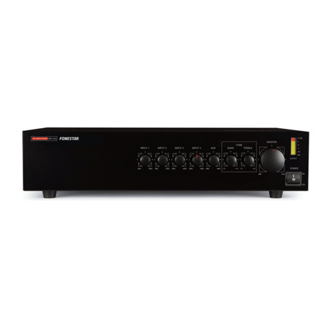
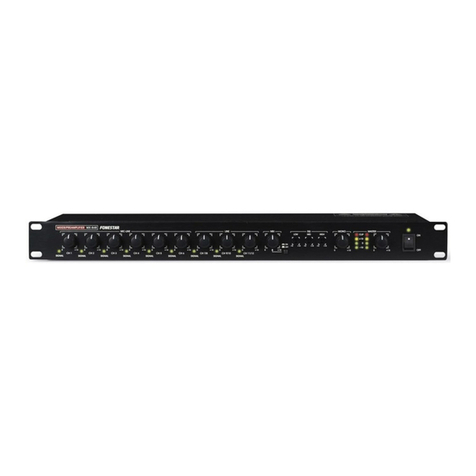
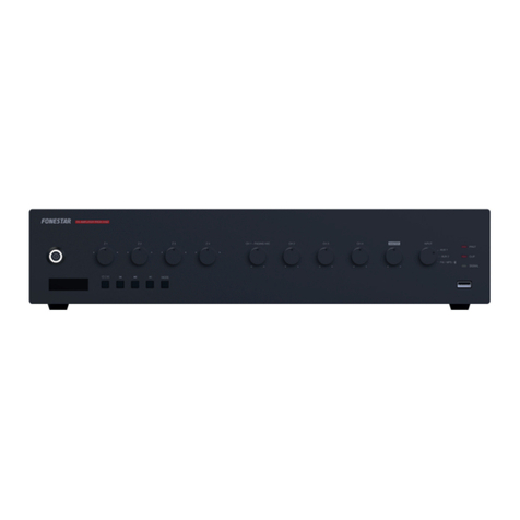
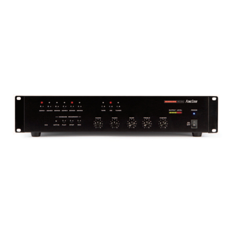
10.-LINE 1-4: set of controls for LINE 1-4 inputs.
GAIN: gain control for the input signal.
A, A+B, B: selector which allows you to choose the output or outputs that the signal is going to be sent
to.
LED input channel on indicator.
ON: push button which lets you activate or deactivate the input channel.
11.-ZONE VOL: volume control for the output signal.
12.-STEREO/MONO: push button to convert the output signal from a stereo output to 2 mono outputs.
13.-L/R: balance control wheel to send the stereo signal to the left (L) or right (R) channel.
14.-LED indicator to show the output signal level. Avoid the red zone (+6 db) staying alight, to avoid signal
saturation.
15.-BASS: control wheel to equalize the output signal bass frequencies. It is possible to achieve an
attenuation/enhancement of ±20 dB.
16.-MIDDLE: control wheel to equalize the output signal mid frequencies. It is possible to achieve an
attenuation/enhancement of ±15 dB.
17.-TREBLE: control wheel to equalize the output signal treble frequencies. It is possible to achieve an
attenuation/enhancement of ±14 dB.
18.-PHONES VOL: volume control wheel for the headphone output signal.
19.-Stereo headphone signal output to monitor the mix. 6.3 mm stereo jack connector.
20.-LED mixer on indicator.
21.-LED emergency signal detection (24 V DC) indicator.
REAR PANEL
1.- On/off switch.
2.- Power supply input to connect the 230 V AC/±15 V DC mains adapter.
3.- GND LIFT: selector to disconnect the mass from the earth in the system to avoid ground loops on
connecting the sound source.
4.- EMERG. 24 V DC: priority activation in the emergency input depending on signal level (24 V DC).
5.- ZONE B: balanced stereo output through 6.3 mm stereo jack connector.
6.- ZONE A: balanced stereo output through XLR connector.
7.- MASTER LEVEL: control allowing you to choose among 5 maximum output levels, to adapt the output
signal to the amplifier sensitivity or the power amplifier whichever either of the two outputs are going to
be connected to. It is possible to choose among 0.245 V, 0.775 V, 1.25 V, 1.5 V and 2.5 V.
8.- ZONE A: unbalanced stereo output through 2 x RCA connector.
9.- ZONE B: unbalanced stereo output through 2 x RCA connector.
10.- EMERG: input for the emergency signal which is sent to the output when a 24 V DC signal is detected
in the EMERG. 24 V DC terminals. On activating priority in this signal, the rest of the inputs are
automatically silenced and the message is reproduced in all output zones.
11.- LINE 1-4: unbalanced line level inputs. 2 x RCA connector.
12.- EMERGENCY LEVEL: volume control for the signal connected to the EMERG input.
13.- GND: reference terminal for connecting the earths from other equipment if necessary.
14.- MIC 3: microphone input with combo connector (XLR and 6.3 mm stereo jack). Balanced and
unbalanced microphone signals and dynamic or condenser microphones can be connected. If phantom
power supply is needed, the mixer itself supplies 15 V DC through the XLR connector activating the
phantom selector corresponding to the MIC 3 input.
- 5-
EN
