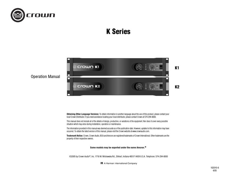
Crown CROWN K Series User manual

102010-1
4/97
KK
KK
K-Series-Series
-Series-Series
-Series
FCC COMPLIANCE NOTICE
This equipment has been tested and found to com-
ply with the limits for a Class A digital Device, pursu-
ant to Part 15 of the FCC Rules. These limits are
designed to provide reasonable protection against
harmful interferencewhentheequipment is operated
in a commercial environment. This equipment gener-
ates, uses and can radiate radio frequency energy
and, if not installed and used in accordance with the
instruction manual, may cause harmful interference
to radio communications. Operation of this equip-
ment in a residential area is likely to cause harmful
interferencein whichcase theuser will be requiredto
correct the interference at his own expense.
“The user is cautioned that any changes or modifica-
tions not expressly approved by Crown International
could void the user’s authority to operate the equip-
ment.”
© 1997 by Crown International, Inc., P.O. Box 1000,
Elkhart, IN 46515-1000 U.S.A. Telephone: 219-294-8000.
Fax: 219-294-8329. Trademark Notice:
Balanced Current
Amplifier
™,and
BCA
™are trademarks and
Crown
®is a
registered trademark of Crown International, Inc. Other
trademarks are the property of their respective owners.

Page 2
K-Series BalancedCurrentAmplifier™
Read all safety and oper-
ating instructions before
operating the K-Series
amplifier. Follow all
instructions carefully and
heed any warnings given.
Hi! I'm Mick, I'll
be giving you the
details about your
new K-Series Amp!!
ObtainassistancefrObtainassistancefr
Obtainassistancefromqualifiedseromqualifiedser
omqualifiedserom qualified ser
omqualifiedservicevice
vicevice
vice
personnelifanyofthefollowingoccurs:personnelifanyofthefollowingoccurs:
personnelifanyofthefollowingoccurs:
• The power cord or plug has been
damagedin any way.
• Foreignobjectsor liquidhasfalleninto
theamplifierenclosure.
• The amplifier has been exposed to
rain or has been partially or totally
immersed in any liquid.
• Theamplifier hasbeendropped orthe
chassis has been damaged.
• You notice a marked change in per-
formance,oryour K-Series ampother-
wise does not appear to operate
normally.
CAUTION:
Do not locate sensitive,
high-gain equipment such
as preamplifiers or tape
decks directly above or be-
low the unit. If an equip-
ment rack is used, we
recommend locating the
amplifier(s) in the bottom of
the rack and the preampli-
fier or other sensitive equip-
ment at the top.
Friendly Page
of Tips and
Warnings
Keep your K-Series amplifier
away from sources of heat,
such as a radiator or oven.
Do not cover or surround your
amp with material which may
retain heat, such as a
blanket or curtain.
Important:
Driving heavy loads for sustained periods of time
may cause parts of the amplifier’s case to reach
temperatures which will be hot to touch. But don’t
be alarmed.The amplifier’s internal protection
circuitry ensures maximum temperature levels will
remain well below any level that might be
harmful to the amplifier.

Page 3
K-Series BalancedCurrentAmplifier™
Do not drop or
spill any foreign
(or domestic)
object or liquid
into the K-Series
amplifier.
Do not attempt
to service this
unit beyond
instructions
contained in
this manual.
Refer
all other
servicing to
the Crown
Service
Department.
Protect the power
cord attached to
your K-Series am-
plifier. Route it to
avoid foot traffic
or other situations
where the cord
might be stretched
or pinched. Pay
special attention to
the cord connector
and attachment
points.
Clean your
K-Series amp
only with a
damp cloth!
Keeptheseinstructions
for future reference.
DONOTBYPASSORDEFEATTHE
GROUNDINGORPOLARIZATIONMEANS
USED ON THE K-SERIES AMPLIFIERS.
MAKESUREALL BLADES ONTHE
POLARIZEDPOWERPLUGCANBEFULLY
INSERTED INTO THE EXTENSION CORD,
RECEPTACLEOR OTHER OUTLETTHAT
WILL BE USED WITH THE UNIT.
WARNING: Shock hazard.To reduce
the risk of fire or electric shock, do
not expose this unit to rain or mois-
ture. Do not immerse your K-Series
amplifier in any liquid. Do not operate
your amplifier near a pool, bathtub or
other standing water.

Page 4
K-Series BalancedCurrentAmplifier™
Unpacking Your
K-Series Amp
Please unpack and inspect your amplifier for any damage that
may have occurred during transit. If damage is found, notify
the transportation company immediately. Only you can initiate
a claim for shipping damage. Crown will be happy to help as
needed. Save the shipping carton as evidence of damage for
the shipper’s inspection.
We also recommend that you save all packing materials so
youwillhavethemifyoueverneedtotransporttheunit.NEVER
SHIPTHE UNITWITHOUTTHE FACTORY PACK.

Page 5
K-Series BalancedCurrentAmplifier™
K-Series Features List:
Here are some of the more exciting features of your K-Series
Amplifier:
Accurate, uncolored sound with very low distortion for
the best in music and voice reproduction.
High damping factor for tight, clean bass response.
Advanced design for energy conservation.
Mono mode switches allow you to set up your amps/speakers in
the configuration that best suits your needswith combined
amp inputs, combined amp outputs, or both.
Advanced protection circuitry guards against: shorted outputs,
open circuits, DC, mismatched loads, general overheating,
high-frequency overloads and internal faults.
Extemely versatile, handling a wide range of speaker impedances
and outputs.
Exclusive BCA design provides super efficiency for quiet,
fan-free operation.
Switchable input sensitivity.
Soft start feature prevents the K-Series Amplifier from
drawing large currents when it is first turned on. This means
you dont need to delay power-on of your amps.
Can be mounted in standard (19-inch (48.3-cm)) rack or stacked
on top of each other. Uniquely molded, cast-aluminum front
panel provides exceptional air circulation even when your K-
Series amplifiers are stacked.
The best three year No-Fault full warranty in the business!
It even covers round-trip ground shipping in the U.S. for all
warranty work.
Done!

Page 6
K-Series BalancedCurrentAmplifier™
Quick Start!
Firstthingsfirst. Weknowyoujustcan’twaitto
crank up your new Crown®
K-Series
ampli-
fier. And the last thing you want to do is dig
through pages of tech-talk to find out where
the “ON” switch is. So that’s why we provided
you with this quick and simple page to get you
up and running right away. Just take a few minutes
to read through this—no more than five or ten, max—
you’ll be glad you did.
1. Make sure the
KSeries
amp and all other equipment is
turned OFF before you begin wiring. The amp power
switch, which is located on the far right side of the front
panel, is “OFF” when pressed downward.
2. Mount your
K-Series
amp securely in the rack, or position
it on a solid surface.
3. Connect the left and right inputs coming from your mixer,
preamp, or other processor. You can use either balanced
1/4-inch phone or 3-pin XLR connectors. You can also
choose to run in MONO mode, with either bridged out-
puts, “Y” inputs, or both. If so, see the sections starting
on page 15 for further instructions.
4. Connect the output wiring (left and right speakers).
5. Connect your
K-Series
amp and other equipment to the
appropriate power source.
6. Turn on your mixer, preamp, signal processor, or any
other equipment in your system EXCEPT your
K-Series
amplifier. (Remember: save the best for last.)

Page 7
K-Series BalancedCurrentAmplifier™
7. Make sure the Channel 1 and Channel 2 level (volume)
controls on your
K-Series
amplifier are turned all the way
down (counter-clockwise), then flip the power switch
“ON” (press upward). Note: After a two-second delay, the
“Enable” light will glow a bright green to indicate power is
on. If no audio signal is present at the amp, the enable
light will then switch to a dim green.
8. (Now comes the fun!) Supply input, adjust amp levels
and enjoy.
CAUTION: Excessive output levels may toast your speakers.
Crown’s
K
-Series amplifier has such low distortion, you may
not realize the actual level being reached until it’s too late.
Please exercise caution and drive your speakers responsibly,
or at least warn your neighbors!
Typical Stereo
Hookup
OFFON
BRIDGE
OUTPUT
OFFON
“Y” INPUT
MONO MODES
BALANCED INPUT WIRING FUSE
CAUTION:
TO PREVENT ELECTRIC SHOCK DO NOT
REMOVE
BOTTOM COVER. NO USER SERVICEABALE PARTS INSIDE.
REFER SERVICING TO QUALIFIED SERVICE PERSONNEL.
WARNING:
TO REDUCE THE RISK OF
FIRE
OR ELECTRIC SHOCK, DO NOT EXPOSE
20 A @ 100-120 VAC
10 A @ 200-240 VAC
26 dB1.4V
INPUT
SENSITIVITY
26 dB1.4V
INPUT
SENSITIVITY
CH-2 INPUTS CH-1 INPUTS
321
GND
OUTPUTS
CH-2 CH-1
OUTPUT WIRING
STEREO BRIDGE-MONO
THIS DEVICE COMPLIES WITH PART 15 OF THE FCC RULES.
OPERATION IS SUBJECT TO THE FOLLOWING CONDITIONS:
1) THIS DEVICE MAY NOT CAUSE HARMFUL
INTERFERENCE.
PUSHPUSH
Studio Monitors or Speaker Stacks
+
-
-+
Ch. 1
26 dB1.4 V
INPUT
SENSITIVITY
Mixer
OFFON
BRIDGE
OUTPUT
OFFON
"Y" INPUT
26 dB1.4 V
INPUT
SENSITIVITY
Ch. 2
-
+
+
-
Ch. 1
Ch. 2
or
or

Page 8
K-Series BalancedCurrentAmplifier™
What
Am I
Gonna do
With All
These
Cables??

Page 9
K-Series BalancedCurrentAmplifier™
Contents
Friendly Page of Tips and Warnings ..................... 2
Unpacking Your
K-Series
Amplifier....................... 4
Features................................................................ 5
Quick Start ............................................................ 6
1 Welcome ............................................................ 10
2 Very Detailed Install ............................................ 14
3 Operation............................................................ 21
4 Other Issues........................................................ 25
5 Specifications ..................................................... 29
6 Service ............................................................... 34
Illustrations
Typical Stereo Hookup .......................................... 7
1.1 The
K-Series
Amplifier ................................... 10-11
1.2 The Big Picture: Controls, Indicators and
Connectors ................................................... 12-13
2.1 Mounting Dimensions ......................................... 14
2.2 Mono Mode Switches ......................................... 15
2.3 Input Sensitivity Switch ....................................... 15
2.4 Typical Input Wiring ............................................ 16
2.5 Stereo Output Wiring ........................................... 17
2.6 Bridge Mono Output Wiring ................................ 18
2.7 Stereo Hookup .................................................... 19
2.8 Bridged-Mono Output Hookup............................ 19
2.9 “Y” Mono Input Hookup ...................................... 20
2.10 “Y” Mono Input / Bridged Output ......................... 20
3.1 Front Panel Indicators & Controls........................ 21
3.2 Back Panel Controls ........................................... 23
3.3 Back Panel Fuse Location .................................. 24
4.1 Balanced & Unbalanced Input Wiring ................ 26
4.2 Balanced Input Wiring ........................................ 27
4.3 Unbalanced Input Wiring.................................... 28
5.1 Awesome Frequency (Amplitude) Response ..... 33
5.2 Superior Damping Factor.................................... 33

Page 10
K-Series BalancedCurrentAmplifier™
Thank you for choosing Crown! Mick and his team of enthusi-
astic engineers have worked long hours to craft a totally new
kind of amplifier—the
K-Series.
These are the first Balanced
CurrentAmplifier™(BCA™),andweare all very proud tohave
invented them. Our Balanced Current Amplifier makes use of
a special type of circuitry which allows high levels of power
output without all of the associated heat you find in a conven-
tional amplifier. And that’s very good news for you!
How high is the power output? The
K1
amplifier produces an
impressive 1,500 watts and weighs only 32 pounds, while the
K2
produces a whopping 2,500 watts while weighing only 38
pounds; both without using a cooling fan!* Of course, the ab-
sence of a cooling fan means your amp runs quieter (no fan
noise) and cleaner (no need for filters) and requires very little
maintenance (we
thought
you’d like that).
* 1,500 watts and 2,500 watts total from both channels (for the
K1
and
K2
respectively; 750 and 1,250 watts per channel). See the Specifications
section for details.
1 Welcome
BALANCED CURRENT AMPLIFIER
BALANCED CURRENT AMPLIFIERBALANCED CURRENT AMPLIFIERBALANCED CURRENT AMPLIFIER

Page 11
K-Series BalancedCurrentAmplifier™
Fig. 1.1
The K-2 Amplifier
(K-1 Amplifier
appears the same
except for
nameplate)
The
K-Series
amplifiers arealsohighlyenergy-efficient—some
of the World’s first “green” amps. As a result, the
K-Series
amps use less electricity (reducing your utility bills) and save
the precious resources of our environment.
And that’s not all! Your
K-Series
amp can drive an amazing
range of loudspeakers, making it one of the most versatile
amplifiers ever. Plus, your
K-Series
has one of our most so-
phisticated(and totallyautomatic) protection systems,so your
amplifierwill keepworkinglongafterotheramplifiershaveshut
down. It’s part of our philosophy:
Your show must go on!
This manual will help you correctly set up and use your new
amplifier—we strongly recommend you read all instructions,
warnings and cautions. Also, for your protection, please send
in your warranty registration card today. And save your bill of
sale—it’syourofof
ofof
officialprficialpr
ficialprficialpr
ficialproofofpuroofof pur
oofof puroofof pur
oofof purchase.chase.
chase.chase.
chase.
Enable
Clip
Signal
IOC
2
Enable
Clip
Signal
IOC
2
1
0dB
3
1
5
7
9
11
13
15
17
19
21
25
45
30
100
11
0dB
3
1
5
7
9
11
13
15
17
19
21
25
45
30
100
1
0dB
3
1
5
7
9
11
13
15
17
19
21
25
45
30
100 0 dB
3
1
5
7
9
11
13
15
17
19
21
25
45
30
100
TLCTLC

Page 12
K-Series BalancedCurrentAmplifier™
Fig. 1.2
The Big Picture:
Controls,
Indicators &
Connectors
BALANCED CURRENT AMPLIFIER
BALANCED CURRENT AMPLIFIERBALANCED CURRENT AMPLIFIER
OFFON
BRIDGE
OUTPUT
OFFON
“Y” INPUT
MONO MODES
BALANCED INPUT WIRING CAUTION: TO PREVENT ELECTRIC SHOCK DO NOT REMOVE
BOTTOM COVER. NO USER SERVICEABALE PARTS INSIDE.
REFER SERVICING TO QUALIFIED SERVICE PERSONNEL.
ATTENTION: DÉBRANCHER AVANT D'OUVRIR.
2
1
26dB1.4V
INPUT
SENSITIVITY
26dB1.4V
INPUT
SENSITIVITY
CH-2 INPUTS CH-1 INPUTS
321
GND
THIS DEVICE COMPLIES WITH PART 15 OF THE FCC RULES.
OPERATION IS SUBJECT TO THE FOLLOWING CONDITIONS:
1) THIS DEVICE MAY NOT CAUSE HARMFUL INTERFERENCE.
2) THIS DEVICE MUST ACCEPT ANY INTERFERENCE THAT
MAY CAUSE UNDESIRED OPERATION.
PUSHPUSH
Removable
Rack Handle
Ch-2 Balanced
Phone Jack In
p
ut Ch-1 Balanced
Phone Jack In
p
ut
Ch-2 Balanced
XLR In
p
ut Ch-1 Balanced
XLR In
p
ut
Ch-1 Input
Sensitivity Switch
Ch-2 Input
Sensitivity Switch Mono Mode
Switches
Way Cool
Logo
The Company that invented
Balanced Current Amplifiers
Hand-crafted Cast
Aluminum Front Panel

Page 13
K-Series BalancedCurrentAmplifier™
Enable
Clip
Signal
IOC
2
Enable
Clip
Signal
IOC
2
10dB
3
1
5
7
9
11
13
15
17
19
21
25
45
30
100 110dB
3
1
5
7
9
11
13
15
17
19
21
25
45
30
100 10 dB
3
1
5
7
9
11
13
15
17
19
21
25
45
30
100 0 dB
3
1
5
7
9
11
13
15
17
19
21
25
45
30
100
FUSE WARNING: TO REDUCE THE RISK OF FIRE
OR ELECTRIC SHOCK, DO NOT EXPOSE
THIS EQUIPMENT TO RAIN OR MOISTURE.
2
0 A @ 100-120 VAC
1
0 A @ 200-240 VAC
OUTPUTS
CH-2 CH-1
OUTPUT WIRING
STEREO BRIDGE-MONO
Ch-1 Level
Control Ch-2 Level
Control
TLC, Clip, IOC
& Signal Indicators Enable
Indicator
Power Switch
Fuse
Power Cable
5-Way Binding
Post Out
p
uts Remove these screws to
remove the Rack Handles
TLCTLC
Note:K1amplifierandCE(European)versionsofboth amplifiers feature identical front and back
panel layouts except for product nameplates and fuse specifications.

Page 14
K-Series BalancedCurrentAmplifier™
2 Very Detailed Install
Follow these instructions for a detailed explanation of
K-Se-
ries
installation procedures and options. If you just want to get
up and running as quickly as possible, see the Quick Start
section on page 6.
1. Begin with the amplifier turned off and disconnected
from the power receptacle. The
K-Series
power switch
is located on the right side of the front panel; it is OFF
when depressed downward. Equipment that will be con-
nected to the inputs of the amplifier (such as mixers or
preamplifiers) should also be turned off.
2. Mount the amplifier. Your
K-Series
amp can be mounted
in a standard, 19-inch (48.3-cm) equipment rack, or it can
be simply stacked with other equipment. The amp has a
unique front-panel design which provides exceptional
air circulation between
K-Series
amps, even when they
are stacked directly on top of each other. This feature
makes it easy to keep your amplifiers cool. (See the sec-
tion "You Gotta Know When To Kool It!" on page 25 for
hints on amplifier cooling.)
Fig. 2.1
Mounting
Dimensions
If your choose to mount your amp in a rack, you should
secure the back of the rack as well as the front. Even
though the amp’s center of gravity is toward the front, se-
curing the amp at both front and rear will assure that the
amp stays in place, even when the rack is transported.
19 in
48.3 cm
16 in
40.6 cm
3.5 in
8.9 cm
3 in
7.62 cm
SIDE VIEW
BALANCED CURRENT AMPLIFIER
BALANCED CURRENT AMPLIFIERBALANCED CURRENT AMPLIFIERBALANCED CURRENT AMPLIFIER
Enable
Clip
Signal
IOC
2
Enable
Clip
Signal
IOC
2
1
0dB
3
1
5
7
9
11
13
15
17
19
21
25
45
30
100
11
0dB
3
1
5
7
9
11
13
15
17
19
21
25
45
30
100
1
0dB
3
1
5
7
9
11
13
15
17
19
21
25
45
30
100 0 dB
3
1
5
7
9
11
13
15
17
19
21
25
45
30
100
Need to draw
side view
TLC
TLC

Page 15
K-Series BalancedCurrentAmplifier™
3. Set the mono mode switches. Both the Bridge Output
and “Y” input switches should be in the OFF position
when you’re running in Stereo Mode. Stereo Mode allows
independent inputs on the right and left channels to feed
separate speakers at the output. It’s the configuration
typically chosen for everyday audio applications.
OFFON
BRIDGE
OUTPUT
OFFON
“Y” INPUT
MONO MODES
S
C
H
Fig. 2.2
Mono Mode
Switches
26dB1.4V
INPUT
SENSITIVITY
Fig. 2.3
Input Sensitivity
Switch
Turn theBridgeOutput switch toON to haveasingle input
that feeds to a single output with twice the voltage of Ste-
reoMode.Usethisconfigurationifyouwanttogiveupstereo
capabilitiesinorderto drive your speakers
louder.
(Youmight
also choose to use this configuration if you are running a dis-
tributed sound system from the
K-Series
amp
.
)
Turn the “Y” input switch to ON if you want both inputs to
be connected in parallel. Use this configuration if you
want a common audio signal to feed out to two channels,
eachhaving its ownlevelcontrol.You mightusethis setup
if you’re running to a monitor speaker on one channel and
a main speaker stack on the other channel.
You may also want to configure your system to take ad-
vantage of both the Bridge Output and “Y” input capabili-
ties. This would allow you to have daisy-chained inputs
fed to a double-the-voltage output. (See further instruc-
tions on daisy-chained inputs in the discussion on con-
necting the inputs in step 5 in this section.)
4. Set the Input Sensitivity switches of each channel to
the desired setting. Two choices are available: 1.4 V for
full rated output, or a fixed voltage gain of 26 dB. (The
K-
Series
ship from the factory with default settings of 1.4 V,
which translates to approximately 33 dB of gain.)

Page 16
K-Series BalancedCurrentAmplifier™
If the Bridge Output switch is ON, only the Channel 1 in-
put connectors should be used. If only the “Y” input
switch is ON, then either set of connectors can be used.
5. Connect the inputs of the
K-Series
amp to your mixer,
preamplifier, or other equipment ahead of the amp. Two
types of balanced input connectors are provided, allow-
ing you to choose either 1/4-inch phone or 3-pin XLR con-
nectors. You can also choose to use either balanced or
unbalanced wiring. (See the section Balancing the Line
on page 26 for an explanation of balanced vs. unbal-
anced wiring.)
OFFON
BRIDGE
OUTPUT
OFFON
“Y” INPUT
MONO MODES
26dB1.4V
INPUT
SENSITIVITY
26dB1.4V
INPUT
SENSITIVITY
CH-2 INPUTS CH-1 INPUTS
PUSHPUSH
CH-2 CH-1
Input Wiring Tips
1. For all input connectivity, use shielded wire only. Cables with a
foil wrap shield or a high-density braid are superior. Cables with
a stranded spiral shield, although very flexible, will break down
over time and cause noise problems.
2. Try to avoid using unbalanced lines with professional equip-
ment. If you have no choice, keep the cables as short as pos-
sible. (Refer to the section Balancing the Line on page 26.)
3. To minimize hum and crosstalk, avoid running low-level input, high-level output and AC
power feeds in the same path. Try to run differing signal paths at 90° to one another. If
you must use a common path for all cables, use a star-quad cable for the low-level
signals.
4. When changing input connectors or wiring, turn the amplifier level controls all the way
down (counter-clockwise).
5. When changing output connections, a professional will turn the amplifier level down and
the AC power off to minimize the chance of short-circuiting the output.
Fig. 2.4
Typical Input
Wiring

Page 17
K-Series BalancedCurrentAmplifier™
If you are running with both the Y-Input and Bridge Output
switches "ON", you may choose to make use of the un-
used input connectors as daisy-chain outputs—perhaps
to other amplifiers in your system. For instance, if you’re
running in “Y” mono mode and you connect the input sig-
nal to the Channel 1 XLR connector, you can use the
Channel 2 XLR connector plus the two 1/4-inch phone
plugs for daisy-chained outs. This simplifies your wiring
needs, making good use of all the components in your
system.
OUTPUTS
CH-2 CH-1
+
–
+
–
Fig. 2.5
Stereo Output
Wiring
6. Connect the outputs of the
K-Series
amp to your loud-
speakers. If the Bridge Output switch is turned OFF, con-
nect the positive (+) and negative (–) leads of each
loudspeaker to the appropriate Channel 1 and Channel 2
output connectors as shown in Figure 2.5.
Output Wiring Tips
1. To prevent possible short circuits, wrap or otherwise insu-
late exposed loudspeaker cable connectors.
2. Do not use connectors that might accidentally tie conduc-
tors together when making or breaking the connection
(for example, a standard, 1/4" stereo phone plug).
3. Never use connectors that could be plugged into AC power sockets. Accidental
AC input will be an electrifying experience for your equipment. But you will find out
real quick if your speakers are any good at 60 Hz!
4. Avoid using connectors with low current-carrying capacity, such as XLRs.
5. Do not use connectors that have any tendency to short.

Page 18
K-Series BalancedCurrentAmplifier™
If the Bridge Output switch is turned ON, connect a mono
load across the red binding posts of each channel as
shown in Figure 2.6. Do NOT use the black binding
posts when the Bridge Output switch is turned on.
OUTPUTS
CH-2 CH-1
+
–
Fig. 2.6
Bridge Mono
Output Wiring
Notice that the Channel 1 red binding post is positive (+)
and the Channel 2 red binding post is negative (–) when
the Bridge Output switch is turned on. The black binding
posts should not be used.
Never short or parallel the output channels of a
K-Series
amplifier to itself or to any other amplifier.
Detailed diagrams of the four possible input-to-output
configurations (stereo, bridged-mono, “Y” mono, and “Y”
inputto bridged-mono) areshown onthefollowing pages.
7. Turn on all equipment ahead of the amplifier such as
the mixer or preamplifier. Adjust their signal levels to their
optimum "signal to noise" settings.
8. Plug the amplifier into the power receptacle, turn on
the amplifier and adjust its level controls to a desired
setting. See instructions on page 22 if this is the first time
the amplifier is being turned on.
The Next Couple of
Pages Show Some
Typical Hook-up
Options...

Page 19
K-Series BalancedCurrentAmplifier™
Fig. 2.7
Stereo Hookup—
two stacks, one
amp, stereo in,
stereo out.
Fig. 2.8
Bridged-Mono
Output Hookup—
mono or stereo In,
mono out—great for
subs...or when you
want it LOUD!
OFFON
BRIDGE
OUTPUT
OFFON
“Y” INPUT
MONO MODES
BALANCED INPUT WIRING FUSE
CAUTION:
TO PREVENT ELECTRIC SHOCK DO NOT
REMOVE
BOTTOM COVER. NO USER SERVICEABALE PARTS INSIDE.
REFER SERVICING TO QUALIFIED SERVICE PERSONNEL.
WARNING:
TO REDUCE THE RISK OF
FIRE
OR ELECTRIC SHOCK, DO NOT EXPOSE
20 A @ 100-120 VAC
10 A @ 200-240 VAC
26 dB1.4V
INPUT
SENSITIVITY
26 dB1.4V
INPUT
SENSITIVITY
CH-2 INPUTS CH-1 INPUTS
321
GND
OUTPUTS
CH-2 CH-1
OUTPUT WIRING
STEREO BRIDGE-MONO
THIS DEVICE COMPLIES WITH PART 15 OF THE FCC RULES.
OPERATION IS SUBJECT TO THE FOLLOWING CONDITIONS:
1) THIS DEVICE MAY NOT CAUSE HARMFUL
INTERFERENCE.
PUSHPUSH
Studio Monitors or Speaker Stacks
+
-
-+
Ch. 1
26 dB1.4 V
INPUT
SENSITIVITY
Mixer
OFFON
BRIDGE
OUTPUT
OFFON
"Y" INPUT
26 dB1.4 V
INPUT
SENSITIVITY
Ch. 2
-
+
+
-
Ch. 1
Ch. 2
or
or
Sub-Woofer
OFFON
BRIDGE
OUTPUT
OFFON
“Y” INPUT
MONO MODES
BALANCED INPUT WIRING FUSECAUTION: TO PREVENT ELECTRIC SHOCK DO NOT
REMOVE
BOTTOM COVER. NO USER SERVICEABALE PARTS INSIDE.
REFER SERVICING TO QUALIFIED SERVICE PERSONNEL.
WARNING: TO REDUCE THE RISK OF
FIRE
OR ELECTRIC SHOCK, DO NOT EXPOSE
20 A @ 100-120 VAC
10 A @ 200-240 VAC
26 dB1.4 V
INPUT
SENSITIVITY
26 dB1.4 V
INPUT
SENSITIVITY
CH-2 INPUTS CH-1 INPUTS
321
GND
OUTPUTS
CH-2 CH-1
OUTPUT WIRING
STEREO BRIDGE-MONO
THIS DEVICE COMPLIES WITH PART 15 OF THE FCC RULES.
OPERATION IS SUBJECT TO THE FOLLOWING CONDITIONS:
1) THIS DEVICE MAY NOT CAUSE HARMFUL
INTERFERENCE.
PUSHPUSH
+
+
Ch. 1
26 dB1.4 V
INPUT
SENSITIVITY
OFFON
BRIDGE
OUTPUT
OFFON
"Y" INPUT
26 dB1.4 V
INPUT
SENSITIVITY
-
-
Ch. 1
Do Not Use
Black Terminals
or
Mixer

Page 20
K-Series BalancedCurrentAmplifier™
Fig. 2.9
"Y" Mono Input
Hookup—Great
for when you want
independent level
controls for
monitors and main
stacks
Fig. 2.10
"Y" Mono Input to Bridged-Mono Output
Hookup—When you want plenty of power
such as running a sub-bass and you
need to daisy chain the input signal.
OFFON
BRIDGE
OUTPUT
OFFON
“Y” INPUT
MONO MODES
BALANCED INPUT WIRING FUSE
CAUTION:
TO PREVENT ELECTRIC SHOCK DO NOT
REMOVE
BOTTOM COVER. NO USER SERVICEABALE PARTS INSIDE.
REFER SERVICING TO QUALIFIED SERVICE PERSONNEL.
WARNING:
TO REDUCE THE RISK OF
FIRE
OR ELECTRIC SHOCK, DO NOT EXPOSE
20 A @ 100-120 VAC
10 A @ 200-240 VAC
26 dB1.4V
INPUT
SENSITIVITY
26 dB1.4V
INPUT
SENSITIVITY
CH-2 INPUTS CH-1 INPUTS
321
GND
OUTPUTS
CH-2 CH-1
OUTPUT WIRING
STEREO BRIDGE-MONO
THIS DEVICE COMPLIES WITH PART 15 OF THE FCC RULES.
OPERATION IS SUBJECT TO THE FOLLOWING CONDITIONS:
1) THIS DEVICE MAY NOT CAUSE HARMFUL
INTERFERENCE.
PUSHPUSH
+
-
-+
Ch. 1
26 dB1.4 V
INPUT
SENSITIVITY
OFFON
BRIDGE
OUTPUT
OFFON
"Y" INPUT
26 dB1.4 V
INPUT
SENSITIVITY
Ch. 2 -
+
+
-
Ch. 1
Ch. 2
or
Studio Monitors or Speaker StacksMixer
OFFON
BRIDGE
OUTPUT
OFFON
“Y” INPUT
MONO MODES
BALANCED INPUT WIRING FUSE
CAUTION:
TO PREVENT ELECTRIC SHOCK DO NOT
REMOVE
BOTTOM COVER. NO USER SERVICEABALE PARTS INSIDE.
REFER SERVICING TO QUALIFIED SERVICE PERSONNEL.
WARNING:
TO REDUCE THE RISK OF
FIRE
OR ELECTRIC SHOCK, DO NOT EXPOSE
20 A @ 100-120 VAC
10 A @ 200-240 VAC
26 dB1.4V
INPUT
SENSITIVITY
26 dB1.4V
INPUT
SENSITIVITY
CH-2 INPUTS CH-1 INPUTS
321
GND
OUTPUTS
CH-2 CH-1
OUTPUT WIRING
STEREO BRIDGE-MONO
THIS DEVICE COMPLIES WITH PART 15 OF THE FCC RULES.
OPERATION IS SUBJECT TO THE FOLLOWING CONDITIONS:
1) THIS DEVICE MAY NOT CAUSE HARMFUL
INTERFERENCE.
PUSHPUSH
+
+
26 dB1.4 V
INPUT
SENSITIVITY
OFFON
BRIDGE
OUTPUT
OFFON
"Y" INPUT
26 dB1.4 V
INPUT
SENSITIVITY
-
-
Ch. 1
Do Not Use
Black Terminals
Ch. 1Ch. 2
or
or
Auxiliary Output for
daisy-chaining, etc.
Sub-WooferMixer
Other manuals for CROWN K Series
4
Table of contents
Other Crown Amplifier manuals

Crown
Crown D-40 User manual

Crown
Crown PL-3 User manual

Crown
Crown CH1 User manual

Crown
Crown CTs 600 User manual

Crown
Crown CL1 User manual

Crown
Crown Com-Tech CT-810 User manual

Crown
Crown CE-1000A Manual

Crown
Crown Macro-Tech MA-5000VZ Quick start guide

Crown
Crown 800 CSL User manual

Crown
Crown ce 4000 User manual

Crown
Crown CP660 User manual

Crown
Crown XS900 User manual

Crown
Crown CTs 2-Channel User manual

Crown
Crown CDi 1000 User manual

Crown
Crown PT 3.1 User manual

Crown
Crown 133472-1A User guide

Crown
Crown POWER BASE 1 User manual

Crown
Crown COMMERCIAL AUDIO SERIES User manual

Crown
Crown I-Tech HD User manual

Crown
Crown CTs 2000 Parts list manual