CRP Securities CAL-ROYAL Grade1 Technical specifications

Installation and Programming Instructions for Electronic Stand-Alone Cylindrical Locks
Installation and Programming Instructions
Stand-alone Touchscreen Access Lock
ANSI/BHMA Grade1
Take the time to read through this guide to familiarize yourself with the features and operation
of the lock, and its quick and easy programming procedures.
Save this PROGRAMMING INSTRUCTIONS for future reference.
■
Note
: Improper installations may result in damage to the lock and void the factory warranty.


Installation and Programming Instructions for Electronic Stand-Alone Cylindrical Locks
- 2 -
Warning:
Changes or modifications to this unit not expressly approved by the party
responsible for compliance could void the user's authority to operate the equipment.
INSTALLATION GUIDE
TABLE OF CONTENTS
Warnings ····················································································································································· 2
Introduction ················································································································································· 2
Specifications ············································································································································· 3
Parts Breakdown ·································································································································· 3~4
Tools for Installation ································································································································ 4
Installation Instructions
Verify Hand and Bevel of Door ······································································································ 5
Door & Frame Preparation ··········································································································· 5~6
Prepare Lock for Installation ········································································································ 7~8
Lock Installation ···························································································································· 9~10
Test Lock Operation ························································································································· 11
Hardware Troubleshooting ···················································································································· 11
WARNINGS
§Change your PIN code regularly to ensure the security of your PIN code.
§Keep lock away from wet environments, including wet hands and direct contact with liquids.
§Do not exert excessive force or use sharp instruments to press the buttons on the lock.
§Ensure that the door is properly locked when going outside.
§Ensure the batteries have been installed according to the correct polarity.
§When the battery life expiration warning sounds, replace all batteries with new batteries
within one week.
§Do not mix old batteries with new batteries.
§Do not hang on the lock or pull on it with excessive force.
§Use a soft, dry cloth to clean the lock and avoid cleaning with water, benzene or
alcohol, etc.
INTRODUCTION
Congratulations on the purchase of your Touchpad Access Cylindrical Lock! Your lock
combines a touch-sensitive number display pad and a robust cylindrical lock. You can
program up to 1,000 users to open the lock with unique PIN codes and registered RF card.
This product is engineered for quick & easy installation and fits into the standard
ANSI/BHMA A156.115 cylindrical locks with lever door prep with additional two (1" and
3/8") hole and 11 screws including latchbolt and strike.
This product is operated by four (4) “AA” alkaline batteries.
- 3 -
Installation and Programming Instructions for Electronic Stand-Alone Cylindrical Locks
- 3 -
§Latch brass - 1/2"(13mm) throw
standard
§Deadlocking latch
§Outside lever controlled by touchpad,
or key retracts latch
§Inside lever retracts latch
§Locks furnished for 1-3/8"(35mm) to
2"(51mm) doors.
§U.L. Listed
SPECIFICATIONS
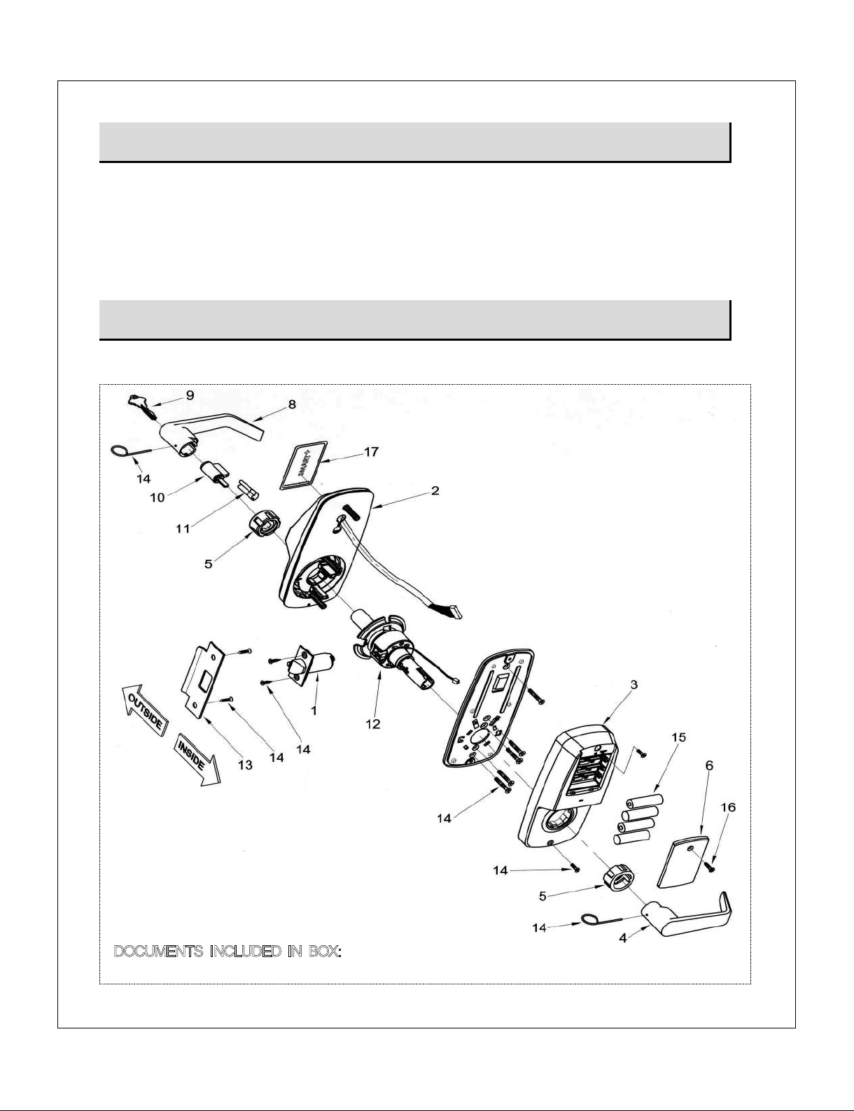
PARTS BREAKDOWN
Confirming the Box Contents The following items should be included in the box:
DOCUMENTS INCLUDED IN BOX:
(Installation Instructions / Programming Instructions / 1 Full Size Template)
- 4 -

Installation and Programming Instructions for Electronic Stand-Alone Cylindrical Locks
- 4 -
Door Prep
§Pencil
§Center punch
§Hammer
§Wood chisel
§Drill with 3/8" or 1/2" chuck
§2-1/8"(54mm) hole saw
§1"(25mm) boring bit
§3/8"(9.5mm) & 7/64"(2.5mm) drill bit
Lock Installation
§#2 phillips screw driver
§Lever removal tool (supplied)
ITEM
NO.
DESCRIPTION
QTY.
1
Latch (2-3/4"(70mm) Backset (Standard))
1
2
Outside Assembly
1
3
Inside Escutcheon
1
4
Inside Lever
1
5
Spacer Bushing
2
6
Battery Cover
1
7
Mounting Plate Assembly
1
8
Outside Lever
1
9
Key (Provided with Cylinder)
2
10
Cylinder
1
11
Cylinder Retainer
2
12
Lock Body
1
13
Strike
1
14
Screw Pack
§(2) 12-24×3/4"(19mm) FL HD Combination Screws for Strike
§(2) 8-32×3/4"(19mm) FL HD Combination Screws for Latch
§(5) 10-32×1-1/5"(30mm) FL HD Machine Screws for Mounting Plate
§(2) M5.0xP0.8-3/4"(19mm) FL HD Machine Screws for Inside Escutcheon
§(1) Lever removal tool
1
15
AA Alkaline Batteries
4
16
Battery Cover Screw
1
17
RF Card
2
PARTS BREAKDOWN (Continued)
TOOLS FOR INSTALLATION
- 5 -- 4 -

Installation and Programming Instructions for Electronic Stand-Alone Cylindrical Locks
- 5 -
INSTALLATION INSTRUCTIONS
Step #1 Verify Hand and Bevel of Door
Stand on outside/locked side of the door when determining the door hand.
Note:
This lock is non-handed and the lever can be flipped around to the desirable hand.
Left Hand
Hinges Left
Open Inward
"LH"
Left Hand
Reverse Bevel
Hinges Left
Open Outward
"LHRB"
Right Hand
Hinges Right
Open Inward
"RH"
Right Hand
Reverse Bevel
Hinges Right
Open Outward
"RHRB"
Step #2 Door & Frame Preparation
IMPORTANT:
The accuracy of the door preparation is critical for the proper functioning
and security of this lever handle lock. Misalignment can cause premature wear and tear
and a lessening of security.
For uncut Doors and Frames
A. Mark Centerline
Draw a horizontal centerline for the lever (the
centerline for the lock body hole) on the edge and
on both sides of the door at the desired height
above the finished floor.
Note 1:
The recommended height from the floor to the
lock is 38"(97cm).
Note 2:
If strike mortice already exist in frame, locate
the horizontal centerline of the lock using strike mortice
as reference.
- 6 -

Installation and Programming Instructions for Electronic Stand-Alone Cylindrical Locks
- 6 -
B.
Position Template and Mark Drill Points
Be
sure to verify backset before marking and drilling
door.
1. Fold and Place template on high edge of door at
the horizontal centerline.
2. Mark centers of holes at proper backset. For
beveled and square edge doors, mark both sides
of the door.
C. Drill Holes and Mortise for Latch face
1. Drill 2-1/8"(54mm) diameter hole through the door.
Cut notches as shown on template.
2. Drill 1"(25mm) diameter hole through the door
according to template.
3. Drill 1"(25mm) diameter hole in edge of door.
Mortise for latch front 5/32"(4mm) deep 1-1/8"
(29mm) wide × 2-1/4"(57mm) high.
4. Drill three (3) 3/8"(9.5mm) diameter holes through
door.
5. Drill the holes for the screws used to install the
latch. 7/64"(2.5mm)
Note:
To avoid splintering wood doors, drill holes from
both sides of the door.
D. Prepare and Install Strike (Wood Frames Only)
1. Mark vertical line and centerline on frame exactly
opposite center of latch hole.
2. Drill two (2) 1"(25mm) holes 5/16"(8mm) above
and below centerline.
3. Mortise a cutout for strike. Use strike as a pattern
for mortise. (Strike should fit flush with frame.)
4. Drill the holes for the screws used to install the
strike. 7/64"(2.5mm)
- 7 -- 6 -
Installation and Programming Instructions for Electronic Stand-Alone Cylindrical Locks
- 7 -
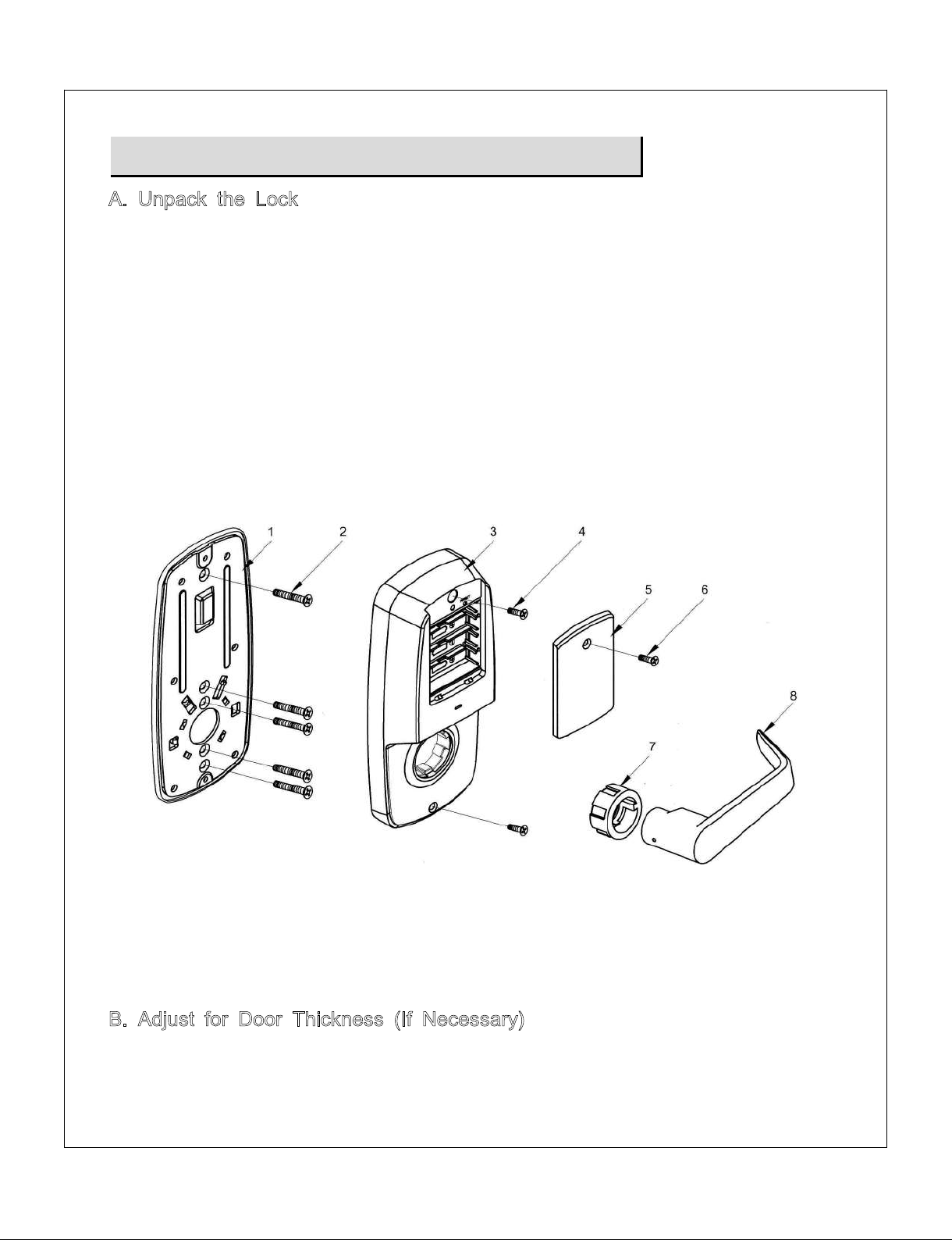
1. Mounting Plate Assembly
2. Mounting Plate Screws
3. Inside Escutcheon
4. Inside Escutcheon Screw
5. Battery Cover
6. Battery Cover Screw
7. Spacer Bushing
8. Inside Lever
Step #3 Prepare Lock for Installation
A. Unpack the Lock
The lock is packed in such a way to represent how it will install on the door.
Before installation:
1. Disassemble the inside escutcheon.
1) Remove the inside lever and spacer bushing with the lever removal tool provided.
2) Separate the mounting plate assembly from the inside escutcheon.
2. Remove the battery cover
1) Unscrew the battery cover screw using the #2 phillips screw driver.
2) Take the battery cover off.
The outside assembly stays assembled.
B. Adjust for Door Thickness (If Necessary)
FLock is factory-assembled for 1-3/4"(45mm) thick doors.
FIt can be adjusted for door thickness range from 1-3/8"(35mm) to 2"(51mm).
- 8 -
Installation and Programming Instructions for Electronic Stand-Alone Cylindrical Locks
- 8 -
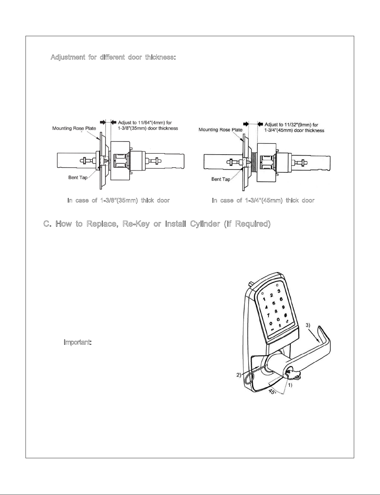
1. Remove outside lever, spacer bushing and outside assembly (See C below).
2. Rotate outside mounting rose plate for proper door thickness as shown below.
3. Position of bent taps as shown below must match (ensure the bent taps are
horizontally crossed).
4. Reassemble outside assembly, spacer bushing and outside lever by reversing
procedures.
In case of 1-3/8"(35mm) thick door
In case of 1-3/4"(45mm) thick door
1. Remove outside lever
1) Insert key, rotate 45° clockwise and hold.
2) Depress lever retainer with lever removal tool
(provided).
3) Slide lever off lock.
2. With outside lever in hand, use standard pliers to pull
out cylinder retainer.
3. Remove key and cylinder from outside lever.
4. Insert new cylinder.
5. Secure by pressing cylinder retainer flush with the
lever.
6. Insert key into cylinder.
Important: Make sure the key-cut side of key lines up
facing towards the end of the lever. If the key is
inserted incorrectly, the lock will reassemble and might
appear to properly work; however, when the key is
removed, the latchbolt will remain retracted.
7. Rotate key 45° counterclockwise.
Push the lever onto the spindle until fully seated.
Pull on lever to insure properly seated.
Adjustment for different door thickness:
C. How to Replace, Re-Key or Install Cylinder (If Required)
- 9 -- 8 -
Installation and Programming Instructions for Electronic Stand-Alone Cylindrical Locks
- 9 -
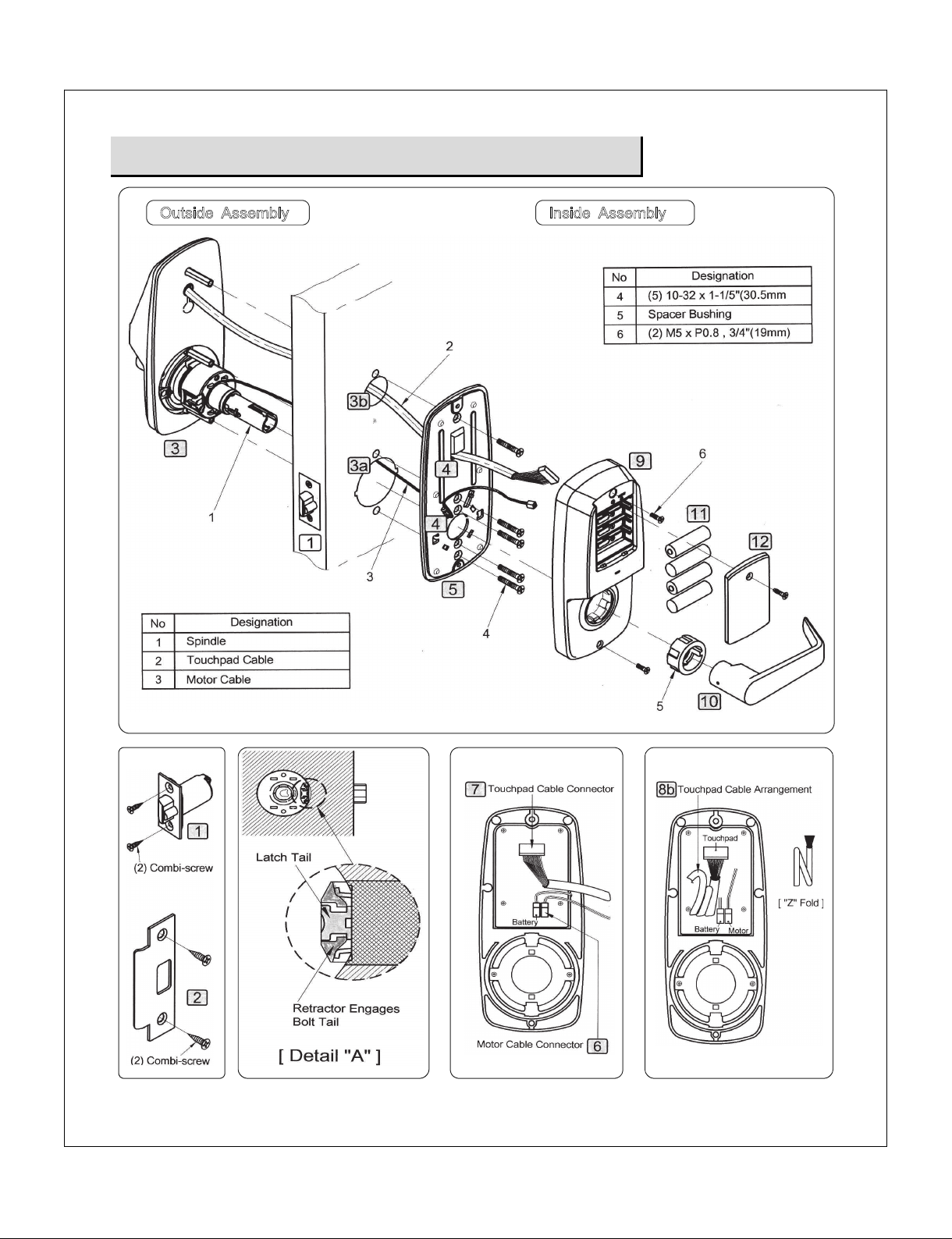
Step #4 Lock Installation
Outside Assembly
Inside Assembly
- 10 -

Installation and Programming Instructions for Electronic Stand-Alone Cylindrical Locks
- 10 -
PROCEDURES
1. Install latch in door. Be sure that bevel edge of bolt faces strike. Attach with two
screws supplied.
2. Install strike on the door frame.
3. Insert outside assembly through door, making sure that the lock body frame hooks
latch case and retractor engages bolt tail(s). DO NOT FORCE (See Detail A above). If
lock body does not engage latch easily, check door preparation for errors.
3a. Guide motor cable (red and black wires) through 2-1/8"(54mm) diameter hole.
3b. Guide touchpad cable through 1"(25mm) diameter upper hole.
4. Guide motor cable and touchpad cable through rectangular holes on mounting plate
assembly (motor cable - below rectangular hole / touchpad cable - above rectangular
hole).
5. Slide mounting plate assembly over outside assembly, lining up top and bottom screw
guides with holes in door. Secure both assemblies with (5) 10-32x2-9/16" (35mm)
mounting plate assembly screws. Do not over-tighten.
6. Attach motor cable connector to the inside escutcheon PC board lower header.
7. Attach the touchpad cable connector to the inside escutcheon PC board header as
illustrated.
8. Slide inside escutcheon over mounting plate assembly.
CAUTION :
8a. Position motor cable against mounting plate assembly. Avoid pinching wires against
spindle and any sharp metal part of the assembly.
8b. “Z” fold touchpad wire cable and lay against the back recessed area of the inside
escutcheon. Position and bend wires to prevent binding when installing the inside
escutcheon over the mounting plate assembly.
9. Install and secure inside escutcheon with the (2) M5xP0.8-3/4"(19mm) screws through
inside escutcheon and into the mounting plate assembly.
10. Slide inside lever onto spindle and push in to attach.
11. Install (4) AA alkaline batteries into controller compartment being careful to align +/-
polarity properly.
12. Install battery cover and tighten screw.
- 11 -- 10 -

Installation and Programming Instructions for Electronic Stand-Alone Cylindrical Locks
- 11 -
Step #5 Test Lock Operation
Test the Operation of the Mechanical Lockset
If you encounter problems while performing any of the following tests, review the
installation instructions and this guide and correct any problems.
CAUTION : DOOR MUST REMAIN OPEN DURING INSTALLATION. USE DOOR STOP.
Mechanical Test
A. Rotate the inside lever. Operation should be smooth, and the latch should retract.
B. Insert the key into keyway and rotate the key to open the door. Operation should be
smooth, and the latch should retract.
Electronic Test
A. To unlock outside lever.
1. Press the [Wake Up] button to illuminate the number pad with beep.
2. Enter factory defaults Master Code [123456] and press the [✱] button.
3. Outside lever will retract the latch
B. In case of use with RF Card - refer to Programming Guide.
HARDWARE TROUBLESHOOTING
Cycle the lock in both the locked and the unlocked positions. If problems are found:
Symptom
Suggested Action
Door is binding
ŸCheck that door and frame are properly aligned and door is
free swinging.
ŸCheck hinges: They should not be loose or have excessive
wear on knuckles.
Latchbolt will not deadlock
ŸEither strike is out of alignment or the gap between the door
and frame is too great.
ŸRealign strike or shim strike out towards flat area of latchbolt.
Latchbolt does not retract or
extend properly
ŸLatchbolt tail and retractor are not properly positioned:
FRemove lockset. Look though 2-1/8" hole and verify
latchbolt tail is centered between top and bottom of hole.
FRemove latchbolt and insert lockset. Look though latchbolt
hole and verify retractor mouth centered in hole. If not,
adjust outside mounting rose plate.
FIf necessary, rebore holes to line up retractor and tail.
- 12 -
Installation and Programming Instructions for Electronic Stand-Alone Cylindrical Locks
- 12 -
PROGRAMMING GUIDE
Take the time to read through this guide to familiarize yourself with the features and oper
ation of the lock, and its quick and easy programming procedures.
TABLE OF CONTENTS
Overview ··················································································································································· 12
Operation of Lock ··························································································································· 13~14
Programming Features ··················································································································· 15~17
Programming ····································································································································· 18~22
Miscellaneous Information ···················································································································· 23
Glossary ···················································································································································· 24
Troubleshooting ······································································································································· 25
User PIN Code Record Sheet ··········································································································· 26
OVERVIEW
User Access Methods
Touchpad Entered User PIN Codes.
RF Card.
Metal Key cylinder.
User Features
1000 users.
User code length from 4-6 digits.
Preparing to Program your Lock
At first glance, your new lock may look complicated, but it is in fact designed in
a very straightforward way. The keypad contains 12 buttons: numbers 1 through
9 plus zero, a star button [✱] and a pound button [#].
These 12 buttons are all you need to program your lock.
All features can be programmed manually through the touchpad.
This guide will show you how to program your lock manually.
The lock can be programmed for Passage mode, Lockout mode settings. Auto
re-lock time and Beep volume are adjustable and can be changed from factory
default.
Stand-Alone Access Control System is a series of State-of-the-Art Microprocessor-Based
programmable Touchpad-Entry and Proximity Security Locks.
- 13 -- 12 -

Installation and Programming Instructions for Electronic Stand-Alone Cylindrical Locks
- 13 -
Opening the door with a RF Card
Press the [Wake Up]
button to illuminate the
number pad with beep.
Place a registered RF Card in front
of the touchpad like above figure.
Turn lever to open door.
Opening the door with a Metal Key
A. Insert the key into keyway.
B. Rotate the key to open the door.
OPERATION OF LOCK
Opening the door with a PIN Code
Press the [Wake Up]
button to illuminate the
number pad with beep.
Enter a registered PIN Code and
press [✱] button.
Turn lever to open door.
- 14 -

Installation and Programming Instructions for Electronic Stand-Alone Cylindrical Locks
- 14 -
Settings
Factory Defaults
Master PIN Code
123456
Lockout Mode
Unprogrammed
Passage Mode
Unprogrammed
Re-lock Time
5 seconds
Wrong Code Entry Limit
5 times
Shut Down Time
60 seconds
Beep Volume
2 levels
Scope of Master, Manager, User Settings
Settings
Master
Manager
User
Entrance Authorization
√
√
√
Register/Change Master PIN Code
√
Register/Delete Manager PIN Code
√
Register/Delete User PIN Code
√
Register/Delete RF Card
√
Registering One-time User PIN Code
√
Setting Up/Releasing User Lockout Mode
√
√
Entrance Authorization at Lockout Mode
√
√
Setting Up/Releasing Passage Mode
√
√
Setting Up the Sound Volume
√
√
Setting Up the Re-lock Time
√
√
Factory Defaults
- 15 -- 14 -

Installation and Programming Instructions for Electronic Stand-Alone Cylindrical Locks
- 15 -
Symbols Description
W
Press the [Wake Up] button on the outside assembly. It is used to start
inputting or to exit the Program mode.
0~9Press the indicated number buttons.
✱
Press the [✱] button. It is used to complete an input process.
#Press the the [#] button. It is used to enter Programming mode.
Mstr PIN Enter the Master PIN Code
Mgr
PIN Enter the Master PIN Code (4~6 digits in length).
UPIN Enter the User PIN Code (4~6 digits in length).
Low Battery Icon. When battery power is low, the low battery icon will begin
blinking.
Passage Mode Icon.
Lockout Mode Icon
Menu and Icons
PROGRAMMING FEATURES
Outside
Inside
- 16 -
(Only 6 digits in length) [Factory Default : 123456]
Installation and Programming Instructions for Electronic Stand-Alone Cylindrical Locks
- 16 -
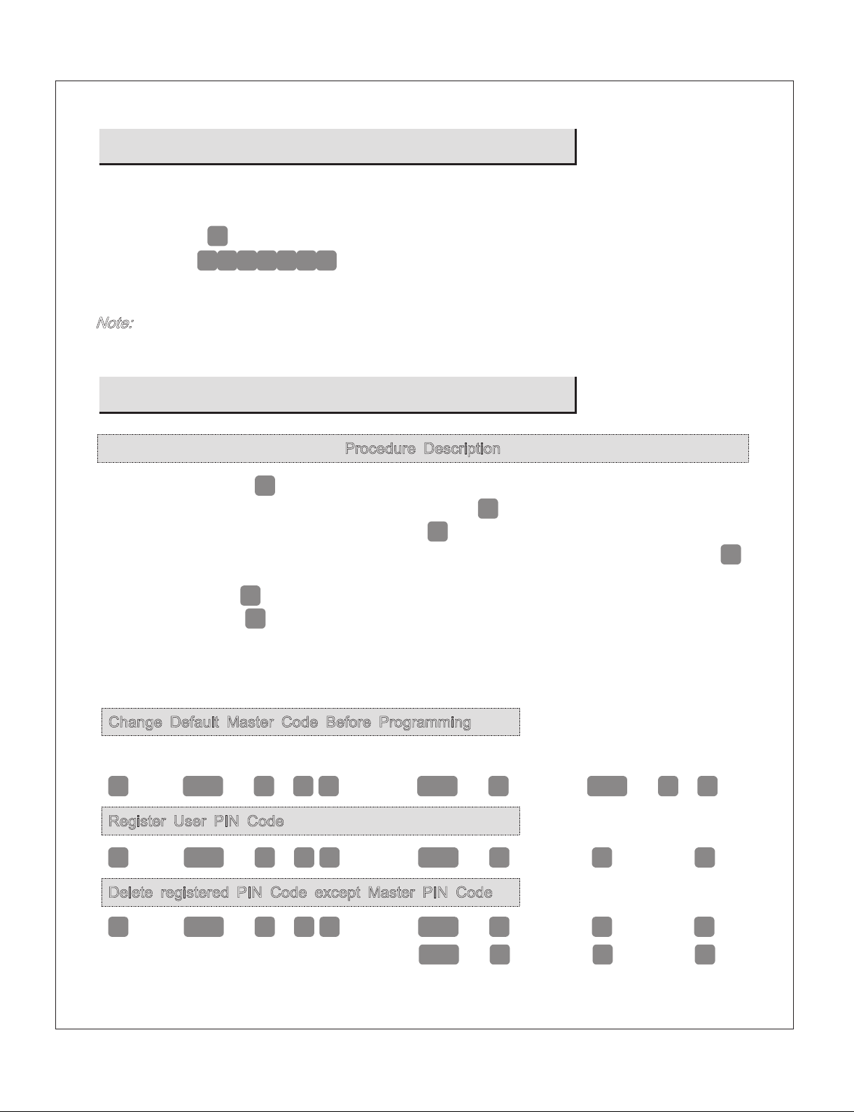
To Begin Programming:
Feature Programming Through Master Code
Change Default Master Code Before Programming
1
w
Default
Mstr
PIN
#
1
#
Enter New
Mstr
PIN
#
Enter New
Mstr
PIN
#
✱
Register User PIN Code
w
Mstr
PIN
#
2
#
Enter
U
PIN
#
#
✱
Delete registered PIN Code except Master PIN Code
w
Mstr
PIN
#
3
#
Registered
U
PIN
#
#
✱
Registered
Mgr
PIN
#
#
✱
Procedure Description
Press the Wake Up
w
button to activate.
Step 1. Enter the Master PIN Code and press the
#
button.
Step 2. Enter Program Code and press the
#
button.
Step 3. Enter digit corresponding to the function to be performed and press the
#
button.
Step 4. Press the
#
button to confirm.
Step 5. Press the
✱
button to complete the process and conclude the Programming
session.
The Lock is preset at the factory with Master PIN Code [123456].
A. Press the
w
button to illuminate the number pad with beep.
B. Entering
1
2
3
4
5
6
✱
will unlock the lock allowing the outside lever to retract
the latchbolt.
Note: The Master Code must be changed (i.e., “Forced Change”) from the factory default
prior to adding users.
- 17 -
(Only 6 digits in length)
2345
Installation and Programming Instructions for Electronic Stand-Alone Cylindrical Locks
- 17 -
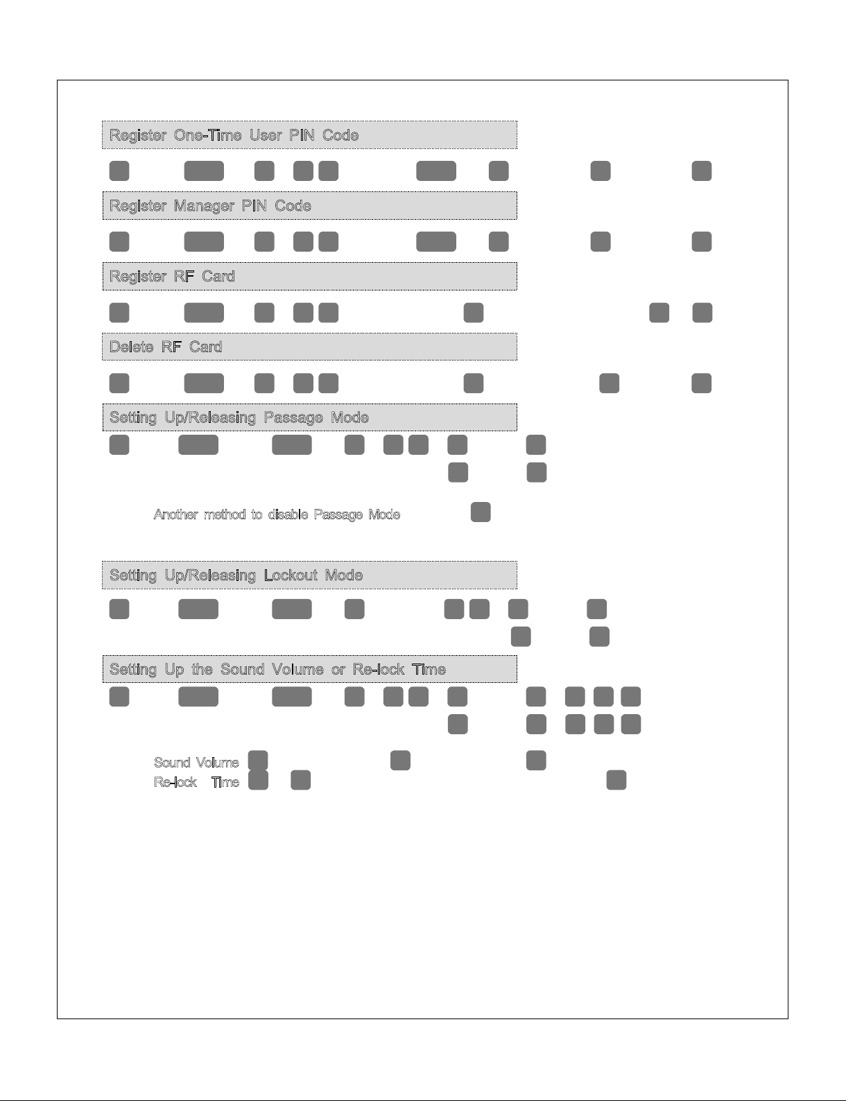
Register One-Time User PIN Code
w
è
Mstr
PIN
#
è
4
#
è
One-Time
U
PIN
#
è
#
è
✱
Register Manager PIN Code
w
è
Mstr
PIN
#
è
6
#
è
Enter
Mgr
PIN
#
è
#
è
✱
Register RF Card
w
è
Mstr
PIN
#
è
8
#
è
Enter the Card
Register No. (1~999)
#
è
Place the RF Card
on Touchpad
#
è
✱
Delete RF Card
w
è
Mstr
PIN
#
è
9
#
è
Enter the Card
Registered No.
#
è
#
è
✱
Setting Up/Releasing Passage Mode
w
è
Mstr
PIN or
Mgr
PIN
#
è
5
#
è
1
Enable
✱
è
3
Disable
✱
FAnother method to disable Passage Mode: Press the
w
button for 3seconds, will disable Passage
Mode.
Setting Up/Releasing Lockout Mode
w
è
Mstr
PIN or
Mgr
PIN
#
è
7
#
è
1
Enable
✱
è
3
Disable
✱
Setting Up the Sound Volume or Re-lock Time
w
è
Mstr
PIN or
Mgr
PIN
#
è
0
#
è
1
Volume
#
è
1
~
4
✱
è
2
Re=lock
Time
#
è
1
~
9
✱
FSound Volume:
1
minimum volume ~
3
maximum volume,
4
mute.
FRe-lock
Time:
1
to
9
seconds through feature settings. (factory default
5
five seconds)
- 18 -

Installation and Programming Instructions for Electronic Stand-Alone Cylindrical Locks
- 18 -
Change Default Master Code Before Programming
Register User PIN Code
w
Default
Mstr
PIN
#
1
#
Enter New
Mstr
PIN
#
Enter New
Mstr
PIN
#
✱
w
Mstr
PIN
#
2
#
Enter
U
PIN
#
#
✱
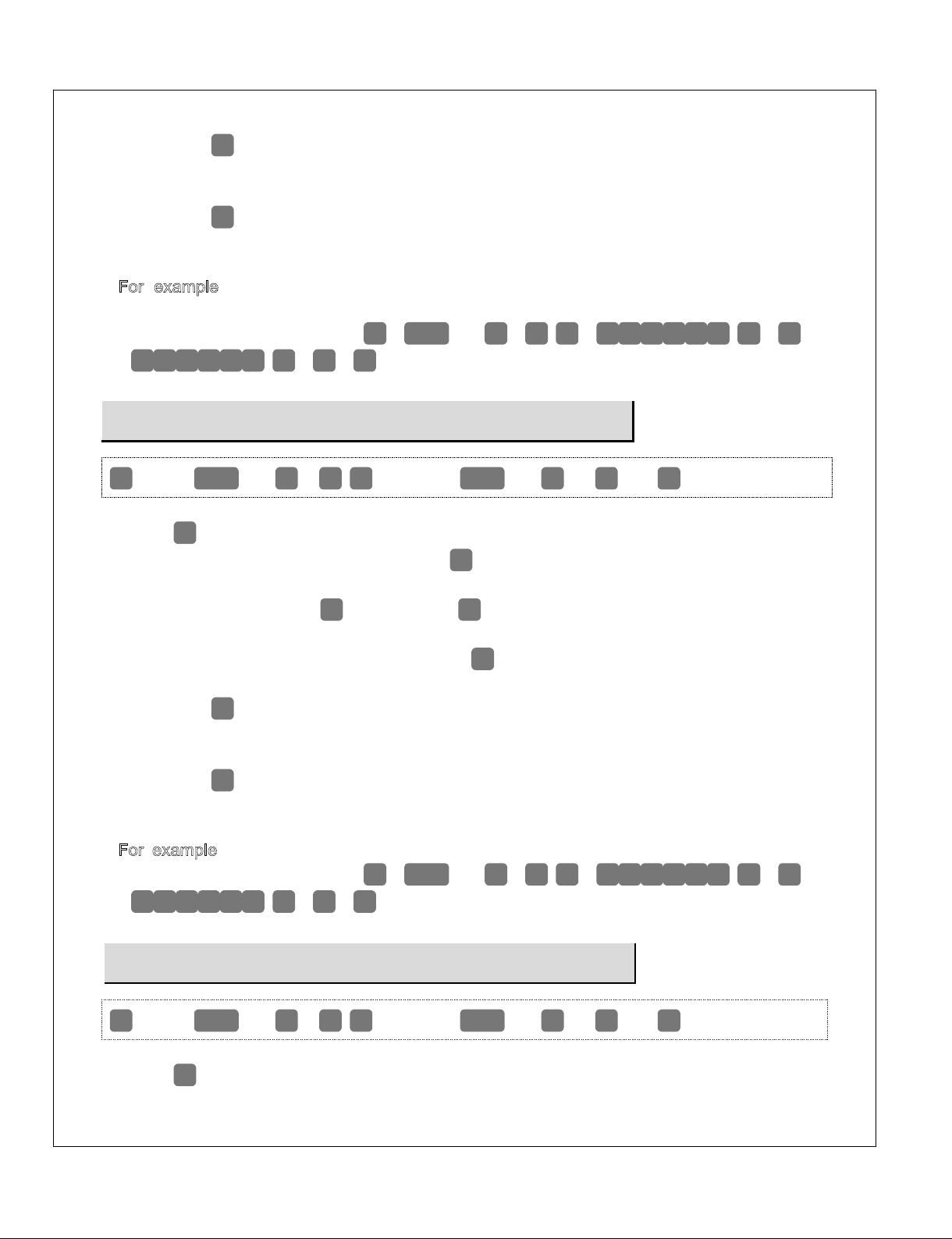
PROGRAMMING
Note: The factory default Master Code must be changed prior to adding users.
Press the
w
button to activate.
1. Enter the default Master PIN Code
1
2
3
4
5
6
and press the
#
button.
Green and Red LED blinks.
2. Enter the Program Code
1
and press the
#
button.
Green and Red LED blinks.
3. Enter the new Master PIN Code and press the
#
button.
Beep melody with Green LED blinks.
4. Enter the new Master PIN Code again and press the
#
button.
Beep melody and Number pad blink one time.
5. Press the
✱
button.
Completes with beep sound.
[For example, if you want your new Master PIN Code to be "258013".
Press:
w
1
2
3
1
3
1
3
4
5
6
#
1
#
2
5
8
0
#
2
5
8
0
#
✱
]
Now that the Master Code has been changed, there is no need to change it again
(unless you want to).
Press the
w
button to activate.
1. Enter the Master PIN Code and press the
#
button.
Green and Red LED blinks.
2. Enter the Program Code
2
and press the
#
button.
Green and Red LED blinks.
3. Enter the new User PIN Code and press the
#
button.
Beep melody with Green LED blinks.
- 19 -
(Only 6 digits in length)
Installation and Programming Instructions for Electronic Stand-Alone Cylindrical Locks
- 19 -
Delete registered PIN Code except Master PIN Code
w
è
Mstr
PIN
#
è
3
#
è
Registered
U
PIN
#
è
#
è
✱
Register One-Time User PIN Code
w
è
Mstr
PIN
#
è
4
#
è
One-Time
U
PIN
#
è
#
è
✱
4. Press the
#
button.
Beep melody and Number pad blink one time.
F [Repeat steps 3 and 4 for each new user (if necessary).]
5. Press the
✱
button.
Completes with beep sound.
[For example, John Smith and Jessica are users. You want to register their User PIN
Codes "111222" and "223344".
Program the lock by pressing:
w
è
Mstr
PIN
#
è
2
#
è
1
1
1
2
2
2
#
è
#
è
2
2
3
3
4
4
#
è
#
è
✱
]
Press the
w
button to activate.
1. Enter the Master PIN Code and press the
#
button.
Green and Red LED blinks.
2. Enter the Program Code
3
and press the
#
button.
Green and Red LED blinks.
3. Enter the registered PIN Code and press the
#
button.
Beep melody with Green LED blinks.
4. Press the
#
button.
Beep melody and Number pad blink one time.
F [Repeat step 3 and 4 for delete of another registered PIN Code (if necessary).]
5. Press the
✱
button again.
Completes with beep sound.
[For example, You want to delete registered PIN Codes "111222” and "223344".
Program the lock by pressing:
w
è
Mstr
PIN
#
è
3
#
è
1
1
1
2
2
2
#
è
#
è
2
2
3
3
4
4
#
è
#
è
✱
]
Press the
w
button to activate.
- 20 -
Table of contents
Popular Door Lock manuals by other brands


Kwikset
Kwikset SMARTCODE 9260CNT-514S quick start guide

danalock
danalock V3 BT HK SCANDI manual

Dometic
Dometic DoorLock DM100 Installation and operating manual

Assa Abloy
Assa Abloy Securitron UnLatch Installation & operating instructions

Signature Hardware
Signature Hardware ULA manual

Dormakaba
Dormakaba UNIQUIN Mounting instructions