08
09
10
11
12
P-03
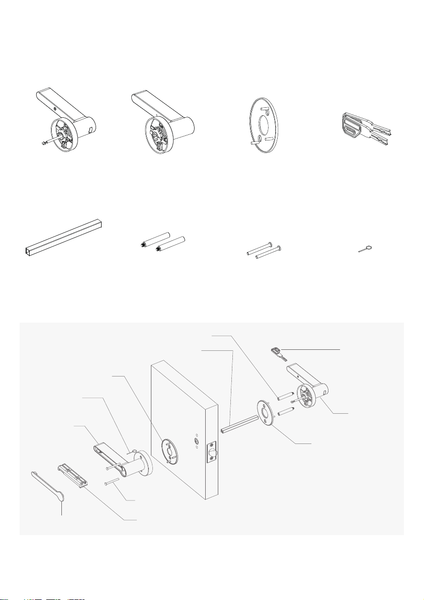
Model A Installation
AExternal handle
EHandle mounting plate
EHandle mounting plate
FKey
GHollow spindle
ISplit bolt
JSelf tapping screw
KSetting needle
B-1 Internal handle cover B-2 Battery cassette
HConnection boss
BInternal handle
CLatch
DStrike plate/cover
05
06
07
Open the door and put something in the doorway to ensure the door doesn't close throughout
installation.
Remove the existing handles. This should be as simple as removing the screws from each handle
and pulling the handles off. You will also need to remove the spindle.
If desired, remove the existing latch in the door and insert the latch provided (C). This may require
some drilling if the latch hole in your door needs to be enlarged. You will also need to remove the
existing strike plate/keep from the door frame, then fit the strike plate (D) provided to your door
frame. This may also require the use of a chisel to ensure it fits correctly. For assistance, or if you
are installing Breeze Model A on a new door, please follow the provided template for fitting
instructions.
If you haven’t already, please make sure the handles open in the correct direction. If they don’t, go
back and follow the ‘Change the handle direction’ instructions to make sure they open correctly
before moving to the next step.
With the external handle (A) in hand, take the connection bosses (H) and screw them into the
positions at the left and right sides of the inside face.
Take the spindle (G) and feed the wire through the hollow opening, then push the spindle into the
handle.
Push the mounting plate (E) over the spindle and connection bosses until its flush with the handle.
Feed the spindle through the latch in the door and the connection bosses through the holes in the
latch. The handle should push flat against the door.
Locate the internal handle (B) and the setting needle (K). At the back of the handle grip, there is a
small hole. Push the setting tool into this hole and press hard until the magnetic handle cover (B-1)
pops off. Remove the cover and also the battery cassette (B-2).
Take the second mounting plate (E) and place it over the spindle.
Holding the internal handle (B), feed the wire and spindle through the spindle hole in the handle.
You will be able to see the cable coming through from the back of the handle.
Push the handle towards the door and locate it into the mounting plate so that it sits flush onto the
door.
01
02
03
04