SOMFY Connected Lock User manual

1
CONNECTED LOCK
Installation and user guide
© 2017 Somfy SAS. All rights reserved - Images for illustration purposes only.
Open me!
2
CONNECTED LOCK
Installation and user guide
© 2017 Somfy SAS. All rights reserved - Images for illustration purposes only.
…
You will soon be able to enjoy
your connected lock!
3
CONNECTED LOCK
Installation and user guide
© 2017 Somfy SAS. All rights reserved - Images for illustration purposes only.
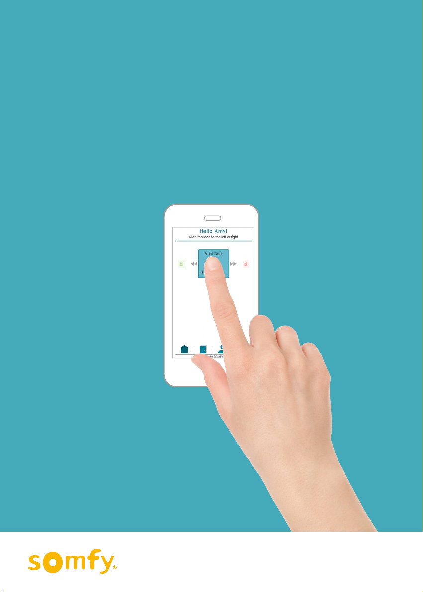
Lock and unlock
your door with
yoursmartphone.
Manage and
controlaccess.
Can be installed easily
on your existing door.
The new way to manage
accesstoyour home!
▶ Hello to peace of mind
You manage all the comings and goings in your home.
▶ Cool access
You choose your access mode: smartphone and/or badges*.
* Accessories sold separately.
▶ Goodbye to hassles
Lock and unlock your door with your smartphone.
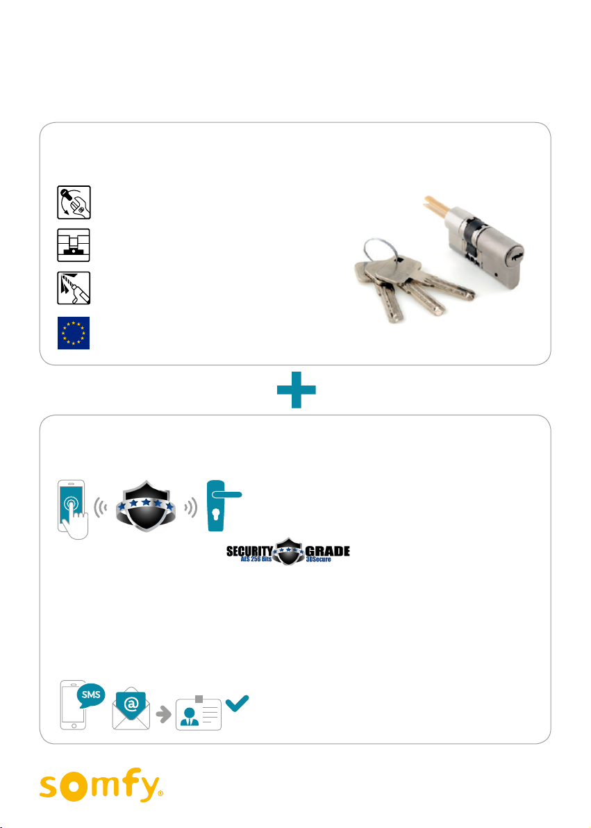
▶ Complete safety
Smartphone login/AES 256 encrypted lock.
Anti-breakage, anti-pull, anti-drill cylinder.
Supplied with secure metal keys.
SOMFY CONNECTED LOCK

4
CONNECTED LOCK
Installation and user guide
© 2017 Somfy SAS. All rights reserved - Images for illustration purposes only.
EASY TO USE
Somfy assists you in installing and using your connected lock.
Our video tutorials give you step-by-step guidance!
They are identified throughout the guide by this icon .
[ Interactive guide ]
You can click the tutorial icon to open the video directly .
1> Introduction: Compatibility of the lock with your doors
2> Installation: Overview
5> Use: Managing users and their access
4> Use: Overview of the interface
3> Use: Quick control
List of video tutorials:

5
CONNECTED LOCK
Installation and user guide
© 2017 Somfy SAS. All rights reserved - Images for illustration purposes only.
Contents
pages
Pack contents 6
INTRODUCTION 7
A. Compatible locks & doors 7
B. Connected lock = Secure 8
C. Access to the connected lock 9
INSTALLATION 10
Installation steps 11
1. CREATE YOUR ACCOUNT 12
2. INSTALL THE CONNECTED LOCK 13
A. Replace the cylinder 16
B. Fix the connected lock 24
C. Start auto-acquisition 27
3. CONFIGURE THE CONNECTED LOCK 30
A. REGISTER THE CONNECTED LOCK 32
B. If you have a badge reader, register it with its cards 33
C. Synchronise the connected lock 34
USE 36
Use case 37
1. CONTROL THE CONNECTED LOCK 38
2. EXPLORE THE CONNECTED LOCK CONTROLLER 44
A. Overview 45
B. Web portal 46
C. Mobile app 49
3. MANAGE THE CONNECTED LOCK 51
A. Manage users and accesses 52
B. Manage products 66
Recap 70
Replacing batteries 71
Troubleshooting 71
Reset 72
Technical data 73
[ Interactive guide ]
You can click each title to access it directly.

6
CONNECTED LOCK
Installation and user guide
© 2017 Somfy SAS. All rights reserved - Images for illustration purposes only.
21 3
4
5 6
8
710
9
11
12
Pack contents Qty
1Metal backing and protection plate ×1
2Connected lock ×1
3Interchangeable covers ×3
4Cylinder kit (with 3 keys and security card) ×1
5Fixing screw for the metal backing plate ×8
6Fixing screw for the connected lock ×3
7 Fixing screw for the cover ×1
8Allen key ×1
9AAA batteries ×4
10 Reversible screwdriver ×1
11 Torx T-10 screwdriver ×1
Pack contents
21 3
4
5 6
8
710
9
11
12
[ Back Contents ]
7
CONNECTED LOCK
Installation and user guide
© 2017 Somfy SAS. All rights reserved - Images for illustration purposes only.
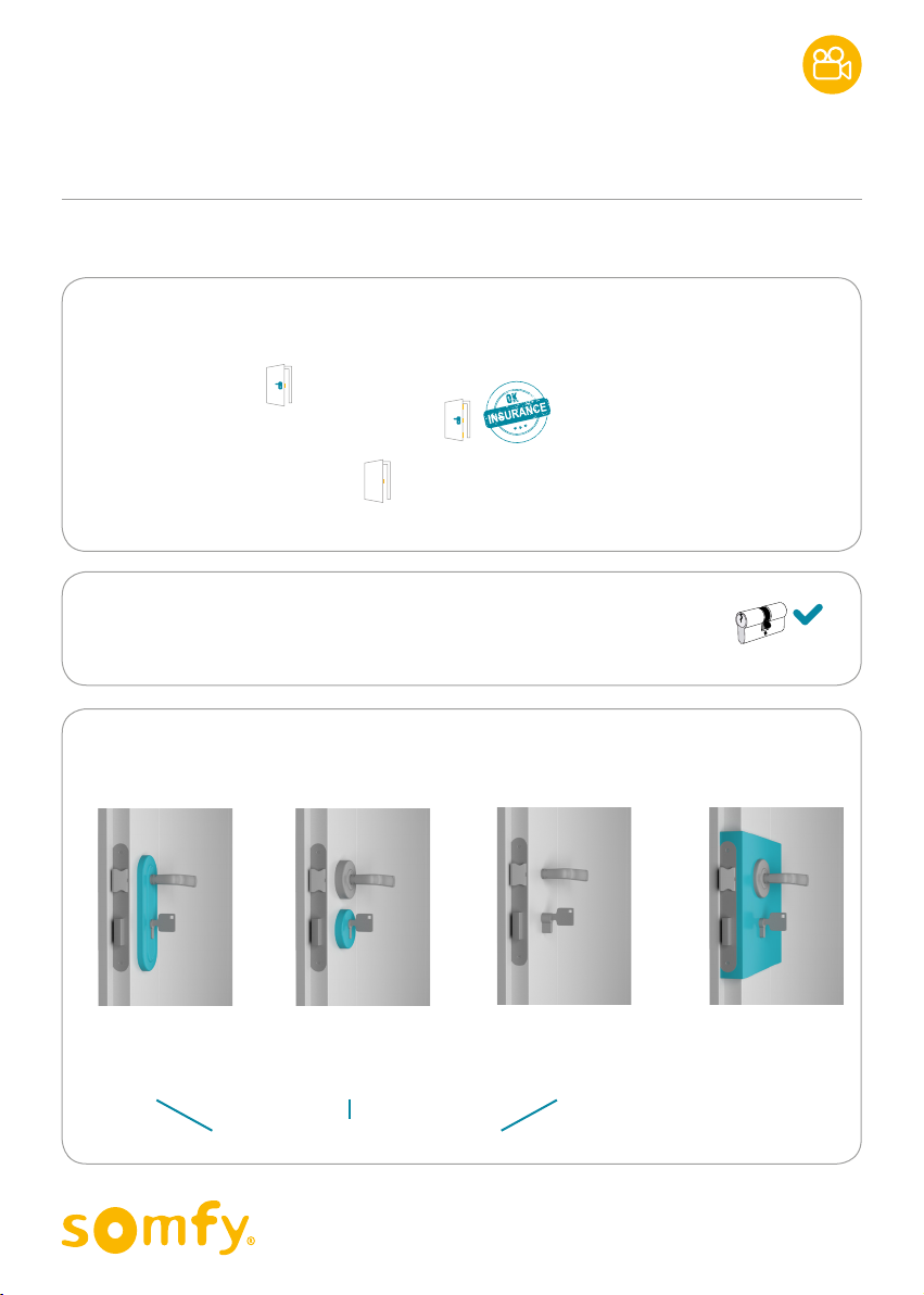
A WIDE COMPATIBILITY…
The connected lock is compatible with:
• Single-point locks
• Multi-point locks required by insurance
(also called “security” locks)
• Doors without handle outside
… AND AN ESSENTIAL ITEM: THE EUROPEAN CYLINDER
Your door is compatible with the connected lock if it has a European cylinder.
IN DETAIL:
The connected lock can be installed on:
Introduction
A. Compatible locks & doors
Lock with escutcheon
Door thickness
+ 2 escutcheons:
Lock with rosette
Door thickness
+ 2 rosettes:
Rim lock
Door thickness without
therim: 3cm max with
standard cylinder; 4,5 cm
max with long cylinder
Bare door
Door thickness:
INTRODUCTION 1
[ Back Contents ]
8 cm max with standard cylinder
9,5 cm max with long cylinder
8
CONNECTED LOCK
Installation and user guide
© 2017 Somfy SAS. All rights reserved - Images for illustration purposes only.
SECURE LOGIN
• Smartphone login/256-bit AES encrypted lock
• Two-factor authentication
Two-factor authentication is a protection provided by Somfy.
- Enhances the security of your account
- 3DSecure system, identical to bank websites
After each login on the web portal, you must confirm your identity by entering
thecodereceived by email or SMS. This protection is enabled by default.
(To disable it, you can go later to My account and untick the relevant box.)
REINFORCED SAFETY LOCK
+ 3 metal safety keys (security card for duplicate included).
• ANTIBREAKAGE
• ANTIPULL
• ANTIDRILL
Meets the requirements of the
European standard EN 1303:2006.
B. Connected lock = Secure
INTRODUCTION
[ Back Contents ]

9
CONNECTED LOCK
Installation and user guide
© 2017 Somfy SAS. All rights reserved - Images for illustration purposes only.
C. Access to the connected lock
Your lock is connected via Bluetooth to a smartphone.
There are 2 ways to access it:
Configure the lock
on the web portal.
Control & manage the lock every
day on your smartphone with
themobile app.
You can also operate the lock manually!
From inside
By turning the knob.
From outside
With one of the keys provided.
INTRODUCTION
[ Back Contents ]


12
CONNECTED LOCK
Installation
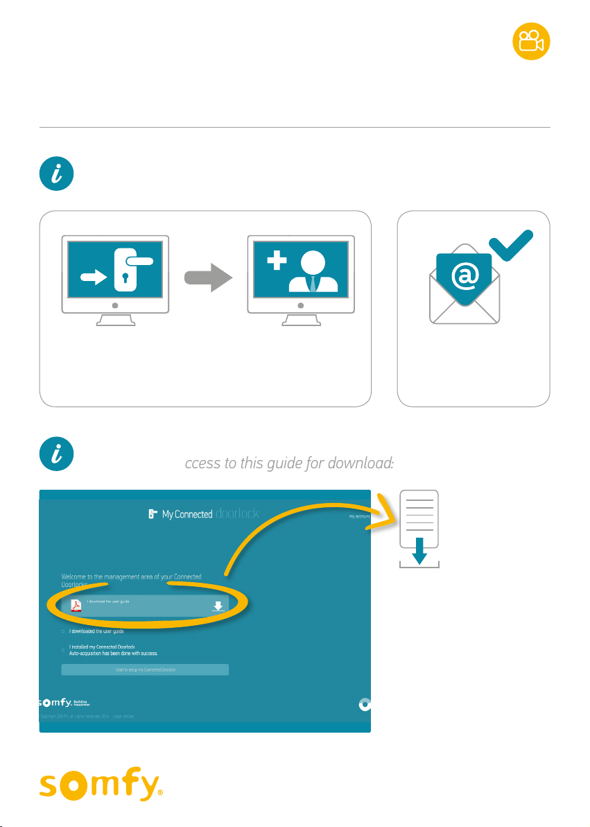
1. CREATE YOUR ACCOUNT
You have already carried out this step to have this guide:
You then have access to this guide for download:
Go to somfy-connect.com
Then select Connected Doorlock
And follow the instructions on the screen.
Confirm the account
via the email
received.
YOU CAN NOW
INSTALL YOUR
CONNECTED
LOCK!
1. CREATE YOUR ACCOUNT 2
© 2017 Somfy SAS. All rights reserved - Images for illustration purposes only. [ Back Contents ]

13
CONNECTED LOCK
Installation
2. INSTALL
THE CONNECTED LOCK
Here is some manual work for you.
Your product is a lock
after all!
Just follow the step-by-step
instructions below.
This step requires work on your door.
Be sure you have enoughtime.
Leave your screen for the moment, you can get back to it later.
2. INSTALL THE CONNECTED LOCK 2
© 2017 Somfy SAS. All rights reserved - Images for illustration purposes only. [ Back Contents ]

14
CONNECTED LOCK
Installation
Simply follow these 3 parts:
A. Replace the
cylinder
B. Fix the
connectedlock
C. Start
auto-acquisition
Checking the door
Before installing your connected lock, please check that your lock
andyour door are operating properly.
• Check that nothing is preventing or stopping the movements of your door.
You should not need force to open or close it.
• With your door closed, check that you can lock and unlock it from inside and outside.
If not, you need to adjust your current lock or your door before installing
yourconnected lock.
2. INSTALL THE CONNECTED LOCK 2
© 2017 Somfy SAS. All rights reserved - Images for illustration purposes only. [ Back Contents ]

15
CONNECTED LOCK
Installation
EXPERT AREA
To help you better understand the rest of the explanations.
How does it work in a few words…
To operate a lock, you must introduce a key into the cylinder:
- the cylinder turns to actuate the bolt
- the bolt locks into the strike plate to close and lock the door.
Quick glossary
Door LOCK CYLINDER
Leaf Moving part of the door.
Frame Fixed part of the door, on which the leaf closes
Strike plate Metal part attached to the frame of a door into which the lock
bolt is engaged to hold the closed leaf.
Bolt Mobile part of the lock that is engaged in the strike plate.
- Latch-bolt Bevelled in shape, it does not necessarily require a key.
- Deadbolt Actuated by a key to lock the lock.
Cylinder Component of the lock that allows it to be locked or unlocked
(alsocalled barrel).
Casement bolt Part of the cylinder actuated by the key, which by turning will
drive the bolt, and thus lock or unlock the door.
2. INSTALL THE CONNECTED LOCK
Leaf Frame Latch-bolt
Deadbolt
Casement bolt
Cylinder
+key
Strike plate
Handle
© 2017 Somfy SAS. All rights reserved - Images for illustration purposes only. [ Back Contents ]
16
CONNECTED LOCK
Installation
Your connected lock has a new cylinder (adjustable)
whichreplaces the one currently installed in the door.
To do this:
A1. Remove the existing cylinder.
A2. Adjust the new cylinder (if necessary).
A3. Put the new cylinder in place.
A. Replace the cylinder
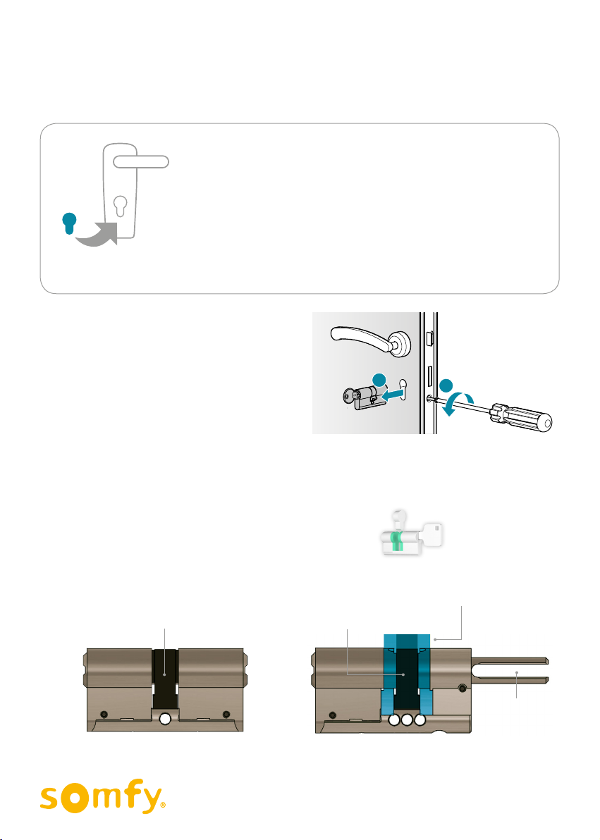
A1. Remove the existing cylinder
Insert your key into the existing cylinder
and then remove the screw (1).
Set it aside as you will need it later.
Then remove the cylinder (2).
A2. Adjust the new cylinder
(ifnecessary)
The aim is to:
• Compare the two cylinders
• If necessary: adjust the new cylinder so that
itmatches your lock and the widthofyour door.
21
Existing cylinder
Original casement bolt (P1) New casement bolt (P1)
2 additional removable parts: P2 and P3
To adjust the position of the main casement bolt
New cylinder
P2 P1 P3
P1
Fork to be
inserted into the
connected lock.
Also releases the
removable parts.
2. INSTALL THE CONNECTED LOCK / A. Replace the cylinder
© 2017 Somfy SAS. All rights reserved - Images for illustration purposes only. [ Back Contents ]
17
Precise measurement of the distance between the centre of the casement bolt
ofthe existing cylinder and the outer end (which goes outside).
Existing
cylinder
Compare the two cylinders
Or:
2. INSTALL THE CONNECTED LOCK / A. Replace the cylinder
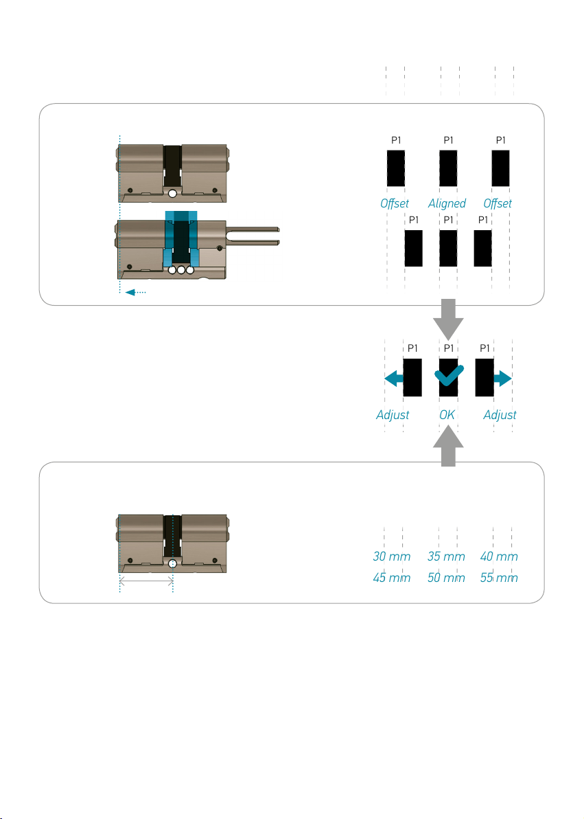
Quick comparison of the position of the casement bolt in both the cylinders.
Existing
cylinder
New
cylinder
P2 P1 P3
Align with the outer end (which goes outside) .
Casement bolts:
Distance:
P1 P1
P1P1 P1
P1
P1P1 P1
Offset Aligned Offset
Adjust OK Adjust
30 mm 35 mm 40 mm
CASE 1 CASE 2 CASE 3
45 mm 50 mm 55 mm
P1 P1
P1P1 P1
P1
P1P1 P1
Offset Aligned Offset
Adjust OK Adjust
30 mm 35 mm 40 mm
CASE 1 CASE 2 CASE 3
45 mm 50 mm 55 mm
P1 P1
P1P1 P1
P1
P1P1 P1
Offset Aligned Offset
Adjust OK Adjust
30 mm 35 mm 40 mm
CASE 1 CASE 2 CASE 3
45 mm 50 mm 55 mm
P1 P1
P1P1 P1
P1
P1P1 P1
Offset Aligned Offset
Adjust OK Adjust
30 mm 35 mm 40 mm
CASE 1 CASE 2 CASE 3
45 mm 50 mm 55 mm
D = xx mm
© 2016 Somfy SAS. All rights reserved - Images for illustration purposes only. [ Back Contents ]
Standard cylinder
Long cylinder

18
CONNECTED LOCK
Installation
ADJUST YOUR CYLINDER
You will have to modify the order of the parts P1 / P2 / P3
to reposition P1 in the right place.
Go directly
to page 24.
CASE 1 ICASE 2 ICASE 3
P1 P1
P1P1 P1
P1
P1P1 P1
Offset Aligned Offset
Adjust OK Adjust
30 mm 35 mm 40 mm
CASE 1 CASE 2 CASE 3
45 mm 50 mm 55 mm
P2 P1 P3 P2 P1 P3
P2
P1
P2
P2
P1
P2
P1
P3
P3
P3
P3
P1
See next page →
2. INSTALL THE CONNECTED LOCK / A. Replace the cylinder
© 2017 Somfy SAS. All rights reserved - Images for illustration purposes only. [ Back Contents ]
Distance:
30mm (standard cylinder)
45mm (long cylinder)
Distance:
40mm (standard cylinder)
55mm (long cylinder)
19
CONNECTED LOCK
Installation
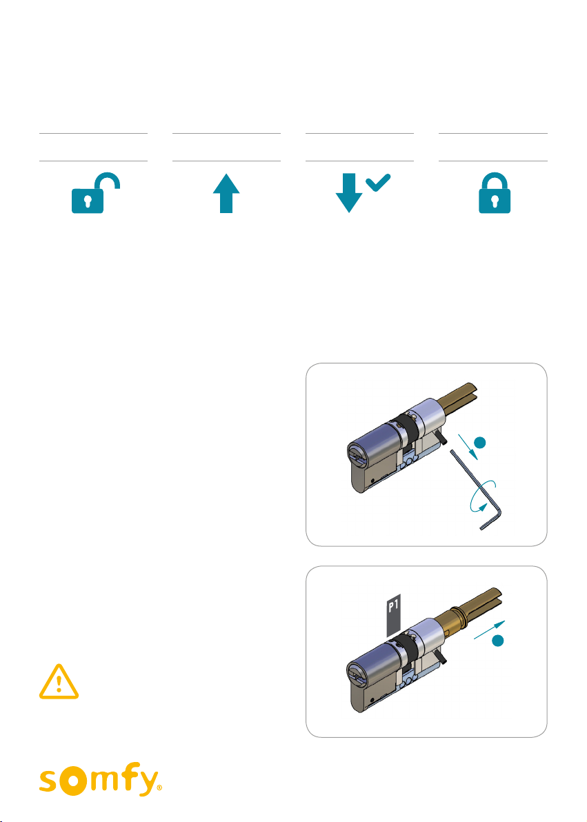
If necessary:
Adjust the new cylinder to make it match with your lock.
>STEP 1
Unlock the removable system.
STEP 1
Unlock
the removable
system.
STEP 2
Remove
the removable
parts and the
casementbolt.
STEP 3
Put the
components back
in the right order.
STEP 4
Relock
the system.
Using the Allen key supplied with
thecylinder, unscrew the pin (1) on
therightend of the cylinder.
Now pull the golden metal fork (2)
torelease the black casement bolt P1.
1
2
Do not remove the fork completely;
simplyslide it.
2. INSTALL THE CONNECTED LOCK / A. Replace the cylinder
© 2017 Somfy SAS. All rights reserved - Images for illustration purposes only. [ Back Contents ]
Table of contents
Other SOMFY Door Lock manuals


Popular Door Lock manuals by other brands


Lockly
Lockly LATCH EDITION SECURE PGD628 installation guide

Salto
Salto XS4 Original+ Ei6 Series installation guide

Signature Hardware
Signature Hardware ELLIS 915879-KE Hardware installation

Spectrum Brands
Spectrum Brands Kwikset Passage installation guide

Schlage
Schlage AD-300 instructions

SAFE TRON
SAFE TRON ML 128 manual


