CrustBuster 850 User manual
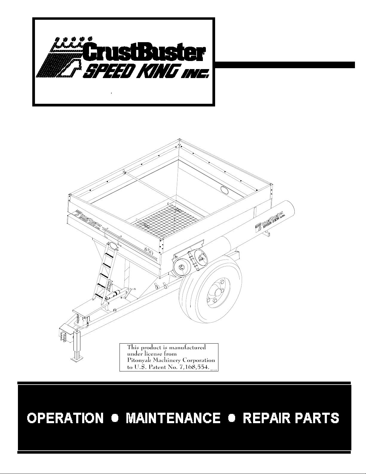
Grain Cart
850 Bu
OWNER'S
MANUAL
#607812 (2007.5)

Table of Contents
Warranty Information . . . . . . . . . . . . . Below
Dealer Check List . . . . . . . . . . . . . . . . . . . . 1
Introduction.........................2
Safety ........................... 3-6
Electrical ...........................7
Dimensions .........................7
Auger .......................... 8-12
Drive System . . . . . . . . . . . . . . . . . . . . 12-16
Hopper ........................... 17
Frame and Axle . . . . . . . . . . . . . . . . . . 18-19
Hydraulics ...................... 20-21
RepairParts ....................... 22
Engineering Specifications . . . . . . . . . . . . 23
Warranty
CrustBuster/Speed King, Inc. of Dodge City, Kansas, warrants consumer products, so far as
the same is of our own manufacture, against defects in material and workmanship under
normal and reasonable use for a period of one (1) year after date of delivery to the original
purchaser. Our obligation under this warranty is limited, however, to furnishing a replacement
part for a defective part, or at our option to repair the defective parts without charge, either
method F.O.B. our works, provided the consumer gives CrustBuster/Speed King,Inc. written
notice within ten (10) days after said part appears to be defective and affords
CrustBuster/Speed King,Inc. an opportunity to inspect. Unless otherwise expressly agreed
to by CrustBuster/Speed King,Inc., the consumer shall bear the expense of installation.
CrustBuster/Speed King, Inc. will not be liable for consequential damages where the loss is
commercial, including but not limited to loss of profit, delays or expenses.
This warranty sets forth the extent of our liability. The foregoing is in lieu of all other
warranties, expressed or implied,including anywarranties that extend beyond the description
of the product.

1
Dealer Preparation Check List
Complete the items below before delivering the cart.
Gearbox filled with oil
All fittings lubricated
All shields in place and in good condition
All fasteners torqued to specifications on chart
Tires inflated to proper pressure according to chart
Remove clevis attachment from hitch before field operation
Check jack stand for proper stability
All decals in place and readable
Operator’s manual has been delivered to owner and the owner has been
instructed on safe and proper use of the cart
Dealer’s Signature
Customer’s Signature
This check list is to remain in the owner’s manual
It is the responsibility of the dealer to complete the procedures listed above before the delivery of this
cart to the new owner.

2
To the Owner
This operator’s manual is to be kept with this cart regardless of ownership.
CAUTION:
Some of the illustrations in this manual may show the shields
or covers removed for clarity. NEVER OPERATE GRAIN CART
without all shields and covers in place.
Be sure to read all instructions for adjusting and operation of the cart contained in this manual. Check
each item referred to and acquaint yourself with them.
After each season, thoroughly clean your cart and inspect it for worn or damaged parts. Leave the
clean-out door located at the bottom open. This allows water to drain.
Your dealer has original equipment parts for your grain cart. When you need parts, always specify the
model number and the serial number. Write these numbers in the spaces provided below. The serial
plate is on the front of the cart.
Model Number Serial Number
850
Introduction
This manual provides the necessary instructions for using and maintaining your grain cart. In addition,
it contains information on service, warranty, parts ordering, and safety considerations when using the
grain cart.
Your grain cart represents the latest in farm equipment technology. It has been continually
redeveloped and improved over the last sixty years to better serve grain farmers all over the country.
Your grain cart is designed to be used with all types of grains without any modification required on the
cart. Grains most commonly used in the cart are wheat, corn, rice, and soybeans.
Your grain cart is designed to be towed by a tractor. The size of the tractor required depends on the
capacity of the cart and the field conditions. The tractor must be equipped with a PTO for the PTO
model on your cart. The tractor also must have an adequate hydraulic system. Two remote hydraulic
connections are required for the PTO models and four remotes for the hydraulic drive models at (2500
psi & 22 gpm).
Please take the time to read this manual, especially the section on safety. If after reading the manual
you have any questions that your dealer cannot answer, please feel free to contact:
CrustBuster/Speed King, Inc.
P.O. Box 1438
Dodge City, Kansas 67801
Phone: 620 227-7106

3
Initial Use
A careful operator is the best insurance against an accident!
CAUTION:
Misuse or modification of this machine can cause
Mechanical breakdown
Personal injury or death
Before using this equipment for the first time, make sure you thoroughly
understand all of the operating instructions and have completely read this
manual.
All carts are shipped field ready; however, before initial use the following items should be checked:
All wheel lug nuts should be torqued to 450 ft-lbs of torque prior to initial use and should be
checked periodically.
Tires should be inflated to 26 psi.
Any retaining straps should be removed from the top auger.
Close dump door on bottom auger tube. (Leave this door open when not in use to allow for
water drainage.)
Make sure sufficient counter weights are used on tractor front end.
Move tractor draw bar to shortest position. Make sure the PTO shaft can telescope both inward
and outward at least 3".
Hitch cart to your tractor. The hitch used on the 850 cart requires a clevis type drawbar. If your
tractor is not equipped with such, please contact your dealer. DO NOT USE clevis attachment
for field use or when cart is loaded. It is for transporting empty cart only.
Connect hydraulic hoses and PTO shaft if equipped. Make sure the PTO shaft can telescope
both inward and outward at least 3".
Test grain door inside cart to ensure smooth operation and proper functioning of indicator.
Look into cart and make sure that the grain door hoses have not been damaged in shipment
and that they are not leaking.
CAUTION:
Before testing the auger make sure no one is near the auger
assembly.
Fold the top auger to full upright position and engage the auger drive, slowly turning the auger.
If auger turns freely, then slowly increase the RPM to proper operating speed. DO NOT
EXCEED 1000 RPM on PTO. Disengage the auger drive, stopping rotation of the auger. Then
slowly return the auger to the transport position. If the auger seems to fold too fast, the flow
control valve must be adjusted to match your tractor’s hydraulic system (see details in auger
section).

4
Operator’s Responsibility
CAUTION:
Operator’s Responsibility:
Most accidents are caused because of neglect or
carelessness. Avoid needless accidents by following all
of the safety precautions listed below.
The user is responsible for inspecting the cart before each use and for having necessary repairs done
to prevent further damage to the cart or possible safety hazards.
It is the responsibility of the user to read the owner’s manual and understand the safe and correct
operating procedures for the owner’s cart.
The operator of this cart must read and understand the material contained in this manual.
The cart should be operated by those responsible and authorized by the owner to do so.
Only a qualified operator should be permitted on the tractor when cart is in operation. No riders
should be allowed on the cart.
Make certain everyone is clear before folding or unfolding the auger.
Never allow anyone inside the hopper for any reason while tractor is running or when hopper
contains grain.
The tongue jack is designed to support an unloaded cart. DO NOT use jack to support a
loaded cart. When jacking up a cart, use caution to make sure all wheels are blocked.
Inspection of the jack and related parts should be done frequently to detect any possible
damages that could cause the jack or related parts to fail. The main cause of jack failure is the
operator moving the cart with the jack still down. If this happens the jack may be unsafe to use.
Replace or repair as needed. It is the owner/operator’s responsibility to ensure the jack and
related parts are in a safe working order.
Do not transport cart on a public road unless the auger is in the transport position (folded back
into the saddle). Also, ensure that the slow moving vehicle decal is in place during daylight and
with approved warning lights at night and other periods of poor visibility.
Carefully maintain control of the grain cart when traveling on roads. Avoid speeds over 8 MPH
when loaded.
Stop the tractor engine before doing any maintenance or repairs to the cart.
Use caution when working with the hydraulic system. Hydraulic fluid can be under extreme
pressure and can cause infection or other serious personal injury.
Make sure all guards are kept in place.
Avoid using near electrical lines with the auger extended. Serious injury or death can result
from contact with electrical lines. USE EXTREME CARE!
Make sure your tractor front end is adequately counter weighted.
Use caution when crossing ditches, levees, etc., or when using on uneven terrain.
Never allow anyone to play inside or around the grain cart. GRAIN CAN SUFFOCATE!

5
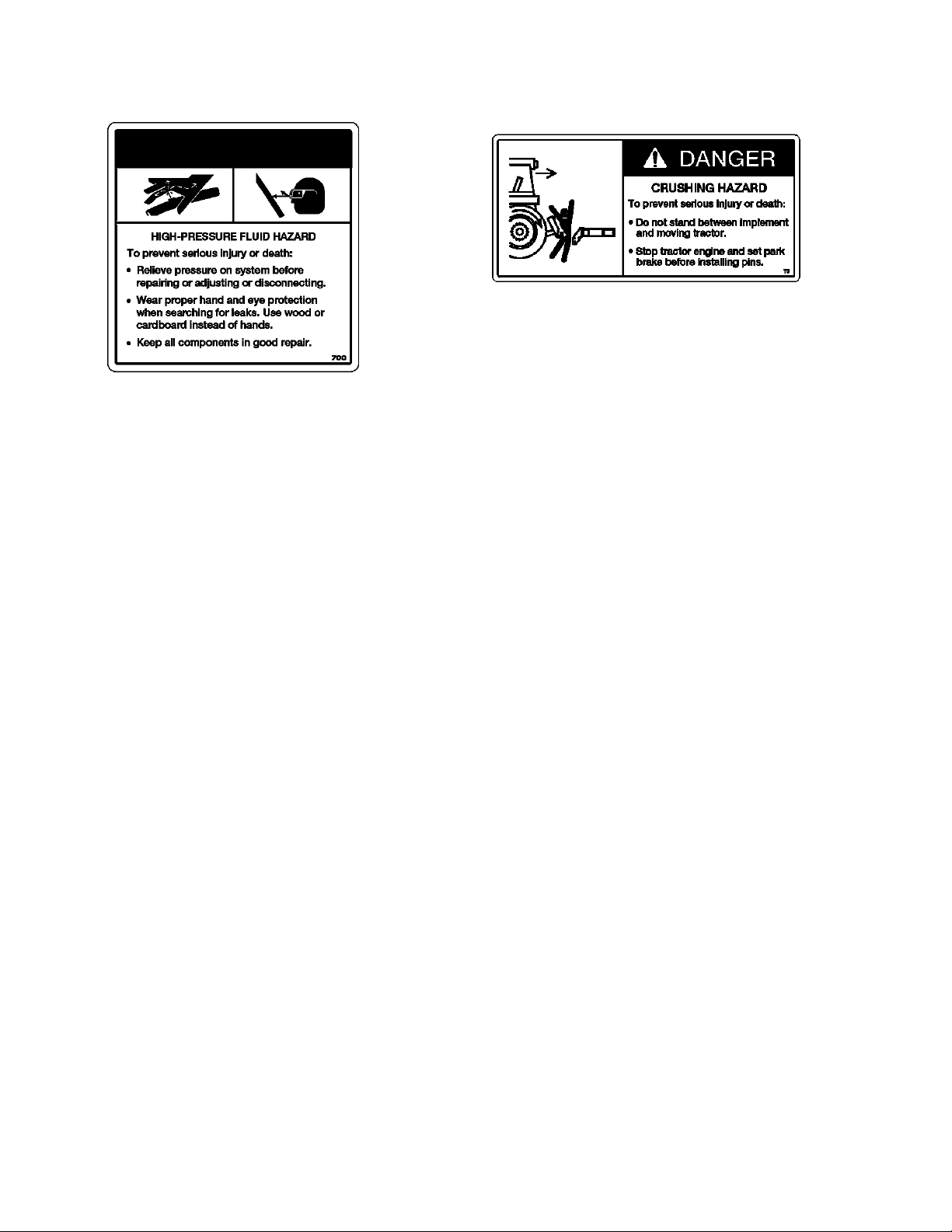
Safety Decals
REMEMBER: If Safety signs have been damaged, removed, become illegible or parts
replaced without decals, new decals must be applied. New decals are available
from your authorized distributor or factory. Individual decals shown below.
#02741700 #604512
#607291
#05327200
#607986
#05328000
#05374400 #608000
6
Safety Decals
#608018 #608026
Operating Instructions
NEVER allow anyone to ride or play on the grain cart.
NEVER enter the grain cart with the PTO or hydraulic motor running or when it contains grain.
Make sure all guards are in place.
Daily grease auger hinge pin, u-joints, and over running coupler.
The grain flow control door (inside slide door) and the clean out door should both be closed
when loading the cart or transporting the cart when filled with grain.
Extending the auger- Use care when folding and unfolding the auger. Make sure no one is
close to the auger. DO NOT extend auger when close to any electrical lines. DO NOT try to
extend or fold the auger while it is running.
If equipped with a PTO drive, slowly engage the PTO at a low RPM, and then slowly increase
to desired tractor RPM. Do not exceed 1000 RPM on PTO.
If equipped with a hydraulic drive, set tractor RPM to 1700 RPM. Snap open hydraulic valve
in tractor. DO NOT slowly open valve. After auger is turning, increase tractor to approximately
2200 RPM.
Slowly open grain flow door after auger is up to speed. Door fully open allows maximum flow.
Use “Clean Out” setting to empty all the grain from the cart.
Use the door to slow grain flow if necessary. DO NOT run auger at slow speed. DO NOT start
auger with the grain flow door open.
Unload the cart.
DO NOT disengage the auger while unloading without first closing the grain flow door.
It is advisable to return the tractor to idle before disengaging the auger.
If you must return to the field or otherwise halt the unloading with a partial load of grain, then
close the grain flow door and let the auger finish emptying the grain left in the auger tubing.
DO NOT return with a partial load and the grain flow door open.
It is recommended to transport the grain cart in the field with auger in the folded position, then
extend when unloading the cart.
7
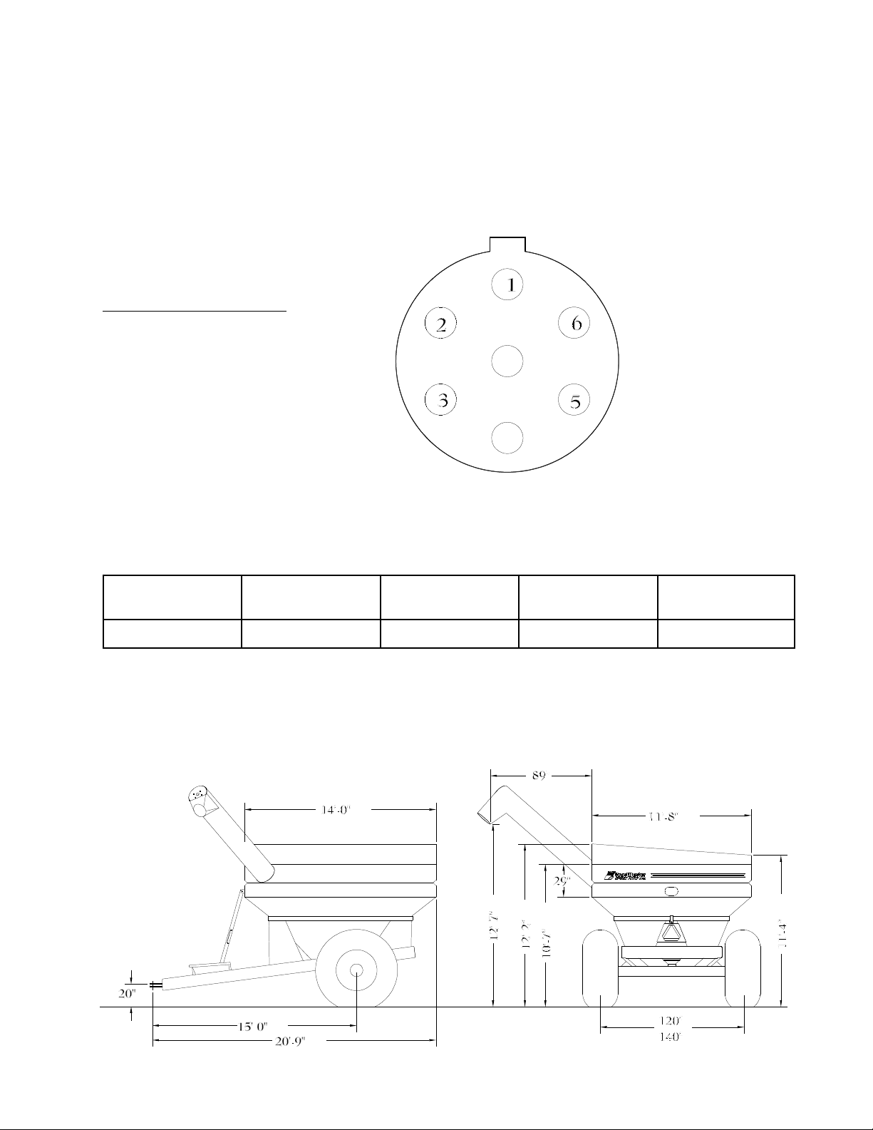
Electrical
Your cart is equipped with a factory installed lighting kit, which includes two tail lights and two work
lights for the auger discharge.
A single switch is provided to control the two work lights.
The connector provided should fit all modern tractors. It is a SAE JS60A seven-point socket. The
schematic below shows the color-coded wiring diagram for this connector.
#607671 - Wiring Harness
1 White - Ground
2 Black - Work Lights
3 Yellow - Left Tail Light
5 Green - Right Tail Light
6 Brown - Amber Flashing
Dimensions
Model # Approx.
Capacity Spindle Size Empty
Weight Tongue
Weight
850 850 Bu 4.5 8720 10%
Specifications and design features are subject to change without notice.

8
Auger System
General
The 850 grain cart consists of a 17" diameter RH auger flighting mounted on a 5" tube. The auger
housing is an 18" diameter tube. All carts employ a hydraulic folding auger. Therefore, each cart
has a bottom auger and a top auger. The auger is driven by either a PTO or hydraulic motor and
can easily be interchanged.
Auger & Tube Assembly for 850 Cart
Item Qty Part No. Description
1 1 875252 Top Auger Assembly
2 1 969550 Auger Hinge Pin
3 1 969543 Fold Lug Pin
4 2 227728 Pin Washer
5 2 330142 Lock Washer ½"
6 2 01029800 HHCS ½" x 1"
7 1 969568 Fold Lug
8 1 330100 HHCS ½” x 4½"
9 1 336644 HHCS ½" x 2 1/4"
Flighting Wear
Auger flighting wears with use and will need replacing. The auger flighting when new is 5 3/4" wide
(18" system). When the flighting has worn ½", it needs repairing. The augers will wear more at the
feed end (bottom end). Therefore, it usually is necessary to replace only 2 feet of flighting on the
feed ends of the augers the first time they are repaired. When they wear the second time, the
whole auger will normally need re-flighting. The augers are balanced at the factory and MUST be
balanced by a qualified technician when re-flighted. Failure to do so can cause bearing damage
and unsatisfactory operation.
Auger Removal
To remove either auger, the top auger must be in the transport position (resting in the transport
saddle). The bottom auger is removed by first unbolting the hanger bearing, then sliding the auger
upward and out of the housing tube. The bottom auger is NOT attached in any way and should
easily lift out of the cart. To remove the top auger, first remove the bolt in the center of the top
shaft. Remove the retaining washer on the top of the auger. The top auger should then slide
downward and out of the housing tube. The cart is equipped with a single top auger spring for
correct engaging pressure.
Auger Installation
All augers must be in the transport position with the top auger resting in the transport saddle in
order to be installed.
9
Auger System
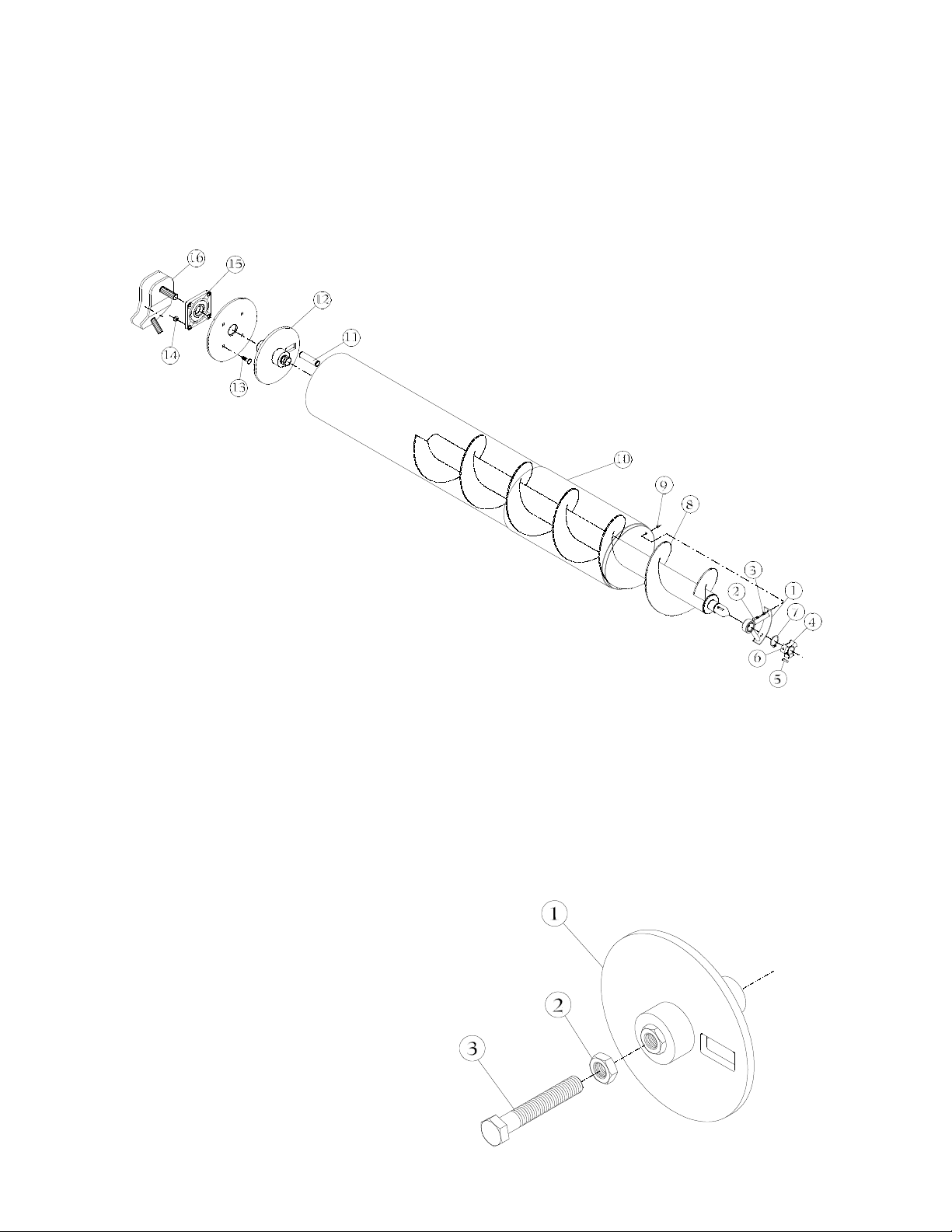
Bottom Auger
The bottom auger is replaced by sliding the auger downward through the housing tube. The auger
may need to be turned to align the bottom drive pin with the matching holes in bottom drive plate.
Make sure the bottom drive pin is completely engaged in bottom drive plate. Replace the hanger
bearing. Make sure it is reinstalled as it was originally and that it does not bind on the auger pilot
shaft. There should be approximately 1/8" clearance between the bearing and the pilot shaft.
NOTE: It is NOT necessary to remove the bottom drive plate to remove the bottom auger.
Item Qty Part No. Description
1 1 640102 Hanger Bearing
2 2 01147800 HHCS ½" x 1½"
3 2 330159 Flat Washer ½"
4 1 607457 Drive Collar
5 2 311670 Key ½" x 1 3/4”
6 2 337998 Screw 3/8" x 1" Socket Hd
7 1 337840 Snap Ring 2½" External
8 1 968081 Bottom Flighting
607861 Flighting Only
Item Qty Part No. Description
9 2 330134 Hex Nut ½"
10 1 640847 Bottom Auger Weldment
11 1 311647 Bottom Drive Pin
12 1 873554 Bottom Drive Plate
Assembly
13 4 336164 Carriage Bolt 5/8" x 2½"
14 4 01572700 Nylock Hex Nut 5/8"
15 1 403519 Bearing 2 1/4" 4B Flange
16 1 472407 Gearbox 50 Degree 1:6:1
Bottom Drive Plate
The bottom drive plate installs on the gearbox output shaft by means of a special splined bushing
that is welded to the plate. It rests on the bottom bearing so the weight of the auger does not rest
on the gearbox itself. There should be approximately 1/4" space between the bottom drive plate
and the boot plate on the bottom of the auger housing.
The drive plate must be removed to change seals on the gearbox or do other repairs to the
gearbox. To remove the bottom drive plate, first raise the bottom auger off the drive plate. There
is a stainless steel bolt located on top of the drive plate bushing. After releasing the installed jam
nut, screwing this bolt in will push the bottom drive plate off the gearbox shaft. When re-installing,
screw the bolt out within 1" of the end. Tighten the jam nut. Make sure the bolt is secure with the
jam nut before replacing the bottom auger. DO NOT screw bolt in so far that it pushes on the
gearbox output shaft.
Item Part No. Description
1 640151 Bottom Drive Plate
2 332288 Hex Jam Nut 1"
3 338202 Tap Bolt 1" x 6" SS

10
Auger System
Hanger Bearing
The hanger bearing in your cart is a 2½" bronze bearing and should last many years. Grease
periodically.
Item Part No. Description
1 967513 Hanger Bearing Holder
2 403527 Bronze Bushing
2 33/64" x 3 1/4" x 1 3/4"
3 227520 Back Up Plate
4 01147800 HHCS ½" x 1½"
5 330159 Flat Washer ½"
6 330134 Hex Nut ½"
Drive Collar
The drive collar or the drive pin may become worn or damaged in time and may need to be
replaced. The drive pin can be purchased separately and replaced by welding it in place. Care
should be taken to align it as it was originally. The pin should be welded with low hydrogen welding
rods.
If the augers seem to bind when locking together in the upright position, then check the inside of
the top drive bushing. Sometimes it may become burred, as may the pilot shaft. Smoothing the
burred surfaces should correct the problem. The drive collar can be turned over and the unworn
side used. It is attached to the pilot shaft using two keys and set screws.
DO NOT fold the augers while they are turning. This will cause damage to the drive collar.
Item Part No. Description
1 607457 Drive Collar 2½"
2 311670 Key ½" x 1 3/4"
3 337998 Screw 3/8" x 1" Socket Head
Clean Out Door
Clean out door is for grain pit dumping. It also allows easy access to auger drive plate and bottom
of auger. Crank in front of cart allows opening and closing of door.
Always have door closed when using in the field.
CAUTION:
Keep hands out when
tractor is running.
Item Part No. Description
640094 Clean Out Door
1 640078 Door Frame
2 640086 Door Cover

11
Auger System
Top Auger
The top auger is replaced by sliding the auger upward through the housing tube. Before doing so
make sure you replace the single auger spring by sliding it over the top shaft followed by the
square spacer washer. The top shaft of the auger will slide through the top bearing. Replace the
top retainer washer and top retainer bolt. No adjusting is required. Test the augers by very
carefully unfolding them into the operating (upright) position. If the top auger seems to bind with
the bottom auger, the top auger needs to be adjusted upward. This can be accomplished by
placing additional washers under the top retaining washer.
Item Qty Part No. Description
1 1 01029800 HHCS ½" x 1"
2 1 330142 Lock Washer ½"
3 1 227835 Retaining Washer
4 2 338186 Square Washer
5 4 01572700 Hex Nylock 5/8"
6 1 403501 Bearing 1½" Square
7 1 502344 Spring 2 1/8" ID x .331w x 4½"
8 4 330183 Flat Washer 5/8"
9 4 335620 HHCS 5/8" x 3"
10 1 968115 Top Flighting
607861 Flighting Only
11 1 640896 Top Tube Weldment
12 1 608679 Spout
13 13 01017300 HHCS 3/8" x 1"
14 3 335703 HHCS 3/8" x 1½"
15 19 330894 Flat Washer 3/8"
16 16 330035 Hex Nut 3/8"
17 2 228866 Bearing Shim
18 3 229872 Spout Strap
Top Bearing
The top bearing is a 1½" square four bolt
sealed flange bearing. It will rarely need
greasing, twice a season will be sufficient. Be
careful not to over grease and ruin the seals.
12
Auger System
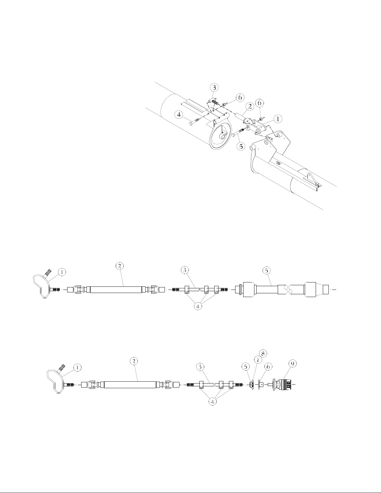
Auger Fold System
The auger folding mechanism is hydraulically operated. When in the operating position it locks into
place by “breaking over center”. The screw adjustment that determines the locking pressure is set
at the factory so the auger will break over center and lock into place. Adjustments may be required
later to ensure auger snaps into locked position. If adjustment is necessary, extend threaded end
by ONLY one turn, then operate. Repeat if necessary. DO NOT OVER EXTEND! Grease weekly
when in use.
Item Qty Part No. Description
1 1 969568 Fold Lug
2 1 967505 Linkage Female End
3 1 967497 Linkage Threaded End
4 1 333724 HHCS 1 1/4" x 7"
5 1 338236 HHCS 1 1/4" x 9"
6 2 338228 Nylock Hex Nut 1 1/4"
Drive System
PTO and (optional) Hydraulic Drive Systems
The drive system on the 850 consists of a gearbox which is mounted on the bottom end of the
auger and connected to the back drive shaft. The back drive shaft is then connected to the 1 3/8"
splined middle shaft. The middle drive shaft is then connected to either the PTO shaft (PTO drive
models) or a chain coupling and hydraulic motor (hydraulic drive models). The drive system is then
connected to the tractor by either the PTO shaft or hydraulic hoses.
PTO Drive
Item Qty Part No. Description
1 1 472407 Gear Box 50 Degree 1:6:1
2 1 608661 Back Drive shaft
3 1 607606 Front Drive shaft
Item Qty Part No. Description
4 3 403493 Bearing 1 3/8" Pillow
Block
5 1 608653 PTO Shaft
Hydraulic Drive
Item Qty Part No. Description
1 1 472407 Gear Box 50 Degree 1:6:1
2 1 608661 Back Drive shaft
3 1 607606 Front Drive shaft
4 3 403493 Bearing 1 3/8" Pillow Block
5 1 968172 Sprocket #80 12T
1 3/8" x 6 Splined Hub
Item Qty Part No. Description
6 1 968180 Sprocket #80 12T
1 1/4" Hub
7 1 433920 Chain #80-2 x 11 P
8 1 433912 Chain #80-2 Connector
9 1 472944 Hydraulic Motor

13
#608885 - PTO Clutch
Drive System
Converting to PTO or Hydraulic
To convert your cart from PTO drive to a hydraulic drive, you must first purchase a hydraulic drive
kit. The kit includes the hydraulic motor, hoses, mounting plate, and the chain coupling necessary
for the conversion.
Remove the PTO shaft from the drive shaft. Install the chain coupling onto the end of the drive
shaft. Then slide the hydraulic motor shaft into the other end of the coupling and mount the motor
on the hydraulic motor bracket that comes welded to your cart. The motor must be mounted in
such a manner that the two faces of the chain coupling are parallel. It may be necessary to shim
the motor with flat washers to achieve proper alignment. Failure to align will result in excessive
wear of the coupling. Carefully connect the hydraulic hoses provided with the kit to the motor and
torque the fittings to 30 lb./ft. maximum. DO NOT OVER TORQUE. The hydraulic hose kits
provided are equipped with dual hose connections. This requires the use of two hydraulic tractor
remotes, but the auger will turn much faster. If you do not have an extra remote, the system will
work using only one port. In this case block one of the twin ½" hoses on each hose set.
To convert from hydraulic to PTO, do the opposite of the above procedure.
Rear PTO Driveshaft
The rear telescoping shaft utilizes the same parts as the tractor PTO. It is equipped with a 1 3/8 x
6 spline clamp bolt yoke on both ends. This facilitates removal in case of maintenance.
The PTO shaft should be greased daily when in use.
Tractor PTO Driveshaft
The PTO telescoping drive shaft used on the 850 cart has been selected for the use on this
application by the Walterscheid engineers. It has a built-in friction clutch with over-running feature
to virtually eliminate damage to the drive components by excessive torque or inertial stress from
the 18" auger system.
When using your cart for the first time or when changing tractors make sure there is at least 3" of
travel left in the PTO when connected to tractor. If not, the shaft could jam causing severe damage.
The PTO shaft should be greased daily when in use. Every year the clutch should be checked,
cleaned, and repaired if necessary.
The PTO shaft supplied with your cart has a 1 3/4" x 20 spline tractor end. This is standard and fits
all new larger tractors.
Item Part No. Description
1 608893 Bolt M10 x 1.5 x 25mm
2 608901 Housing
3 608919 Friction Disc
4 608927 Separator Plate
5 608935 Pressure Plate
6 608943 Spring
7 608950 Compression Plate
8 608968 Bolt 5/16-18 x 2½ Grade 8
9 608976 Nut 5/16-18
14
Drive System
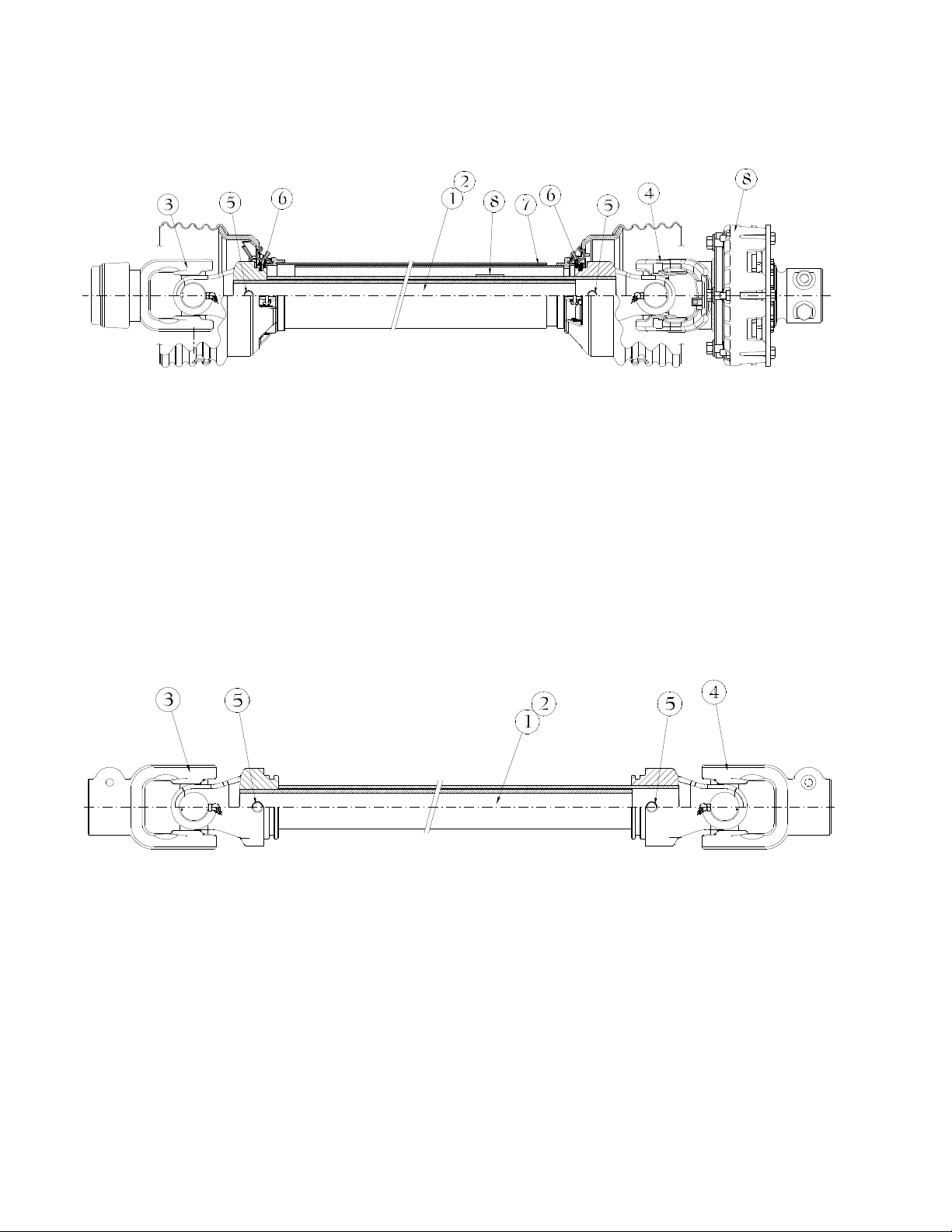
#608653
PTO Shaft - Front
Item Part No. Description
1 608984 Lemon Tube Inner
2 608992 Lemon Tube Outer
3 609008 Yoke 1 3/4-20 Spline
609016 Cross Kit
609032 Lemon Yoke
Item Part No. Description
4 609024 Yoke 1 3/8-6 Spline
609016 Cross Kit
609040 Lemon Yoke
5 609057 Roll Pin
6 609065 Bearing Kit
7 609073 Guard
8 608885 Clutch
#608661
PTO Shaft - Rear
Item Part No. Description
1 608984 Lemon Tube Inner
2 608992 Lemon Tube Outer
3 609081 Yoke 1 3/8-6 Spline
609016 Cross Kit
609032 Lemon Yoke
Item Part No. Description
4 609081 Yoke 1 3/8-6 Spline
609016 Cross Kit
609040 Lemon Yoke
5 609057 Roll Pin
15
Drive System
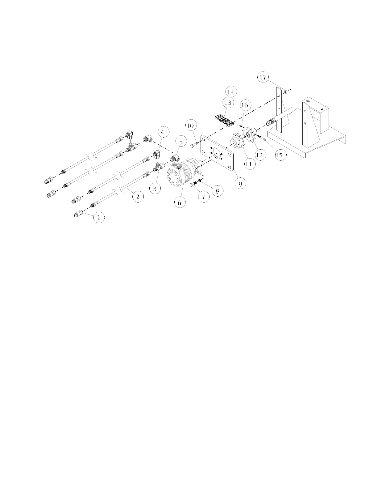
Hydraulic Drive
Minimum tractor requirements for hydraulic drive: 22 gpm @ 2500 psi.
Item Part No. Description
1 465385 Male Coupler 3/4" FOR
2 472951 Hose ½" x 84"
3/4 MOR x 1 1/16 JICF Sw
3 03556800 Tee 1 1/16 JICM (2) x
1 1/16 JICF Sw
4 00562900 Adapter 90D
1 1/16 JICF Sw x 1 1/16 JICM
5 00601500 Adapter 45D
1 1/16 JICM x 1 1/16 MOR
6 472944 Hydraulic Motor
7 01147800 HHCS ½" x 1½”
8 330142 Lock Washer ½"
Item Part No. Description
9 227942 Motor Mount
10 331926 HHCS ½" x 2"
11 968180 Sprocket #80 12 Tooth
1 1/4" Hub
12 968172 Sprocket #80 12 Tooth
1 3/8 x 6 Splined Hub
13 433920 Chain #80-2 x 11 Pitches
14 433912 Chain #80-2 Connector
15 331710 HHCS 5/16" x 2 ½"
16 331611 Nylock Nut 5/16"
17 331363 Nylock Nut ½"

16
Drive System
Gearbox
The gearbox used on all carts is a heavy duty box and gears that will rarely need repairing.
However, if repairs are required, the gear case can easily be unbolted for replacing the bearings,
seals, gears, and shafts. Often, the gearbox shaft is stuck in the spline bushing of the bottom drive
plate. (Refer to section on bottom drive plate.) In this case raise the bottom auger a few inches.
This will expose the stainless steel bolt located on top of the bottom drive plate bushing. Screw the
bolt in to push the gearbox out of the bushing. Return the bolt to its original position when finished.
The gearbox shaft is NOT fastened to the spline bushing in any way. (See the gearbox drawing for
part numbers.)
Check the oil level in the gearbox every season and check for leaks daily. DO NOT overfill the
gearbox. If oil is leaking from the gearbox, then the seals are probably worn and need replacing.
DO NOT run the gearbox if it is low on oil. Damage to gearbox could be severe.
Assembling Gearbox
When bolting the case halves back together the cleaned surfaces must be primed with Loctite
#19269 and coated with Loctite gasket eliminator #515. The bolts must be torqued evenly (38 to
45 lb./ft.). DO NOT OVER TORQUE. Replace oil in the gearbox (SAE 90).
#472407 - Gear Box
Item Part No. Description
1 472761 Output Shaft Assembly
2 472779 Input Shaft Assembly
3 472787 Plug
4 472795 Casting
5 472803 Casting -w/tapped holes
6 472811 Seal Input
Item Part No. Description
7 472829 Bearing Race Input
8 472837 Bearing Cone Input
9 472845 End Cap
10 472852 Seal Output
11 472860 Bearing Race Output
12 472878 Bearing Cone Output
17
Hopper and Components
General
The hopper on the 850 cart is constructed of sheet metal. All carts are equipped with a grain flow
control door (also referred to as a slide door) mounted on the bottom of the hopper. This door and
the hydraulics required to operate it are considered part of the hopper assembly. In addition, the
auger transport saddle and the lighting kit are considered part of the hopper.
Do not store your cart with grain or other material left in the bottom. The hopper should be cleaned
before storing and the drain door located at the bottom of the auger tube should be opened to
permit water drainage. Repair and paint any damaged areas on the hopper.
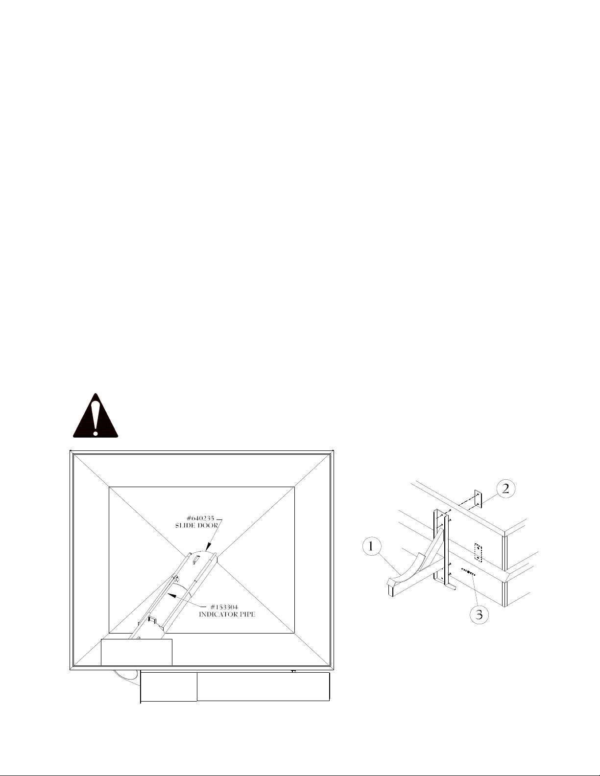
Grain Door (Slide Door)
The grain flow control door is hydraulically operated from the tractor. It is used to close off or control
the grain flow to the auger. It is recommended that this door be completely closed when pulling the
cart in the field. This will prevent grain from packing into the bottom of the auger. This could cause
possible damage to the drive system on the PTO models or the hydraulic motor to stall on the
hydraulic driven models.
An indicator is located on the front of the cart hopper to show whether the door is opened or closed.
The door can also be used to regulate the amount of grain going to the auger. This may be useful
when loading grain drills or other containers where only a limited amount of grain is needed. In such
cases, DO NOT simply run the auger slower as this could cause damage to the drive system.
Instead, use the grain-flow control door.
Before using your cart for the first time, make sure this door is opening and closing properly. If it is
not, you will not be able to unload the cart.
Auger Saddle
The auger transport saddle is located on the left back side of the cart. Always fold the auger back
into the saddle when transporting the cart. Make sure the auger rests firmly in the saddle.
CAUTION:
Keep everyone clear of the cart while folding or unfolding the auger.
Item Part No. Description
1 969899 Auger Saddle
2 229278 Back Up Plate
3 229260 Back Up Plate -Short
18
Frame and Axle
General
The frame and axle of the cart are built of different materials depending on the model of the cart. In
most cases, however, the frames and axles are designed to withstand the most demanding farm
use with a considerable margin of safety.
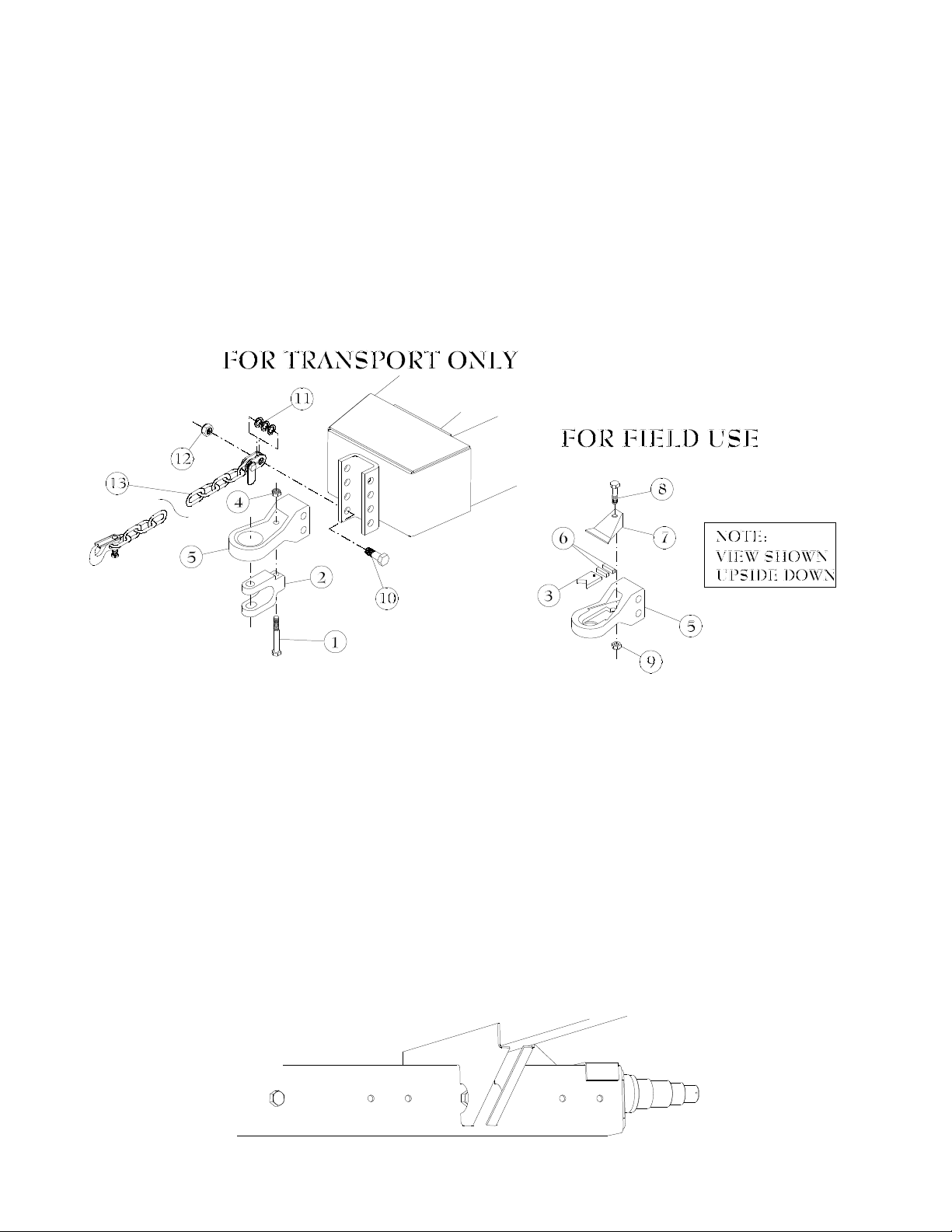
Hitch Assembly
Your tractor must have a clevis type draw bar.
The hitch on the 850 cart is a ring type hitch similar to those used on implements in Europe. It is
adjustable up and down to allow for different draw bar heights. It also is adjustable for 1½" or 2"
hitch pin diameters. It allows for angular motions of 40 degrees, thus eliminating the need for a
slotted hitch pin hole or a rotating hitch.
The clevis attachment furnished is for transporting empty cart only. DO NOT use clevis
for field use.
#873547 - Hitch Assembly
Item Qty Part No. Description
1 1 333294 HHCS 3/4" x 6" Gr8
2 1 607481 Hitch Clevis
3 1 607499 Hitch V-Block
4 1 00497800 Hex Nylock Nut 3/4" Gr8
5 1 607465 Hitch Spade
6 2 607507 Clevis Cushion
7 1 607515 Top Plate
Item Qty Part No. Description
8 1 02307700 HHCS 3/4" x 3" Gr5
9 1 330316 Hex Nylock Nut 3/4" Gr5
10 1 334987 HHCS 1" x 3"
11 3 335166 Machine Bushing
1" x 10 ga
12 1 330597 Hex Nylock Nut 1"
13 1 433946 Safety Chain 21,000#
Axle
The carts are all equipped with an adjustable axle. This enables the operator to set the tire track to
match the row spacing of his crops. The factory settings are at 120", 144" and 152". New holes
may be drilled in the axle for intermediate settings if the owner desires.
Axle Adjustment
The axle is shipped in the 120" setting. To extend the axle, block up one side of the cart off the
ground, being very careful that the blocks used are sturdy and safely placed. Loosen the bolts
running through the axle and remove them. Pull the axle to the next hole setting and replace bolt.
Make sure the bolts are torqued to specification. (See torque chart). Repeat procedure for the
other side of the cart.
Table of contents
Other CrustBuster Outdoor Cart manuals

Popular Outdoor Cart manuals by other brands


Carts Vermont
Carts Vermont 20 manual

Westward
Westward 2CZY4 Operating instructions and parts manual

Numatic
Numatic EcoMatic EM-5 Assembly

Bosch
Bosch XL-Cart Operating/safety instructions

Tennsco
Tennsco Modular Cart Top Component Assembly Assembly Instructions/Parts Manual

Clam
Clam POLAR TRAILER HD MAX manual


