CrustBuster Seed Box Tote User manual

P.O. Box 526 - Spearville, Kansas 67876 - (620) 227-7106
crustbuster.com
Seed Box Tote
Back Load Unit
OWNER'S MANUAL
#04175600 UPDATED 04/2021 (2013)


Table of Contents
Warranty Information . . . . . . . . . . . . . . . . . 1
Operator Qualifications. . . . . . . . . . . . . . . . 2
Safety and Warnings . . . . . . . . . . . . . . . . 3-6
FuelValve ......................... 7
Loading Seed in Tote Boxes . . . . . . . . . . 8-9
Wiring Diagram . . . . . . . . . . . . . . . . . . 10-11
Belt Assembly . . . . . . . . . . . . . . . . . . . . . 12
Operation, Maintenance, Belt Training . 13-14
Dimensions . . . . . . . . . . . . . . . . . . . . . . . 15
Repair Parts:
Stand - Gas with Telescoping Tube and
Remote (Prior 2021) . . . 16-17
Stand - Gas with Standard Tube and
Remote (Prior 2021) . . . 18-19
Stand - Electric with Standard Tube
(Prior 2021) . . . . . . . . . . . . . . . . . . . 20-21
Stand - Gas with Telescoping Tube and
Remote . . . . . . . . . . . . . 22-23
Stand - Gas Hardwire w/ Actuator . . 24-25
Stand - Gas Remote w/ Actuator . . . 26-27
Stand - Electric w/ Actuator . . . . . . . 28-29
Standard Tube -Gas . . . . . . . . . . . . . 30-31
Standard Tube -Electric . . . . . . . . . . 32-33
Standard Tube -Gas w/ Actuator . . . 34-35
Standard Tube -Electric w/ Actuator . 36-37
Telescoping Tube Assembly
Gas w/ Actuator . . . . . . . 38-39
Gas................ 40-41
Support Frame. . . . . . . . . . . 41
Top and LowerTubes . . . . . . 42
Wind Guard . . . . . . . . . . . . 43
Upper Roller Bracket . . . . . . 43
S-wrap Roller . . . . . . . . . . . . 43
Electric Winch . . . . . . . . . . . 44
Shaft & Sprocket Assy . . . . . 44
Handle Assy. . . . . . . . . . . . . 44
SeedSpouts...................... 45
Flexible Tube Spouts . . . . . . . . . . . . . . . 46
Engine Assemblies . . . . . . . . . . . . . . . . . 47
DryTalc ...................... 48
Trailer ................... 54-56
Options:
Remote Enclosure Assy . . . . . . . . . . 48-51
Remote Control . . . . . . . . . . . . . . . . . . . 52
Identification
Your Seed Tender is identified by a Serial Number and Model Number. Record these numbers in the
spaces provided in this manual and refer to them when ordering parts or requesting service.
Serial Number Model Number
Warranty
CrustBuster/Speed King, Inc. of Spearville, Kansas, warrants consumer products, so far as
the same is of our own manufacture, against defects in material and workmanship under
normal and reasonable use for a period of one (1) year after date of delivery to the original
purchaser. Our obligation under this warranty is limited, however, to furnishing a replacement
part for a defective part, or at our option to repair the defective parts without charge, either
method F.O.B. our works, provided the consumer gives CrustBuster/Speed King,Inc. written
notice within ten (10) days after said part appears to be defective and affords
CrustBuster/Speed King,Inc. an opportunity to inspect. Unless otherwise expressly agreed
to by CrustBuster/Speed King,Inc., the consumer shall bear the expense of installation.
CrustBuster/Speed King, Inc. will not be liable for consequential damages where the loss is
commercial, including but not limited to loss of profit, delays or expenses.
This warranty sets forth the extent of our liability. The foregoing is in lieu of all other
warranties, expressed or implied, including any warranties that extend beyond the description
of the product.
1

Operator Qualifications
Operation of this Seed Tote shall be limited to competent and experienced persons. In addition,
anyone who will operate or work around this equipment must use good common sense. In order to
be qualified, he or she must also know and meet all other requirements, such as:
1. Some regulations specify that no one under the age of 16 may operate power
machinery. It is your responsibility to know what these regulations are in your
area or situation.
2. Current OSHA regulations state in part: "At the time of initial assignment and at
least annually thereafter the employer shall instruct EVERY employee in the
safe operation of servicing of all equipment with which the employer is, or will
be involved."
3. Unqualified persons are to STAY OUT of the work area.
4. A person who has not read and understood all operating and safety instructions
is not qualified to operate the machinery.
FAILURE TO READ THIS SEED TENDER MANUAL AND ITS
SAFETY INSTRUCTIONS IS A MISUSE OF THE EQUIPMENT.
Sign Off Sheet
As a requirement of OSHA, it is necessary for the employer to train the employee in the safe operation
and safety procedures with this Seed Tender. We include this sign off sheet for your convenience and
personal record keeping.
DATE EMPLOYER EMPLOYER'S SIGNATURE
2

BE ALERT!
Your Safety is involved.
General Safety Statement
WATCH FOR THIS SYMBOL. IT POINTS OUT IMPORTANT
SAFETY PRECAUTIONS. IT MEANS "ATTENTION ))) BECOME
ALERT!"
YOUR SAFETY IS INVOLVED.
It is your responsibility as an owner, operator, or supervisor to know and instruct everyone
using this Seed Tender at the time of initial assignment and at least annually thereafter, of the
proper operation, precautions, and work hazards which exist in the operation of this Seed
Tender in accordance with OSHA Regulations.
Safety Is No Accident
The following safety instructions, combined with common sense, will save your equipment
from needless damage and the operator from unnecessary exposure to personal hazard. Pay
special attention to the caution notes in the text. Review this manual at least once each year
with new and/or experienced operators.
1. Read and understand the operator's manual before operating this Seed
Tender. Failure to do so is considered a misuse of the equipment.
2. Make sure Seed Tender is secure before operating.
3. Always keep children away from Seed Tender when operating.
4. Make sure everyone that is not directly involved with the operation is out of
the work area before beginning the operation.
5. Make sure all safety devices, shields, and guards are in place and are
functional before beginning the operation.
6. Shut off power to adjust, service, or clean.
7. Keep hands, feet, and clothing away from moving parts. It is a good idea to
remove all jewelry before starting the operation.
8. Visually inspect the Seed Tender periodically during operation for signs of
excessive vibration, loose fasteners, and unusual noises.
9. Before transportation unit, make sure tube assembly is locked into place and
safety strap is on and secure.
10. Keep box tote on level surface.
DANGER: Indicates an imminently hazardous situation which, if not avoided, will result in
death or serious injury.
WARNING: Indicates a hazardous situation which, if not avoided, could result in death or
serious injury.
CAUTION: Indicates a potentially hazardous situation which, if not avoided, may result in
minor or moderate injury.
NOTICE: Used to address practices not related to physical injury.
3

Safety Decals
REMEMBER: If Safety signs have been damaged, removed, become illegible or parts replaced without
decals, new decals must be applied. New decals are available from your authorized
distributor or factory. Individual decals shown below.
#05326400 #05303300
#05312400
#05328000
#05316500
#05310800
4

Danger
BE ALERT! YOUR PERSONAL SAFETY IS INVOLVED.
ALWAYS PARK TENDER ON LEVEL SURFACE TO UNLOAD.
Before releasing safety strap that secures tube assembly, make
sure tender is sitting on a level surface.
If parked on an unlevel surface, and the tube assembly is not
restrained, it could swing rapidly and out of control to one side or
the other.
The rope attached to the tube is to assist in guiding the tube. If
tube is swinging out of control, the rope may not control the tube.
If parked on an unlevel surface with the spout side down, (See
illustration A)the tube could rapidly swing out.
5
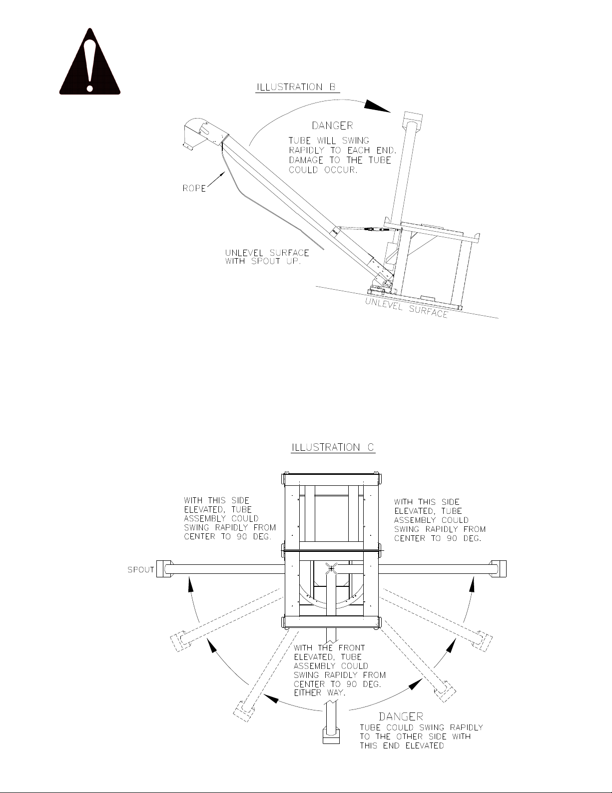
If parked on an unlevel surface with the spout
side up, (See illustration B)the tube will rapidly
swing to one end or the other depending on
which side the gravity pulls it. This could be
very hazardous for anyone standing in its path.
Be very cautious of situation.
If parked on an unlevel surface with the spout
side up, (See illustration C)the tube could
rapidly swing from one end to the other.
This could be very hazardous for anyone
standing in its path. Be very cautious of this
situation. This could also cause damage to the
tube assembly.
Danger
6

FUEL VALVE
When engine is not in use, leave the fuel
valve lever in the OFF position to prevent
- carburetor flooding
- fuel in the oil crank case because of
transporting vibrations
- the possibility of fuel leakage.
See engine owner’s manual to help you avoid
other damage to your engine.
CAUTION
NOTE: CrustBuster recommends fuel
valve be shut off and the motor
run completely out of fuel before
transporting.
7

NOTE:
For proper seal to hopper,
container should be lowered
straight down as shown. Make
sure there is no debris on hopper
top. Make sure rubber skirtboard
deflector is not bent under and
preventing a good seal.
CAUTION
FAILURE TO EXTEND FORKS UNDER
OAK INSERTS WILL CAUSE DAMAGE
TO SLIDE DOOR ON THE UNDER
SIDE OF CONTAINER. THIS IS A
DANGEROUS SITUATION ALSO.
Assembly
CAUTION
ALWAYS LIFT THE CONTAINER FROM THE BOTTOM. NEVER USE STRAPS OR
LIFT BY TYING ANYTHING TO THE SIDES OF THE CONTAINER. REQUIRES
MINIMUM 3000 LB. FORKLIFT TO PICK UP FULL CONTAINER. OAK INSERTS,
LOCATED IN THE BASE OF THE CONTAINER, REDUCE LIPPAGE ON FORKLIFT
FORKS AND PROVIDE STRUCTURAL SUPPORT.
8

TO LOAD SEED BOXES, THE
TOTE SHOULD BE ON LEVEL
GROUND OR SURFACE AS
SHOWN.
IF IT IS NOT POSSIBLE TO
LOAD ON A LEVEL SURFACE,
LOAD THE DOWN HILL
CONTAINER FIRST, AS
SHOWN.
THIS IS THE RIGHT WAY!
IF YOU LOAD THE UP HILL
BOX FIRST, IT WILL BE VERY
DIFFICULT TO GET THE
SECOND BOX LOADED.
THIS IS THE WRONG WAY!
Seed Box Loading
9
Wiring Diagram
For Electric Units
10
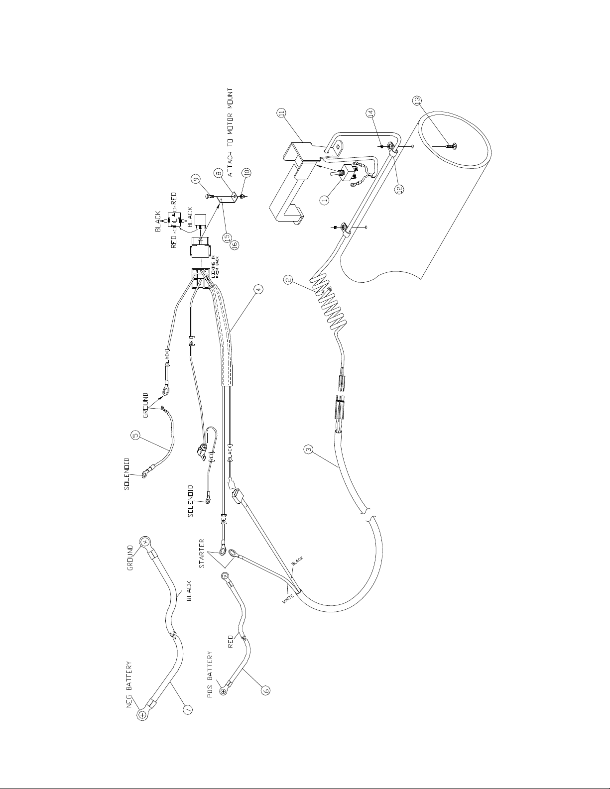
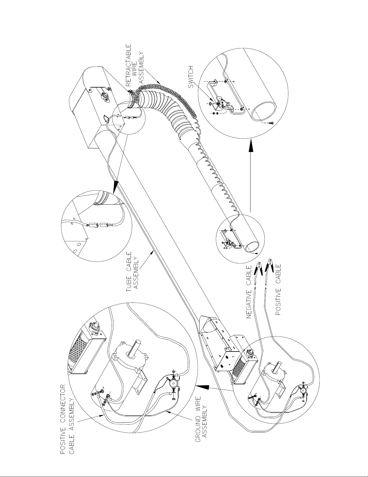
Wiring Diagram
For Gas Units (without remote)
11
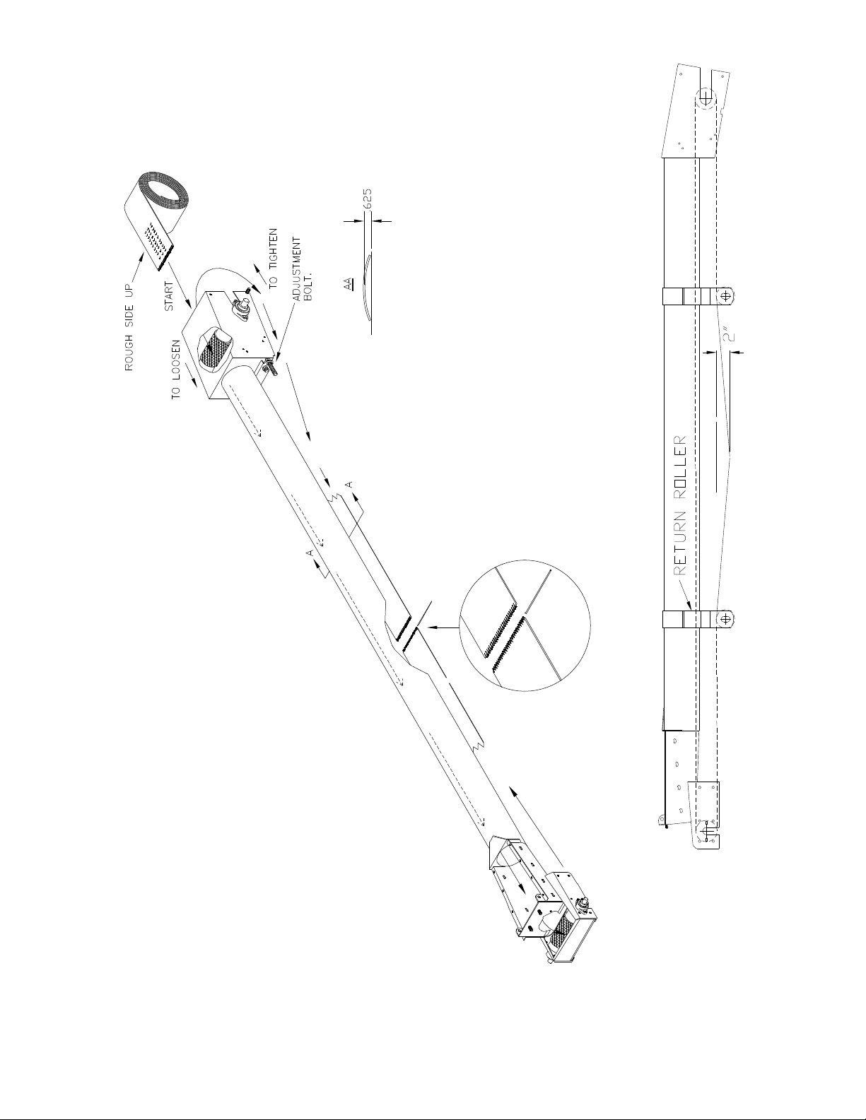
BELT TIGHTENING
INSTRUCTIONS
Belt should be tightened before
you train the belt. Tightening the
belt is done on the head roller by
tightening the take up bars
evenly. Belt is tight when
applying 25 lbs. of force,
centered between the return
rollers, there is no more than 2
inches of deflection.
BELT ASSEMBLY INSTRUCTIONS
At the start point, see view of head and tail assembly.
Drop belt over the top of head roller and gravity feed belt
down the tender tube to the bottom. Guide the belt over
the top of the tail roller. Make sure rough side is UP and
the smooth side is DOWN against the inside of wall of the
tube.
Route both ends around head and tail rollers and over all
return idlers mounted under the tube. Slide belt forward
or back through tube so the ends of the belt meet at a
convenient location between return idlers to facilitate
joining.
Align and interlace belt and clipper lacings. Slip splice pin
(Plastic covered cable) through clipper lacings to secure.
Belt Assembly
12

Pre-Operation Check List
1. Check all bearings for proper lubrication.
2. Check the tube for foreign material.
3. Check belt for proper tension.
4. Start unit and check tender belt alignment while unit is empty.
BELT CARE ………
It is suggested that the unit be run every two to three days or more often if possible. This tends to
keep the belt alive and stops any forming of the belt to the curvature of the tube while the unit is
not in use.
NOTE: Belt may deteriorate if not in use and exposed to weather conditions for any prolonged
period of time.
Operation Sequence
1. Check drive chain for proper tension.
2. Make sure tender belt is properly tensioned.
3. Allow unit to run empty for a few minutes to flex tender belt.
4. Check tender belt for proper alignment.
5. Before shutting power off, be certain head and tail unit is empty.
STORAGE ………
Temporary Storage
1. Relieve tension on tender belt.
2. Store all belt equipment in a dry place. If equipment cannot be stored out of the weather,
cover engine and mechanical parts with waterproof material.
Prolonged Storage
1. Remove all belts and store in a cool, dark, dry place.
2. Wash tender belt thoroughly.
3. Wash tender tube both inside and out.
4. Lubricate all bearings.
5. Store in a dry shelter.
Maintenance
Preventive maintenance is the key to the long life of any mechanical device.
Careful and systematic inspection of the Seed Tender will result in maximum, trouble-free service.
BELT REPLACEMENT ………
To replace the belt, cut it into and hand rotate the head roller until belt has been removed. Install
appropriate belt as outlined in assembly instructions.
HEAD ASSEMBLY TAKE-UP ………
After extended use, the tender belt may stretch to the point that there is not sufficient take-up in
the head assembly to tighten it. Obtain additional take-up by cutting a 6" to 8" section from the
belt. A new splice lacing may be ordered from your CrustBuster/Speed King distributor or from the
factory.
PERIODIC CLEAN-OUT ………
Due to the characteristics of certain materials, residue sometimes collects between the tender belt
and the tube. Check the unit periodically for any material build up in this area. If residue appears
excessive, remove the tender belt and thoroughly wash the belt and tube. Allow belt and tube to
dry before reinstalling the belt.
When the tender is not being used, secure belt to the tube to prevent belt from flopping in the wind,
possibly breaking return idlers or ripping belt.
LUBRICATION ………
All bearings which are fitted with grease zerks should be lubricated at the conclusion of each
operating day. Before greasing the bearings, make certain the zerks are free of dirt, otherwise this
will be passed into the bearing race. If the unit will be out of service for a period of time, purge the
bearings.
BELT TRAINING PROCEDURE ………
A tender belt correctly installed and trained will run straight and true. The belt must run centered
on all terminal rollers, take-up rollers, and return idlers throughout the entire belt length.
Incorrect installation and training can result in severe edge damage, material spillage, material
leakage through the skirt rubber at the loading point, and excessive power demands. Material
spillage is the usual reason for belt carcass ruptures and pulley cover gouging and stripping, while
leakage at the skirt rubber results in excessive conveyor cover wear under the skirts.
13

Maintenance - (cont’d)
ALIGNMENT ………
All rotating parts -head roller, tail roller, and return idlers- must be at a 90 degree angle to the
direction of belt travel, must be level, and the midpoint of each centered on a line when properly
aligned.
Alignment is checked by running a tight wire from the center of head roller to center of the tail roller.
Level all rotating parts. If a part is not level, the belt will run to the lower side.
BELT SPLICING ………
A belt must not run out at the splice area. Runout will occur if the belt is not cut square or splice
is not installed square.
Operation
1. Prior to the start-up, check to see that belt is free from any objects that would bind or tear.
2. On starting for the first time, with no load on belt, apply power for a few seconds only to see
that the tender belt is well centered in the tube and on the return.
3. It should be noted at this time that too much tension on the tender belt will make adjustment
or training much more difficult, shorten the life of the belt, and waste power. The belt should
be tensioned tight enough so the drive roller does not slip. The belt is tight when applying 25
pounds of force, centered between the return rollers, there is no more than 2 inches of
deflection.
BELT TRAINING ………
It is essential that the tender belt be properly trained at all times. For this reason, all rotating parts
should always be at right angles to the tender belt.
Slight adjustment of roller shafts may be required to keep belts centered on them i.e., if the belt
runs to one side of the roller - apply more tension to this side of the belt by advancing the roller
shaft on this side. This can be done on the head section as long as adjustment bolt does not vary
more than 1/4". If it does, and belt will still not center on both rollers, the tail section is probably out
of square.
To square tail section roller, even out the head roller until adjustment bolts are equal. On tail
section, loosen bearing bolts on opposite side the belt is off. CAUTION: LOOSEN BEARING
BOLTS JUST ENOUGH SO IT TAKES A BLOCK OF WOOD AND A SMALL HAMMER TO MOVE
THE BEARING. To adjust tail section, 1/32" in most cases, will move the belt. Tail roller bearings
only have about a 1/16" to 3/32" movement total. Tighten the bearing, and go to the head section
and retrain the belt.
If the belt tends to veer to one side of the return strand, the belt can be centered by "knocking"
ahead (in the direction of belt travel) the end of the return idler to which the belt runs. A belt
correctly installed will usually train well both empty and loaded, except as noted:
1. One or more rotating parts not in alignment.
2. Belt tensions in some part of system (usually at tail section) are below minimum
recommended.
3. Belt not loaded centrally.
When a belt is initially started, it should be jogged around the system to determine if a major runout
occurs which could damage belt and belt edges. If runout occurs at some point of the system, the
reason is usually a return idler or roller out of alignment before the runout. Alignment should be
rechecked before restarting.
After the belt can be safely run without damage, final training should begin with the head roller.
The belt must enter the head roller in the center without movement from side to side. If the belt
is not centered on the tail pulley, the return strand of belt should be observed for any section which
is not centered on the return idlers. If the belt is not centered at some point, move return idlers
starting before this point to correct centering of belt. Movement of idler bracket should be gradual
and only 1/16" to 1/8" remembering that the belt will move in the direction that it first contacts the
idler. The same corrective action should be taken at the tail roller.
After the belt is trained empty, the belt should be trained with a load. The take-up adjustments are
made to prevent belt slip and keep tensions at all points above minimums recommended when belt
is operating with a load.
If slip occurs under load, additional belt tension should be adjusting the take-up only enough to
prevent slip from occurring under load, and when started with a load.
14

Seed Box Tote
Dimensions
15

Seed Box Tote
Stand Assembly -Telescoping Tube
Gas Drive (Prior 2021)
16

Seed Box Tote
Stand Assembly -Telescoping Tube
Gas Drive (Prior 2021)
#63164800
Item Qty Part No. Description
1 1 975326 Tote Stand
2 1 879072 Telescoping Conveyor
3 1 878793 Spout Assembly
4 2 241133 Spout Gate
5 1 123448 Pivot Lock Collar
6 1 04255600 Sheave 1B 8 x 1 w/keyway
7 1 975464 Belt Guard
8 8 330894 Flat Washer 3/8"
9 21 330837 Nylock 3/8"
10 1 276337 Pivot Plate Center
11 2 276329 Pivot Plate Ends
12 12 01047000 Carriage Bolt 5/16" x 1"
13 2 242529 Insulator Bracket
14 2 03651700 Insulator
15 2 01034800 U-bolt 3/8" x 1 1/4" x 2 1/4"
16 1 63046700 Engine Assembly
17 2 975425 Load Bar
18 1 01429000 Battery Box
19 1 82099300 Conveyor Hopper
20 1 474304 V-Belt B-46
21 3 434456 Chain #4 x 17 links w/pin
22 2 03818200 Plug 1 1/4" Square
23 2 608596 Metal Loom Clamp 1/4"
24 1 607416 Manual Holder
25 1 04175600 Owners Manual
Item Qty Part No. Description
26 2 605659 Grommet
27 1 03895000 Remote Fob Box
28 1 00694000 Serial Plate
29 2 600577 Serial Plate Drive Screws
30 1 17375700 Key 1/4" x 1"
31 33' 01467000 Nylon Rope
32 1 03439700 Decal Patent #
33 1 05303300 Decal Cautions
34 2 05310800 Decal Debris Center Flow
35 1 05312400 Decal Shield Caution
36 1 05326400 Decal Tip-Over Warning
37 1/8 00843300 Silicone Caulk
38 1 976498 Belt Guard Rear
39 26 01057900 HHCS 1/4" x 3/4"
40 15 02016400 Flat Washer 1/4"
41 26 330522 Nylock 1/4"
42 4 01144500 HHCS 5/16" x 3/4"
43 4 335448 HHCS 5/16" x 1½”
44 10 330852 Flat Washer 5/16"
45 22 331611 Nylock 5/16"
46 10 330548 Carriage Bolt 3/8" x 3/4"
47 2 334847 Wing Nut 3/8"
48 8 01017300 HHCS 3/8" x 1"
49 1 330886 HHCS 3/8" x 3"
50 2 976902 Spout Assembly Mount
17

Seed Box Tote
Stand Assembly -Standard Tube
Gas Drive (Prior 2021)
18
Table of contents
Other CrustBuster Outdoor Cart manuals

Popular Outdoor Cart manuals by other brands

Knurr
Knurr Dacomobile Extension shelf Assembly instructions

Rockler
Rockler Material Mate instructions

JohnDow Industries
JohnDow Industries GAS & GO GG-25PFC-D Operator's manual

fetra
fetra 3191 Operation manual

MedViron
MedViron Height Adjustable Medical Carts Operation & maintenance manual

Sauder
Sauder Studio RTA 408343 Instruction booklet


